
9: Chapter 9. Create a site
- Page ID
- 13185

 Session Objectives
Upon completing this session, students will be able to:
(CO 1) Understand the site plan and information
(CO 2) Set the project location and understand building base point
(CO 3) Import google maps and define true north & project north
(CO 4) Find GIS information
(CO 5) Add & Edit Site – Topo surface, roads, side works, property line, building pod, surrounding buildings, and trees
 Session Highlights
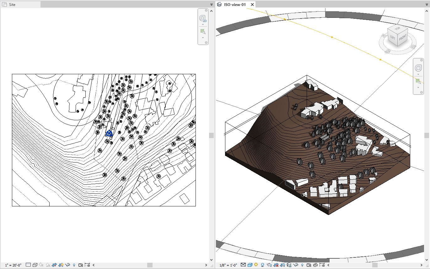
At the end of the session, students can create the graphics below.
 Lecture Contents
(CO 1) Understand the site plan and information

A YouTube element has been excluded from this version of the text. You can view it online here: https://iastate.pressbooks.pub/visualgraphiccomm/?p=90
The site plan is an architectural plan of proposed improvements to a given lot. A site plan usually shows a building footprint, travel ways, parking, and landscaping and garden elements (Department of Building and Development Land Development, 2009).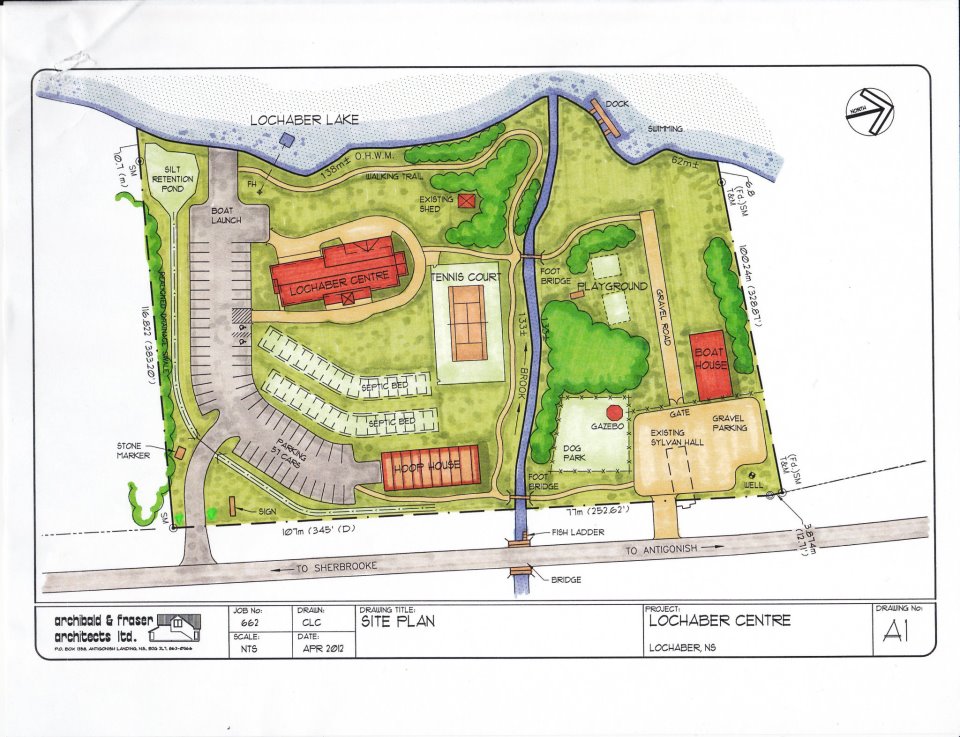
image credit: Archibald & Fraser Architects Ltd. – Wikimedia Commons – File: Lochaber Centre Site Plan.jpg
A site plan is a “set of construction drawings that a building or contractor uses to make improvements to the property. Counties can use the site plan to verify that development codes are being met and as a historical resource. Site plans are often prepared by a design consultant who must be either a licensed engineer, architect, landscape architect, or land surveyor” (Chesterfield County, 2009).
A site plan is a top view of a property that is drawn to scale. A site plan can show
- Property lines
- Outline of existing and proposed building and structures
- Parking lots, indicating parking spaces
- Driveways
- Surrounding streets
- Landscaping areas
- Terrains
(CO 2) Set the project location and understand building base point

A YouTube element has been excluded from this version of the text. You can view it online here: https://iastate.pressbooks.pub/visualgraphiccomm/?p=90
Draw the building footprint for the site plan
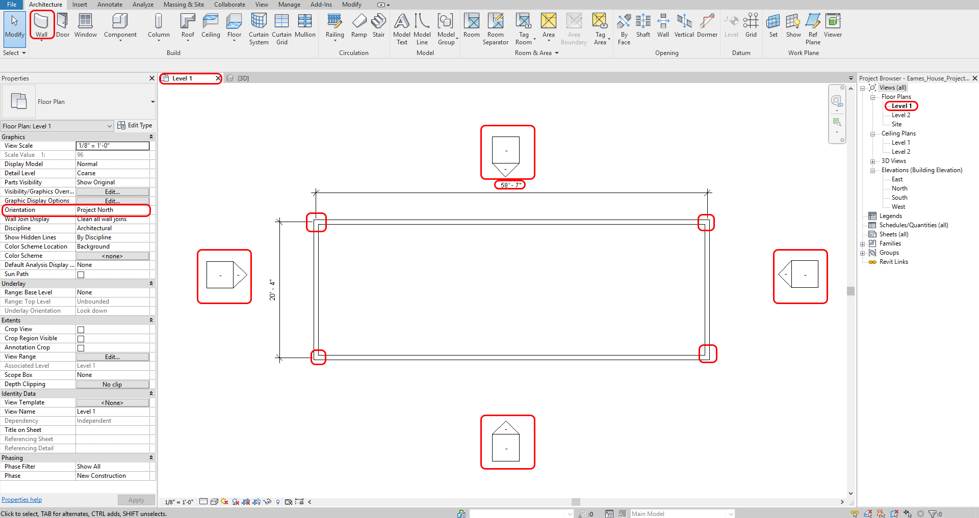
- [STEP 1] Acknowledge the overall size of the building.
- The size of the house part of the Eames House project is 58’-7” x 20’-4.”
- [STEP 2] Select [WALL] from [ARCHITECTURE] tab, under [Build] panel
Or, Type [WA] on your keyboard- Draw only overall exterior walls on level 1
- Make sure your walls are [Project North] on the [Properties] palette.
- Confirm the wall is – Basic Wall/Generic-8”, Unconnected Height 20’ 0.”
- [STEP 3] Draw the building footprint
- Click a drawing area
- Move the mouse to the right-side
- Enter 58’7” on your keyboard > press [ENTER] key
- Move your mouse to the down-side
- Enter 20’4” on your keyboard > press [ENTER] key
- Move your mouse to the left-side
- Click the third point and forth to create the building
- [STEP 4] Move the elevation symbols closer to the close the building
- Select one elevation symbol
- Type [MV]
- And click one point and move the mouse and click the target point to complete the command.
- Repeat this process to other elevation symbols
Set the project location
This setting is for sun orientation and weather information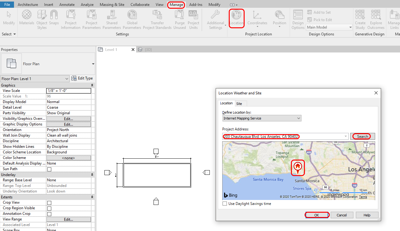
- [STEP 1] Select [LOCATION] from [MANAGE] tab, under [PROJECT LOCATION]
- [STEP 2] Enter the project address (Eames House address is 203 N. Chautauqua Blvd. Pacific Palisades, CA) and Select [SEARCH]
- [STEP 3] Select a Weather Station near the project location
- [STEP 4] Click [OK[ to complete the command
(CO 3) Import google maps and define true north & project north

A YouTube element has been excluded from this version of the text. You can view it online here: https://iastate.pressbooks.pub/visualgraphiccomm/?p=90
Save site information from Google Map
- [STEP 1] Open your web browser and go to [GOOGLE MAP] – https://www.google.com/maps
- [STEP 2] Search the address [for Eames House project, 203 N. Chautauqua Blvd. Pacific Palisades, California]
- [STEP 3] Use [Snipping tool] (search Snipping tool from your program list) – Screenshot – must include the building, and the property line, and the scale on the bottom left corner. For your drawing accuracy, I recommend saving both the map image and the satellite map image.
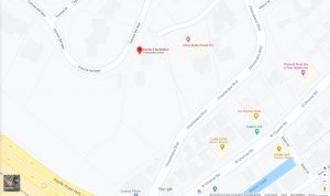
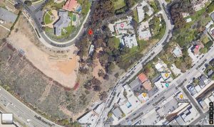
image credit: search result from Google map
- [STEP 4] Save the snipped image file in JPG file format in your project folder
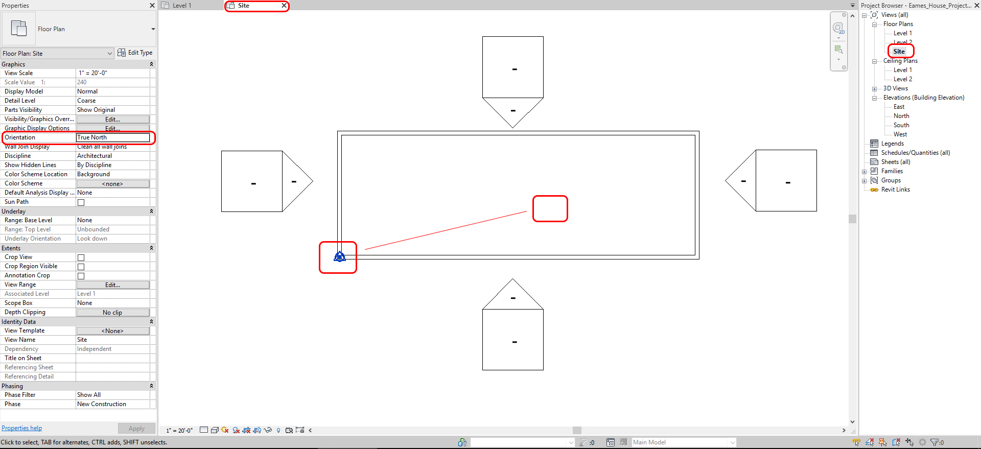
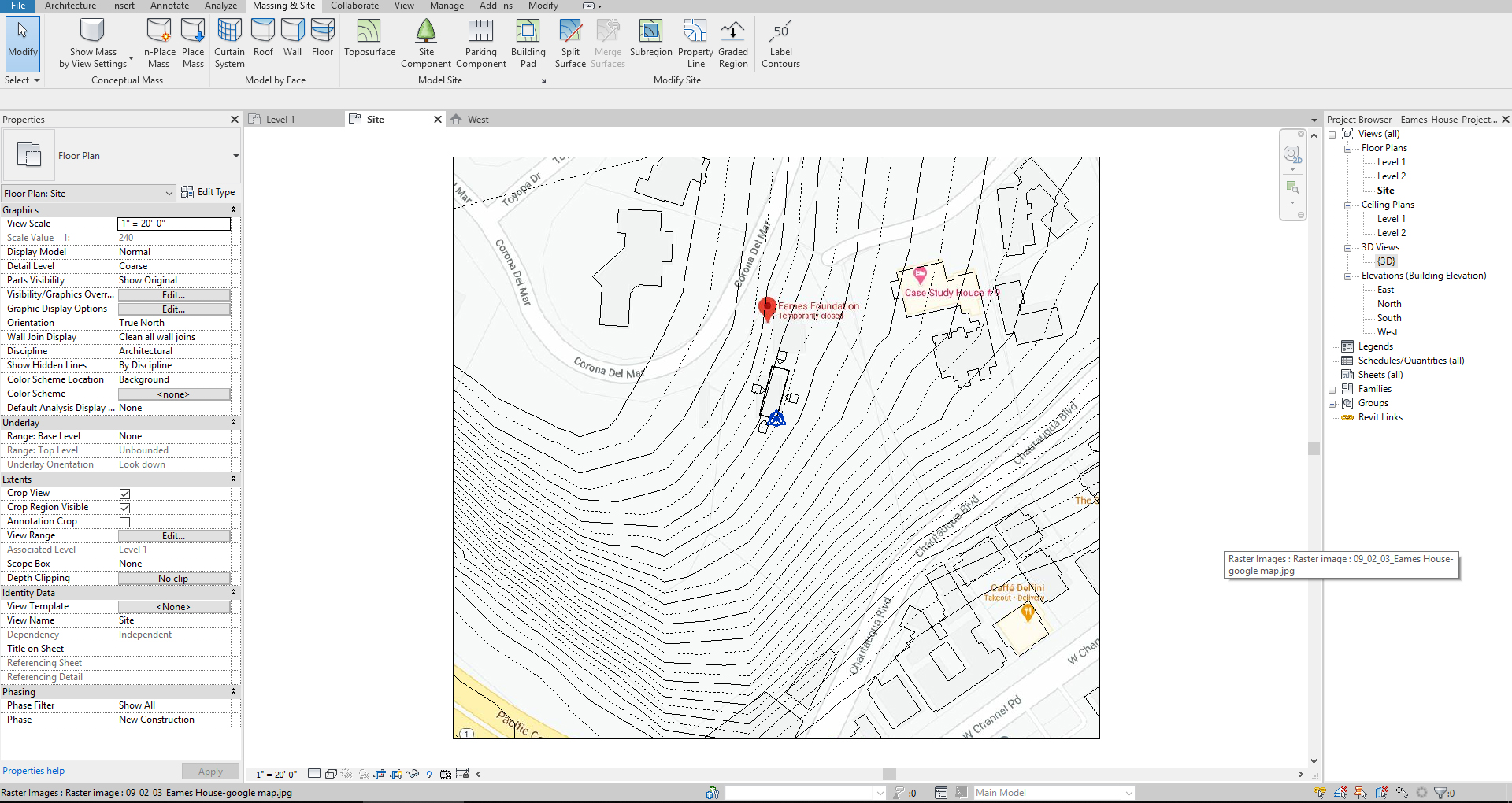
Insert site information from google map
- [STEP 1] Open [SITE] plan by double-clicking from the [PROJECT BROWSER]
- [STEP 2] Move the project origin to the building bottom left corner
- [STEP 3] Change the orientation to [TRUE NORTH]
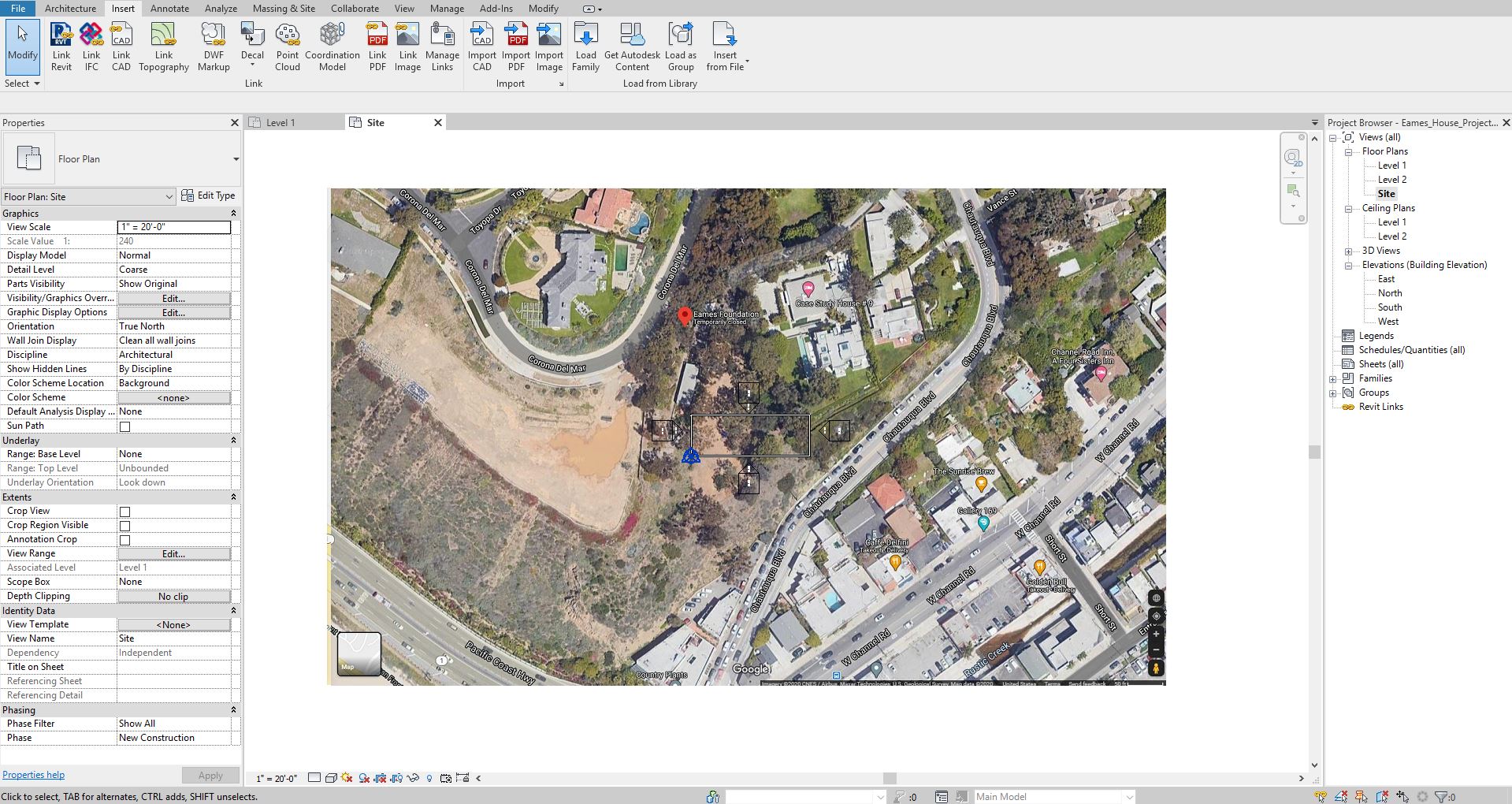
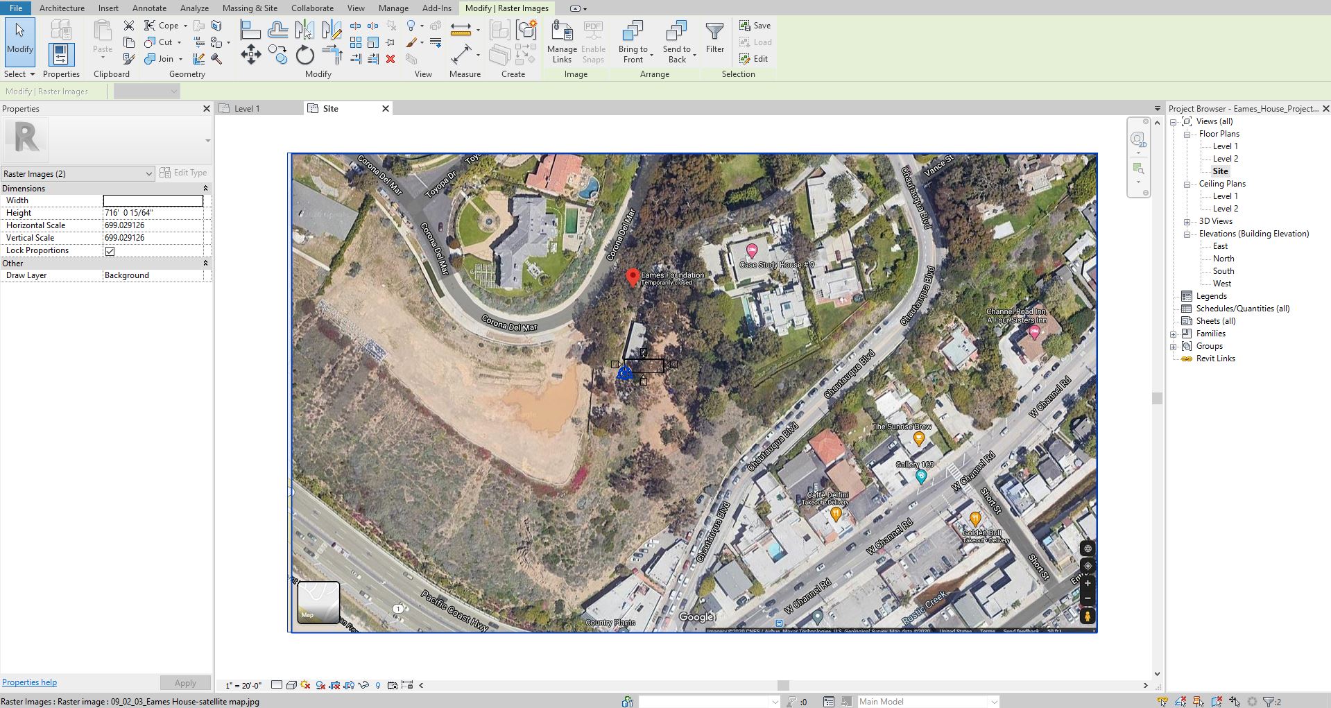
- [STEP 4] Select [IMPORT IMAGE], from [INSERT] tab
- [STEP 5] Open the project folder and select the google map and click [OPEN]
- [STEP 6] Click on the center of the drawing area
- [STEP 7] Repeat this process for the satellite map
Adjust the scale of the imported google map
- [STEP 1] Select the two imported maps by crossing selection
- [STEP 2] Click [SCALE] from [MODIFY/RASTER IMAGE] tab, under [MODIFY] panel
or, Type [RE] for adjusting the scale - [STEP 3] Zoom-in to find the graphic scale on the bottom right side of the map
- [STEP 4] Click 0ft – click 50 ft – type 50’ – Enter
- [STEP 5] Move the imported raster maps to be centered
Adjust the orientation of the imported google maps according to the building footprint
- [STEP 1] Select the imported google maps
- [STEP 2] Select [ROTATE] from [MODIFY] tab, under [MODIFY] panel
Or, Type [RO] on your keyboard - [STEP 3] Select [PLACE]
- [STEP 4] Click the base point to rotate, click an appropriate point to rotate.
Remember how many degrees you rotated (for Eames House, 75.56 clockwise)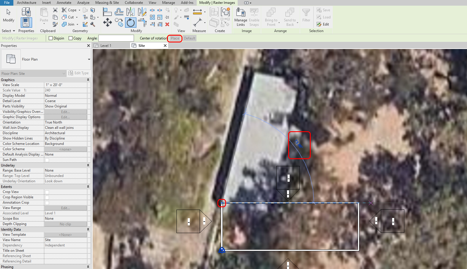
- [STEP 5] Relocate the imported google maps, if needed
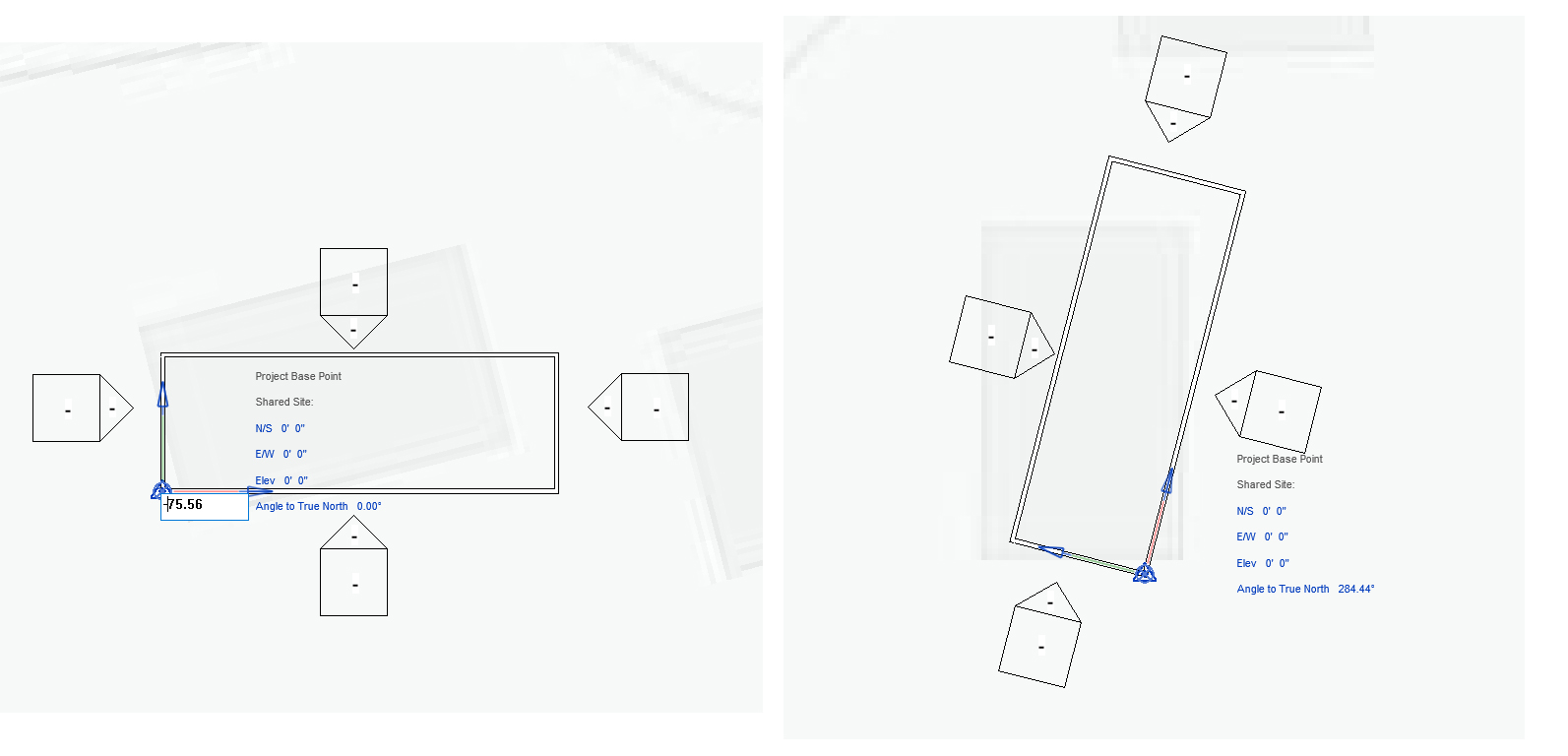
- [STEP 6] Select only the satellite map > click [SEND TO BACK] from [MODIFY/RASTER IMAGE] under [ARRANGE] panel
- [STEP 7] Select the project base origin
- [STEP 8] Click [ANGLE TO TRUE NORTH]
- [STEP 9] Type [-75.56], and press [ENTER] key (for Eames House, we rotated the google images to 75.56 clockwise, so you need to re-rotate the origin to 75.56 counter-clock-wise)
- [STEP 10] Change the view to [PROJECT NORTH] from the [PROPORTIES] to check the plan rotated the right-way.
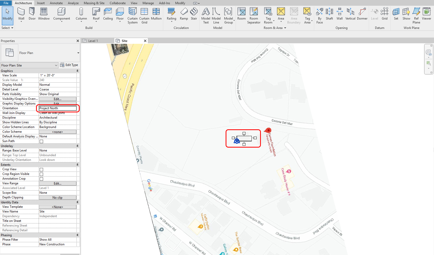
- [STEP 11] Change the view to [TRUE NORTH] from the [PROPORTIES] for the site plan
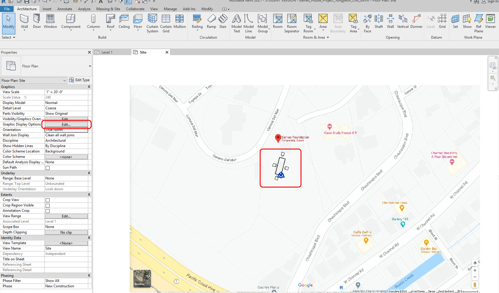
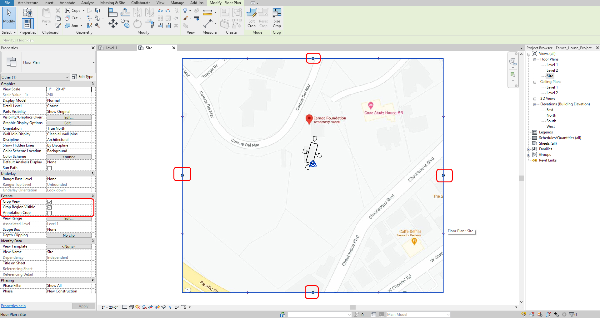
Crop the view to only the site plan area
- [STEP 1] Select [CROP VIEW] and [CROP REGION VISIBLE] from the [PROPERTIES] panel
- [STEP 2] Adjust the region for the view
(CO 4) Find GIS information

A YouTube element has been excluded from this version of the text. You can view it online here: https://iastate.pressbooks.pub/visualgraphiccomm/?p=90
In this tutorial, we will find GIS information from CADMAPPER
- [STEP 1] Open your web browser, go to https://cadmapper.com/
- [STEP 2] Sign up for free if you don’t have the account. Sign on the website.
- [STEP 3] Enter the project address [203 N. Chautauqua Blvd. Pacific Palisades, CA] and search
- [STEP 4] Adjust the area for your project by zooming in and changing the selected area. It is free up to 1 km2
- [STEP 5] Click [CREATE FILE] to generate the 3D model
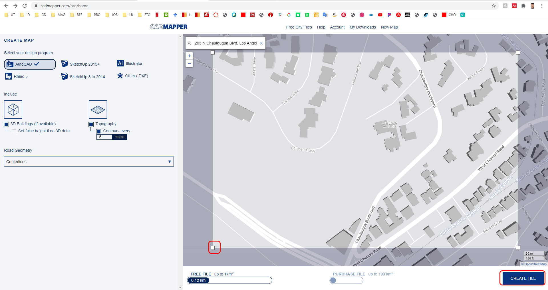
image credit: Screen captured from www.cadmapper.com
- [STEP 6] You can see the preview for your confirmation. Click [DOWNLOAD]
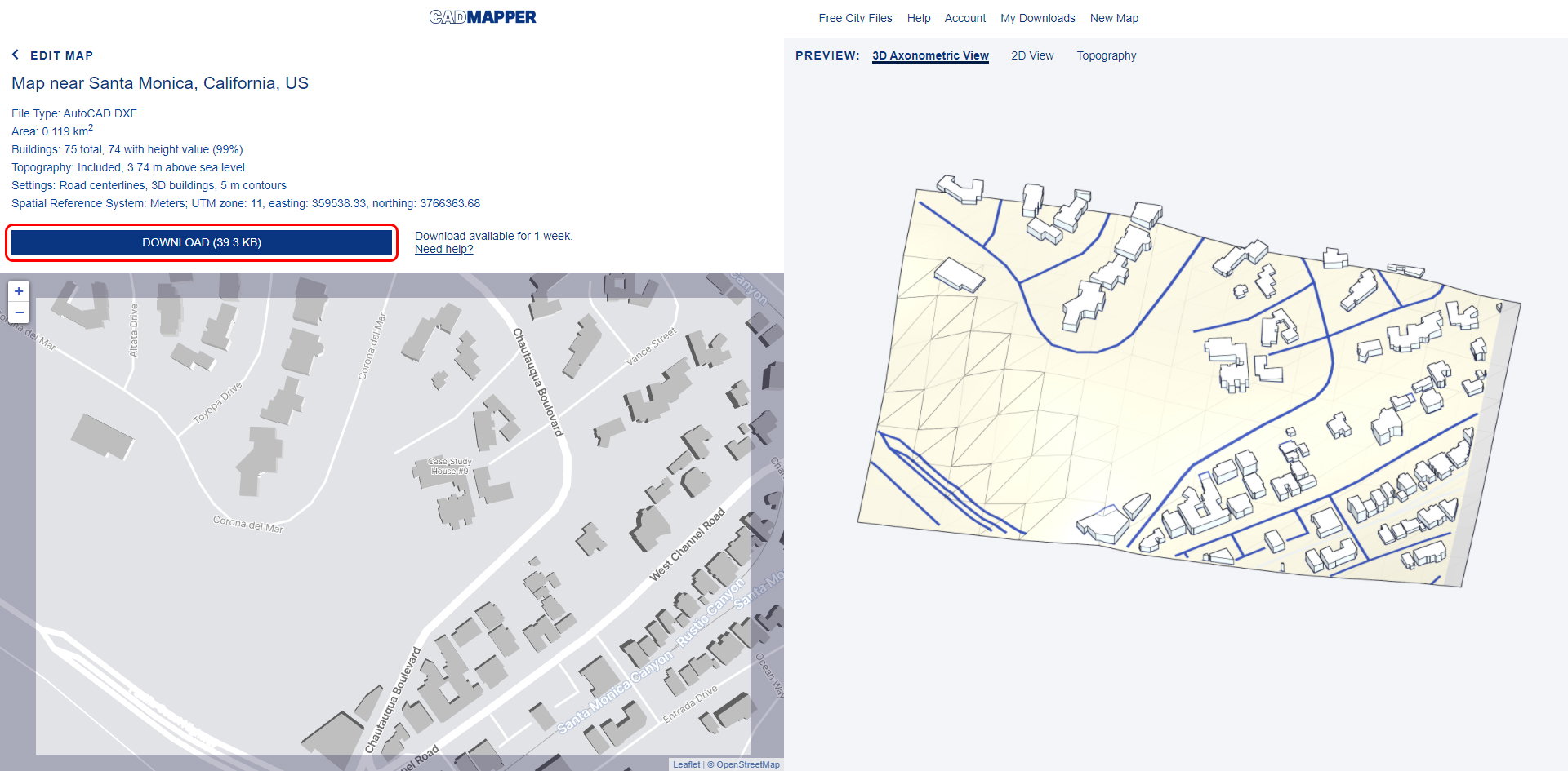
image credit: Screen captured from www.cadmapper.com
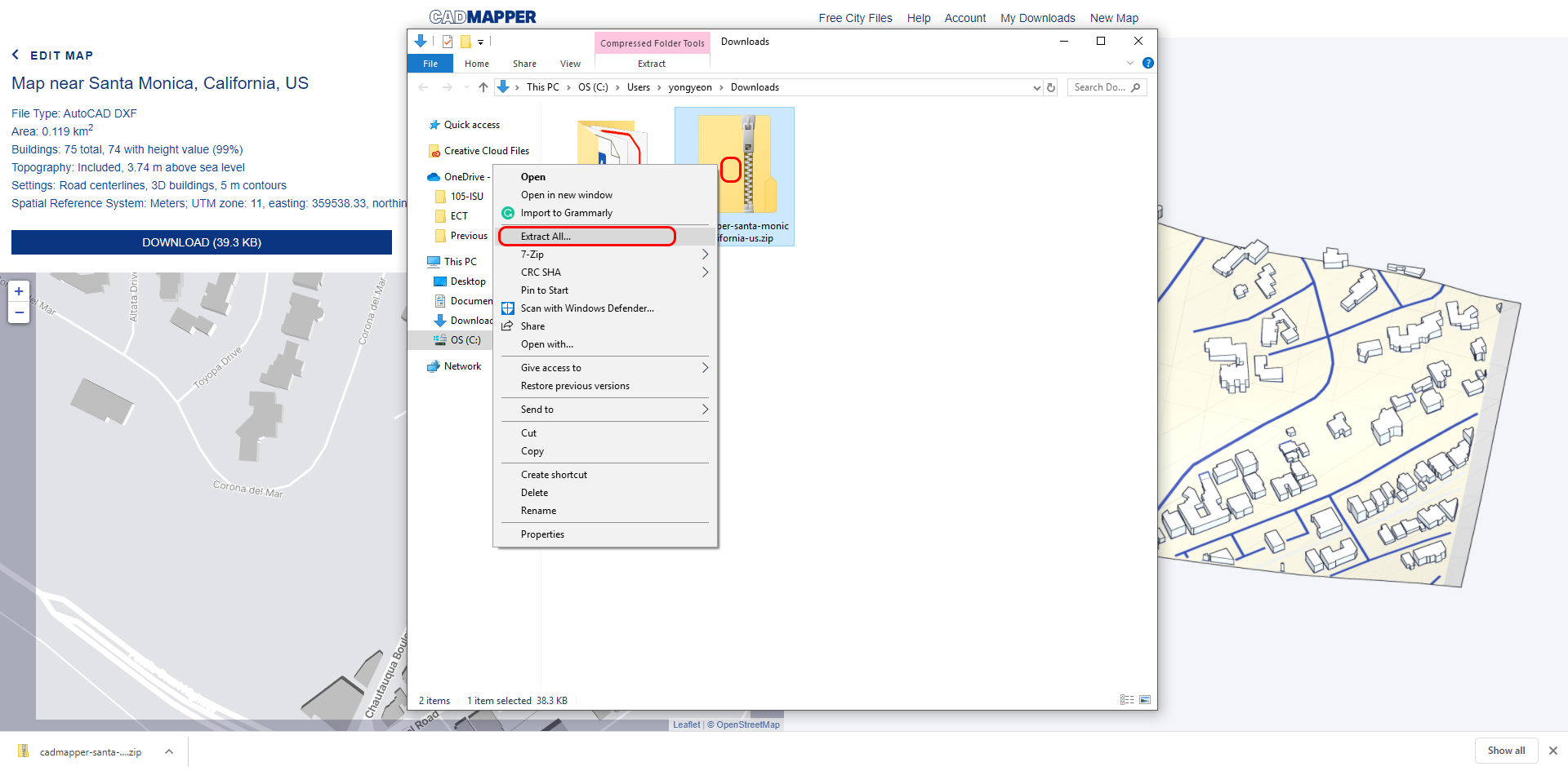
- [STEP 7] Once the download is done, open the folder to extract the zip file
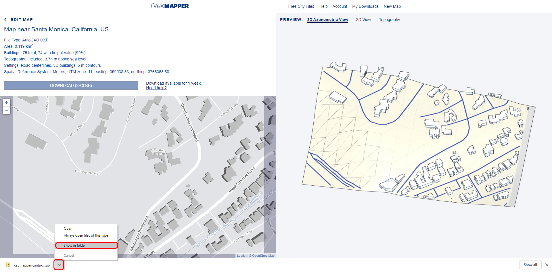
image credit: Screen captured from www.cadmapper.com
- [STEP 8] Extract the zip file
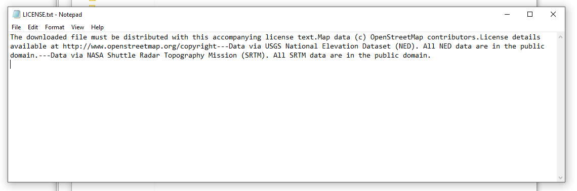
- [STEP 9] Copy the files to your project folder and read the License.txt file before you use the file
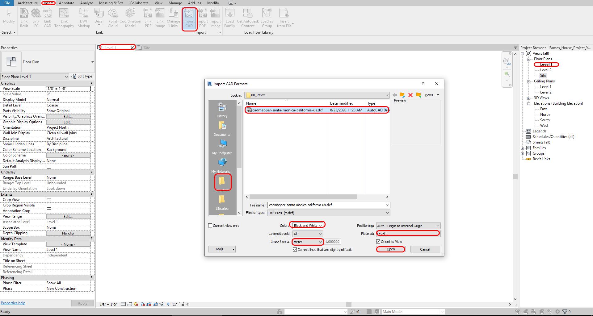
- [STEP 10] Open the LEVEL 1 view
- [STEP 11] Click [IMPORT CAD], from [INSERT] tab, under [IMPORT] panel
- [STEP 12] Open the project folder, change the file type to [DXF files], change colors to [Black and White], change Import units to [meter], Click [OPEN]
- [STEP 13] Move the imported CAD site information to the site. To move the map, you have to unpin before you move the site.
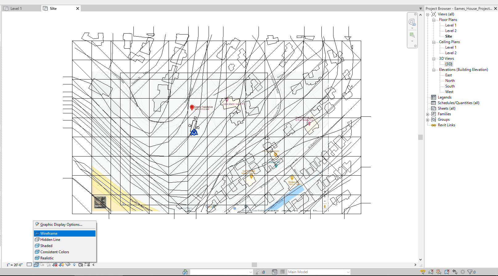
- [STEP 14] Switch the view to [SITE] view, Uncheck [CROP VIEW] from [PROPERTIES]
- [STEP 15] Rotate the imported CAD site map to match the imported GOOGLE MAP (75.56 degrees clockwise)
- [STEP 16] Move the imported CAD site map to match the imported GOOGLE MAP.
- To move correctly, you can switch the graphic display option to [WIREFRAME]
- Refer to other building locations and road locations to get the right location aligned
- [STEP 17] Open [WEST] view
- [STEP 18] Move the imported CAD site map to match the building level 1
- You can type the Base Offset or manually move to match
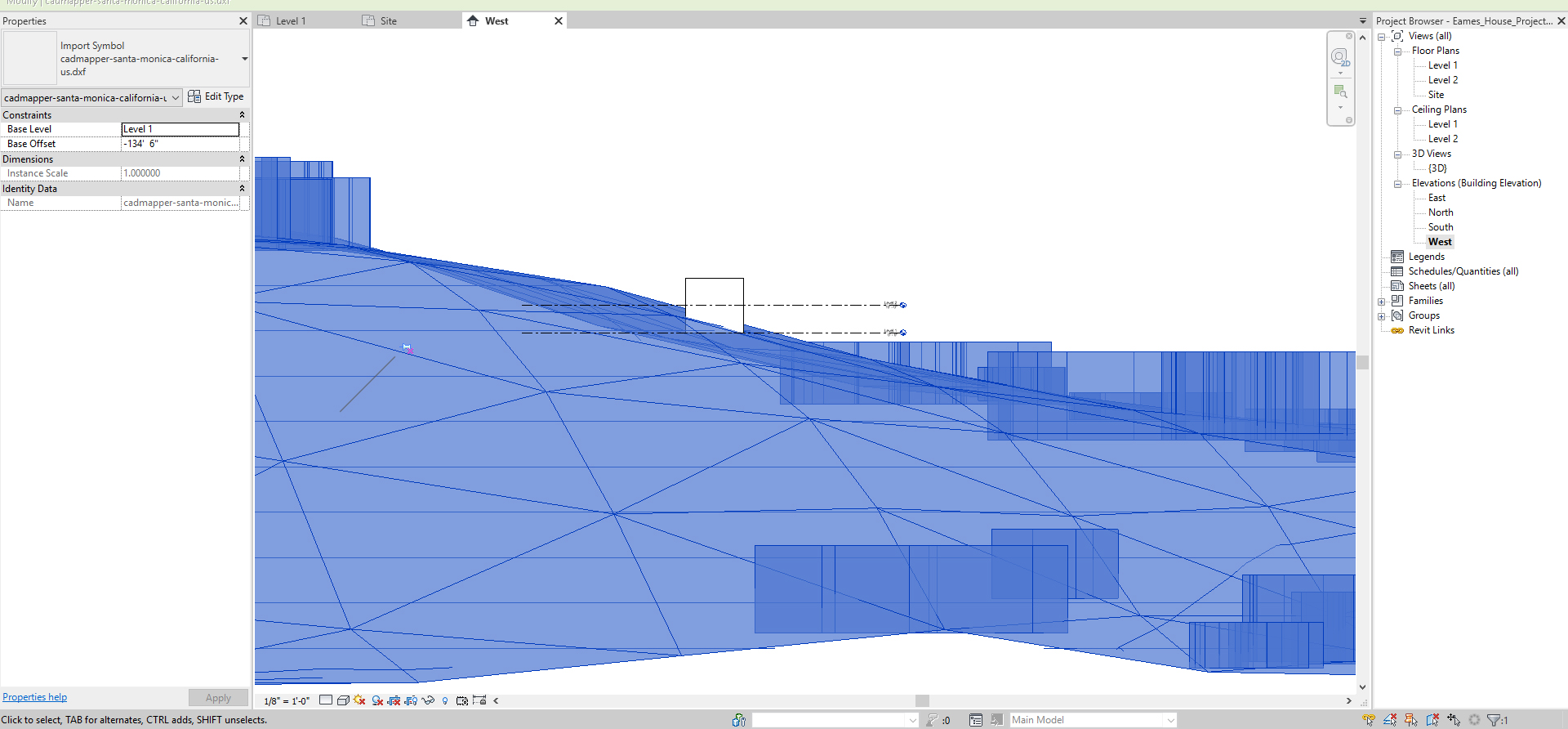
- You can type the Base Offset or manually move to match
(CO 5) Add & Edit Site – Topo surface, roads, side works, property line, building pod, surrounding buildings, and trees

A YouTube element has been excluded from this version of the text. You can view it online here: https://iastate.pressbooks.pub/visualgraphiccomm/?p=90
Create a TOPO SURFACE
Note, Building sight might be completely flat or with little level change. Please try the TOPO SURFACE tool to make the site model.
- [STEP 1] Select [TOPOSURFACE], from [MASSING & SITE] under [MODEL SITE]
- [STEP 2] Select [CREATE FROM IMPORT], from [MODIFY/EDIT SURFACE] under [TOOLS]
- [STEP 3] Select [SELECT IMPORT INSTANCE]
- [STEP 4] Select the imported CAD site map
- [STEP 5] Only check [COUNTOURS] from the ADD POINTS FROM SELECTED LAYERS] window
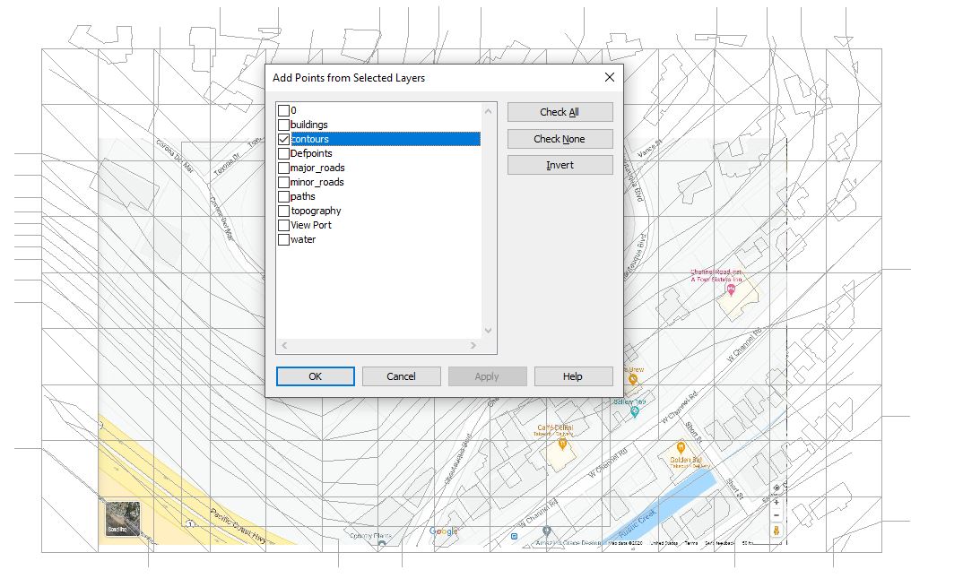
- [STEP 6] Adjust point locations if needed
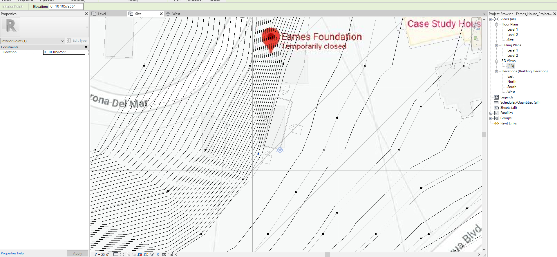
- [STEP 7] Click the green check to complete the topo surface tool
Edit TOPO SURFACE
- [STEP 1] If you want to edit the topo surface, select the topography and select [EDIT SURFACE]
- [STEP 2] If you want to add the point, use [PLACE POINT]
- [STEP 3] If you want to remove the point, select the point and press the [DELETE] key
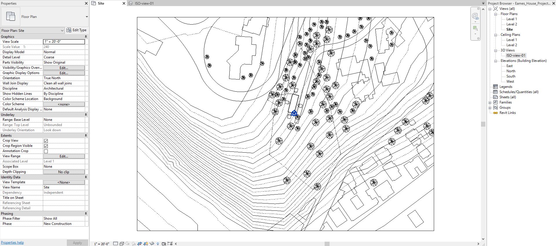
Topography line setting
- [STEP 1] Select [SITE SETTING] from [MASSING & SITE] tab, under [MODEL SITE].
- It is a small arrow on the panel
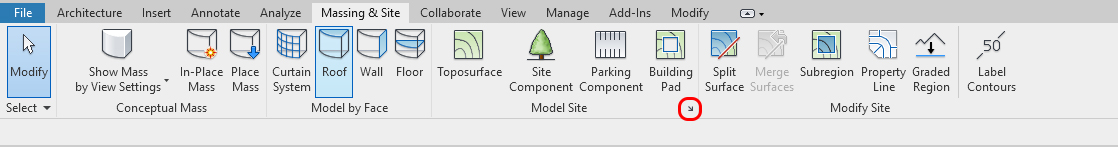
- It is a small arrow on the panel
- [STEP 2] Set your topo lines
The increment number depends on your site map scale and how much detail you want to express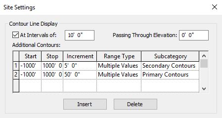
- [STEP 3] Select [EDIT] for [VISIBILITY/GRAPHICS OVERRIDE]
Find [TOPOGRAPHY]
PRIMARY CONTOURS – SOLID / SECONDARY CONTOURS – DASH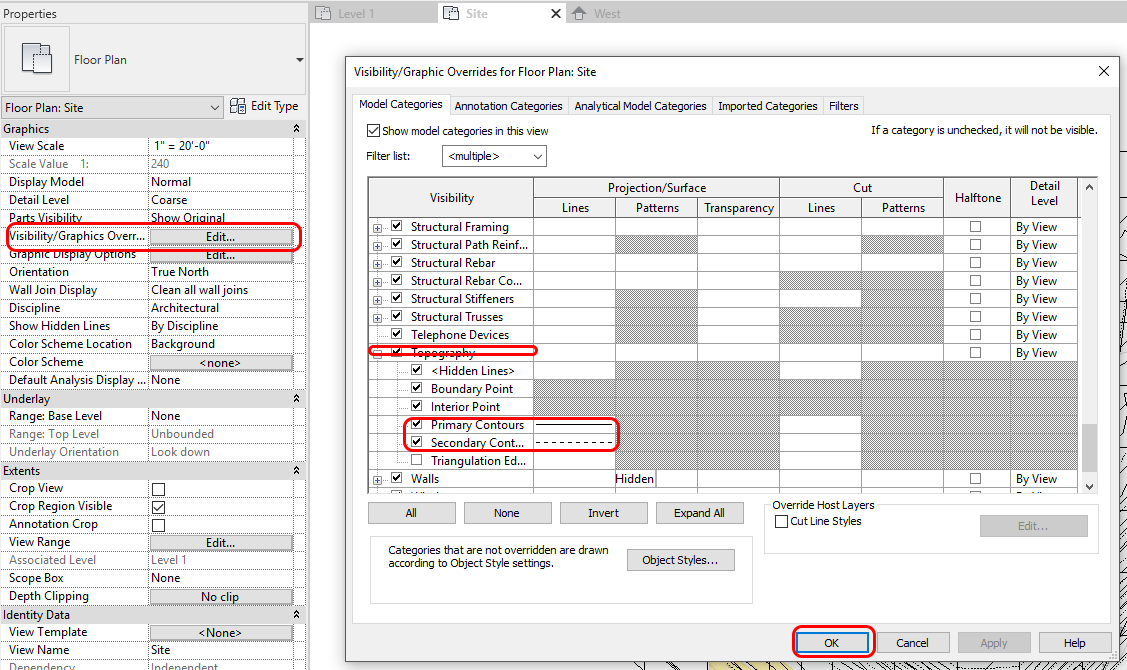
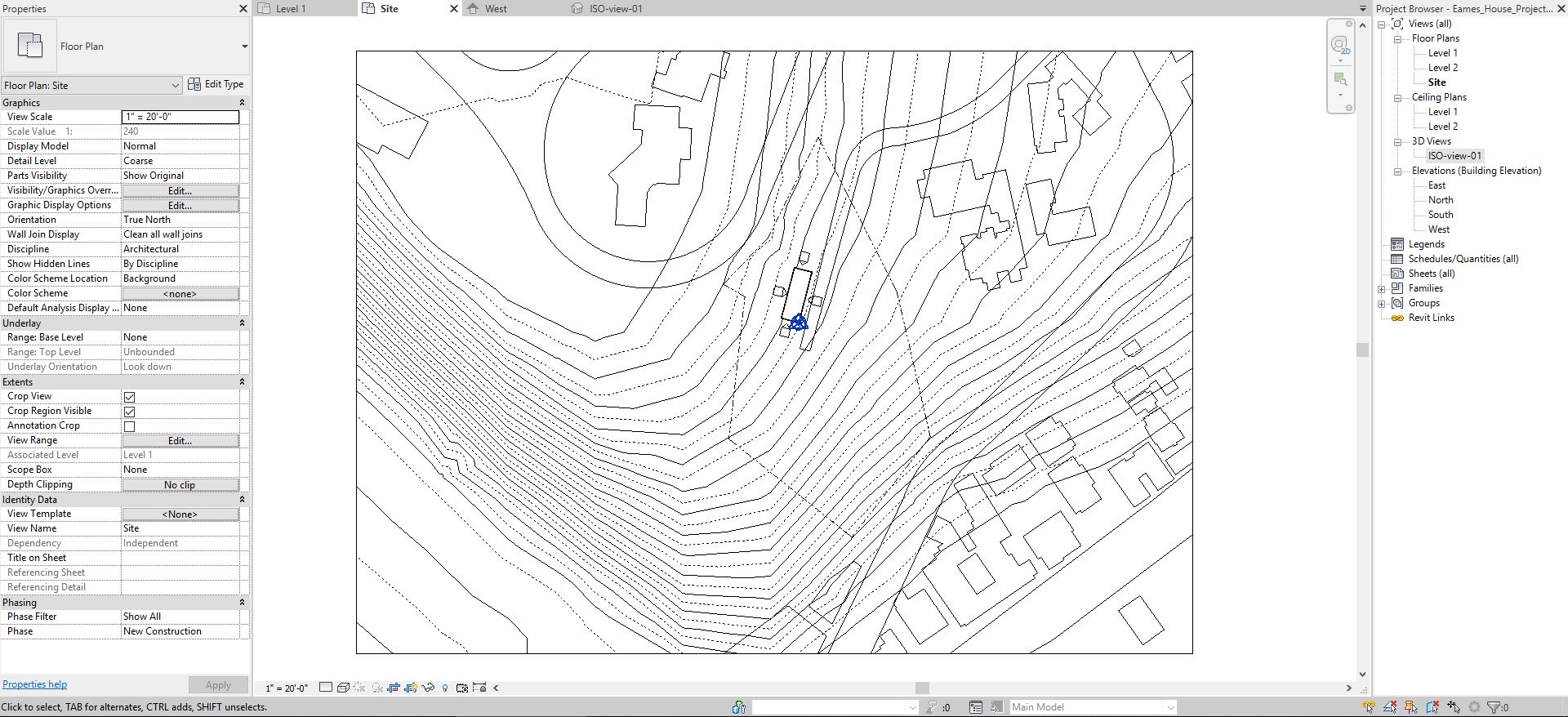
Clean up the imported CAD map
- [STEP 1] Select the imported CAD map
- [STEP 2] Click [DELETE LAYERS] from [MODIFY], under [IMPORT INSTANCE]
- [STEP 3] Check all except [BUILDING]
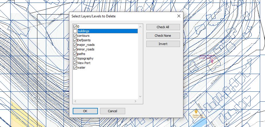
- [STEP 4] Click [OK] to finish the command
- [STEP 5] Check [CROP VIEW] to see only the region inside
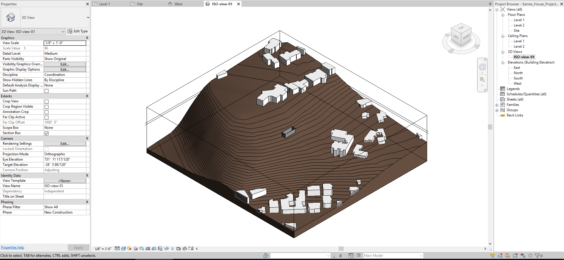
Confirm your topo in 3D
Revit is BIM software. Your 2D drawings can show in 3D. It is wise to double-check in 3D view while you build your model
- [STEP 1] To create a 3D view, click the 3D view on the top of the program
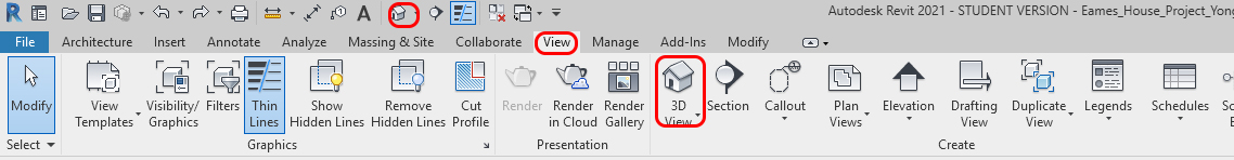
- [STEP 2] Once you click the 3D view, the 3D view will automatically open. To refer back to this view, you can open the 3D view on Project Browser by double-clicking. If you want to keep the view, you must rename the 3D view. For example, ISO-view-01
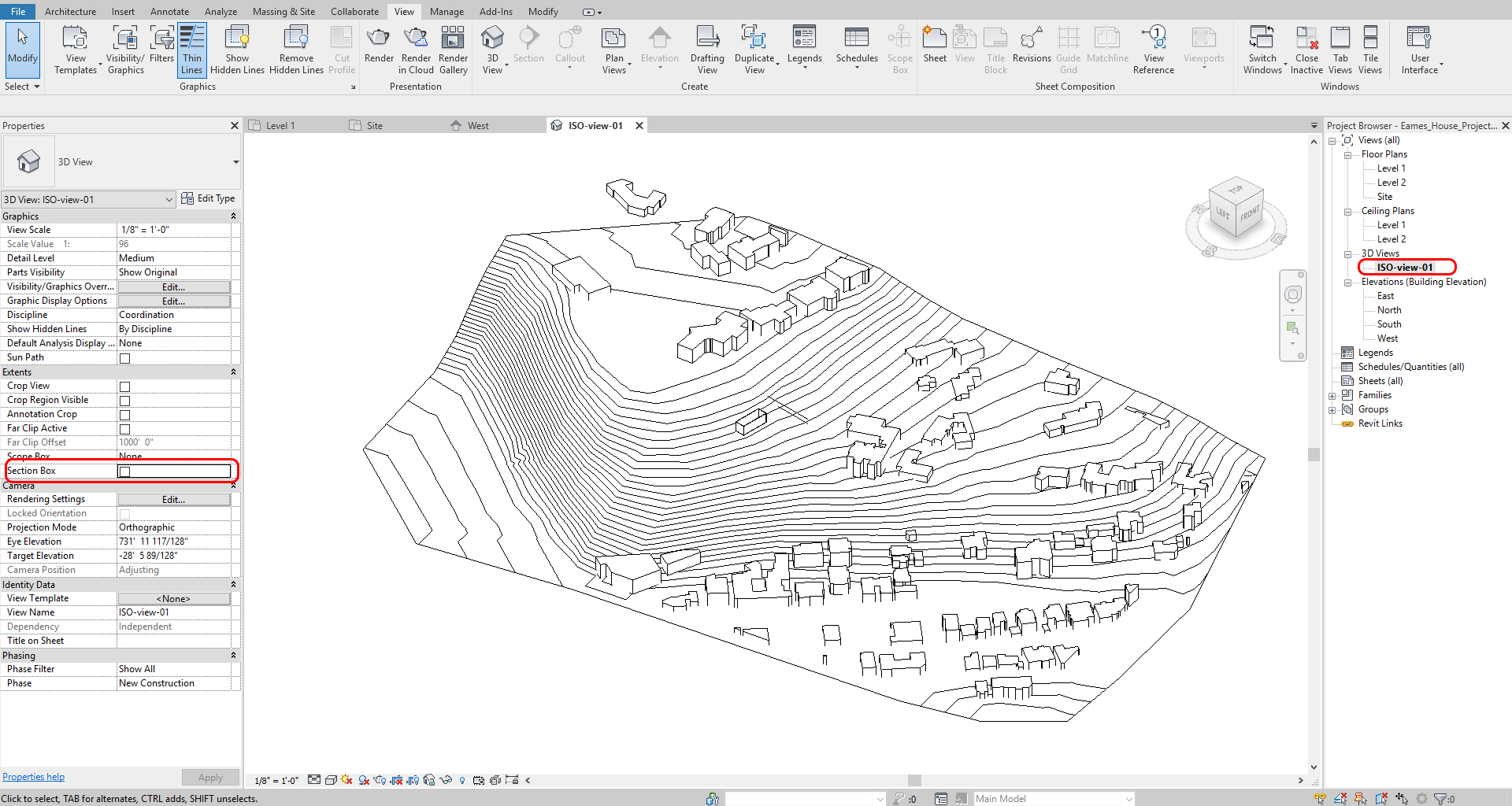
- [STEP 3] Click [SHADED] to see the color
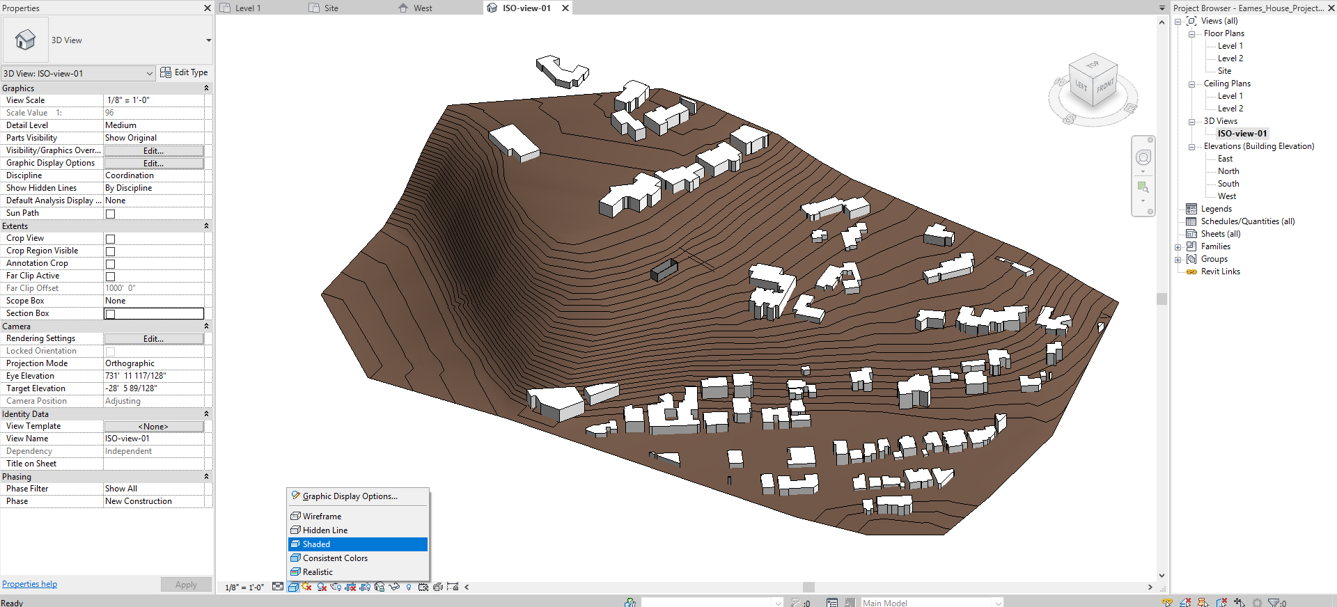
- [STEP 4] Check [Section box] on the Properties and adjust the Section box by adjusting the blue arrow
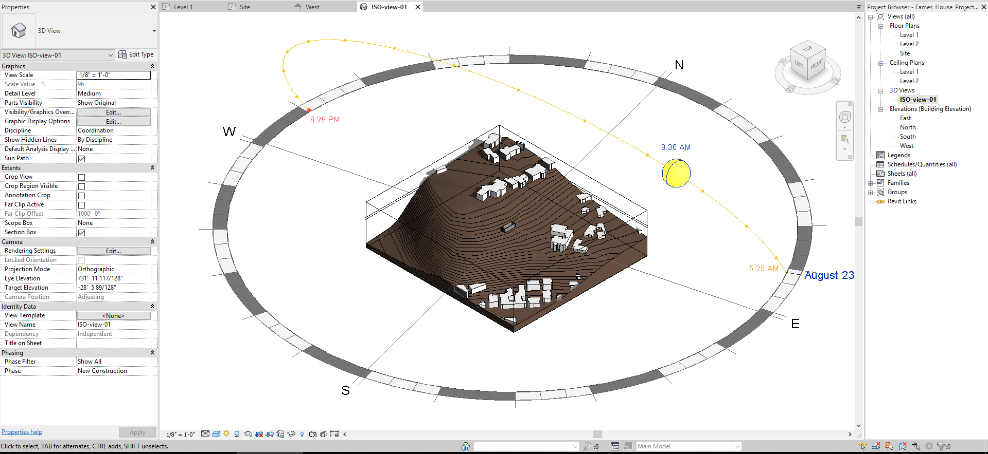
- [STEP 5] Click [Sun path On]
- [STEP 6] Click Shadow
- [STEP 7] Now you can simulate the sun path by drag and dropping the sun
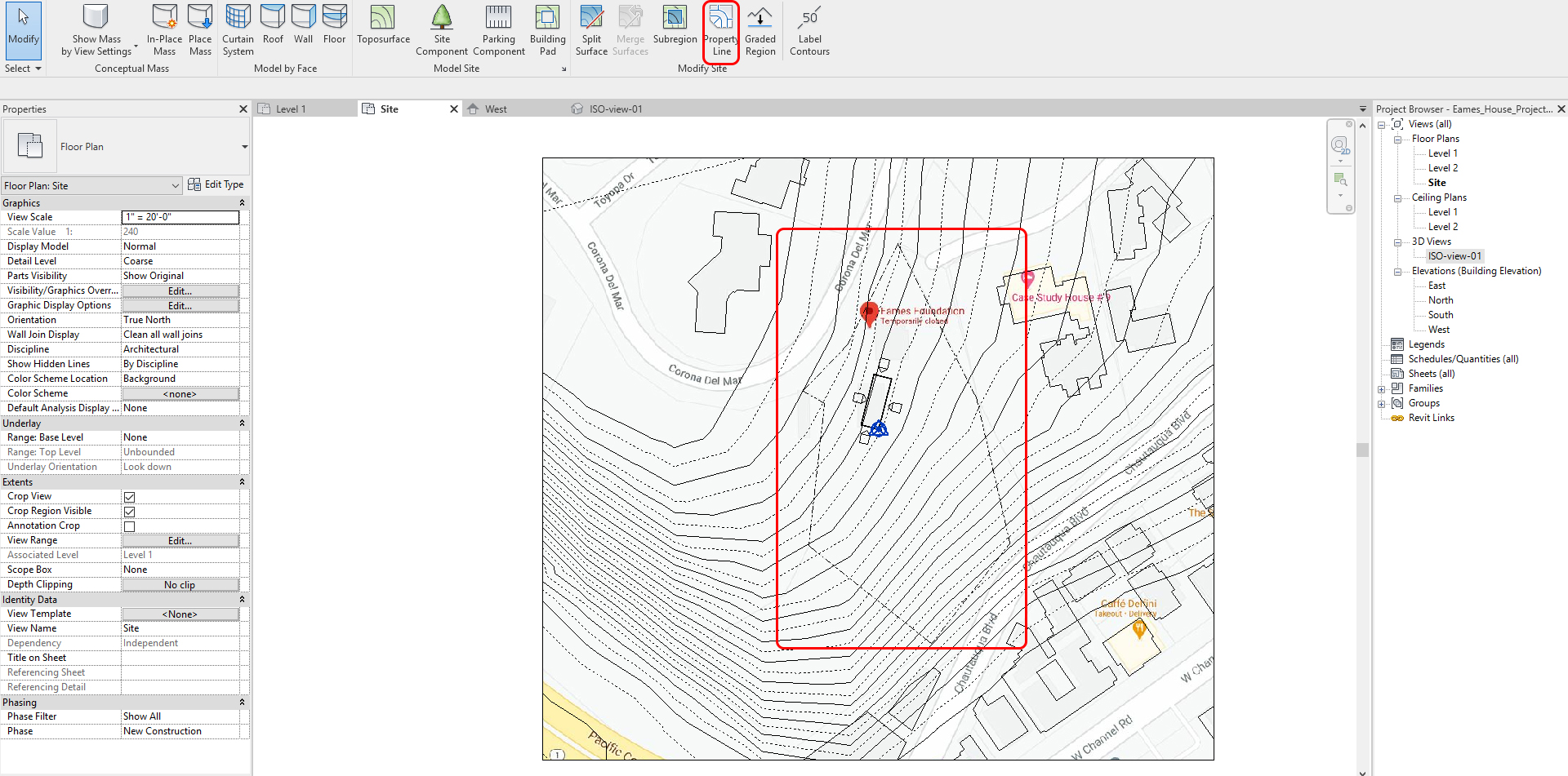
Create Building Pod & Property line
For the building pod and property line, you should hide the Topo image by clicking the image, and mouse right-click and select [Hide in view] > [Elements]
- [STEP 01] Go to Site & massing tab – Click [Building Pad]
- [STEP 02] Make sure your building pod is on level 1
- [STEP 03] Draw a closed line
- [STEP 04] Go to Site & massing tab – Click [Property Line] – Create by sketching
- [STEP 05] Use Google Map to draw the property line. Draw a closed line
Create Roads
- Go to Site & massing tab – Click Subregion
- Draw a closed line
Create Neighborhoods (Trees)
- Go to Site & massing tab – Click Site component
Once you finished your site plan, you should hide the Google image.
SAVE the file before closing the application.
Save in a different location for the backup (e.g., a cloud folder)
 References
Archibald & Fraser Architects Ltd. (2012, November 10). Lochaber Centre Site Plan.jpg. Retrieved October 22, 2020, from https://commons.wikimedia.org/wiki/File:Lochaber_Centre_Site_Plan.jpg
Site Planning Process Chesterfield County, Virginia Planning Department. Accessed 11 Feb 2009. Archived March 29, 2009, at the Wayback Machine
Google. (n.d.). Google map. Retrieved October 23, 2020, from https://www.google.com/maps
Worldwide map files for any design program. (n.d.). Retrieved October 23, 2020, from https://cadmapper.com/