
15: Chapter 15. Add/edit model-in-place components and edit family
- Page ID
- 13196

 Session Objectives
Upon completing this session, students will be able to:
(CO 1) Add/Edit Furniture families
(CO 2) Add/Edit Model-in-place components – Custom casework
(CO 3) Add/Edit a New Family – Furniture
 Session Highlights
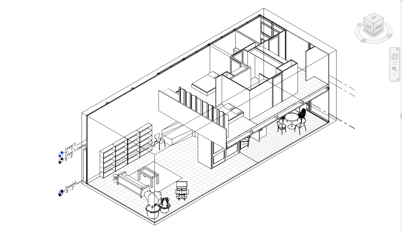
At the end of the session, students can create the graphics below.
 Lecture Contents
(CO 1) Add/Edit Furniture families
A YouTube element has been excluded from this version of the text. You can view it online here: https://iastate.pressbooks.pub/visualgraphiccomm/?p=102
For construction documents in Revit, furniture can be mainly categorized into two main areas. One is a product, which includes custom furniture and manufacture-made furniture, and the other is a contractor (carpenter) made built-in furniture or millwork.
- We typically use [PLACE COMPONENTS] a Revit family for custom furniture and manufacture-made furniture because it will be used multiple times. It includes millwork like Revit Countertop, Shelf, Cabinets, and so on.
- We typically use [MODEL-IN-PLACE] for contractor made built-in furniture or millwork because it will be used only once for the specific space only.
Revit Furniture [PLACE COMPONENTS]
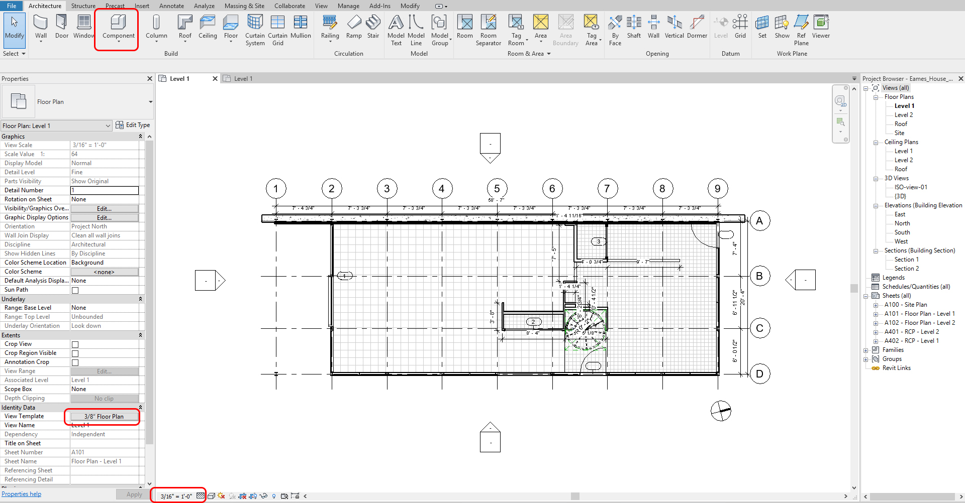
- [STEP 1] Open a Floor Plan – Level 1 view from Project Browser
- [STEP 2] You may change the scale of the view because we changed the drawing scale to fit on an 11in X 17 in sheet. I changed the drawing scale from 3/32” to 3/16”
- [STEP 3] Click [COMPONENTS] (CM) from [ARCHITECTURE] tab
- [STEP 4] You will find furniture (or any components-lighting fixture, plumbing, case work-sink, appliances, plants) from [Properties] palette that you want to put in the floor plan. If you do not find the furniture from the panel, you must click [LOAD FAMILY] from [MODIFY/PLACE COMPONENT] tab and find the furniture family you want to add from the Library folder or the websites from Session 14
- BimObject https://www.bimobject.com/en-us
- Revit City https://www.revitcity.com/index.php
- BIM Smith https://market.bimsmith.com/
- NBS National BIM Library https://www.nationalbimlibrary.com/en/
- Manufacturers’ website
TIPS.
For your Floor plan, you do not need to find the exact furniture that you want to use. You may use the Revit furniture family for your floor plan as a placeholder. Do not waste time to add all objects (like books, decorative pieces for perspectives) that are not showing on your floor plan. For your perspective views and renderings, you would be better to find the most accurate Revit family file. If you cannot find the Revit family file, find the SketchUp file and use it for your rendering.
- [STEP 5] Place the furniture families on your floor plan. Make sure the Level is what you want.
- [STEP 6] Use [Space bar] on your keyboard to rotate the family.
To move/rotate/align/copy/mirror the furniture, click the furniture that you want to move/rotate and then click [MOVE] (MO), [ROTATE] (RO), [align] (AL), [COPY] (CO), or [MIRROR] (MM) from [MODIFY/FURNITURE] tab - [STEP 7] Also, you can use [ALIGNED DIMENSION] (DI) from the [ANNOTATION] tab
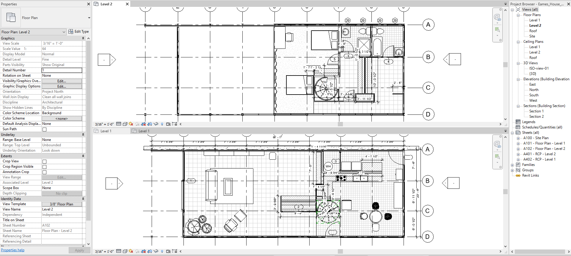
- Complete all furniture placement
(CO 2) Add/Edit Model-in-place components – Custom casework

A YouTube element has been excluded from this version of the text. You can view it online here: https://iastate.pressbooks.pub/visualgraphiccomm/?p=102
Create Model in Place components (Alcove seating)
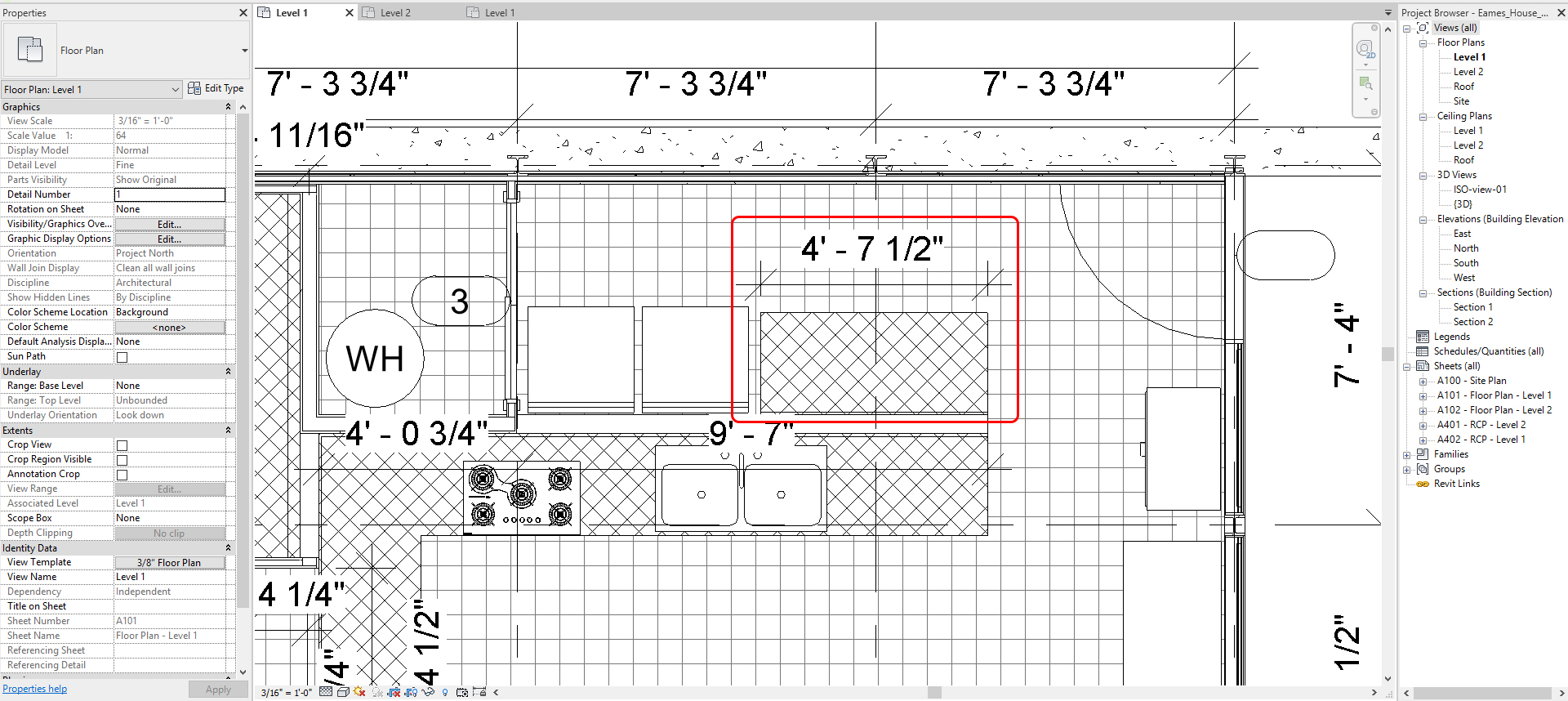
- [STEP 1] Open a Floor Plan – Level 1 view from Project Browser
- [STEP 2] You may turn on the reference CAD plan/Imported image to see the size of the Alcove setting or turn on [HIDDEN ELEMENTS] if it is hidden and unhide the category
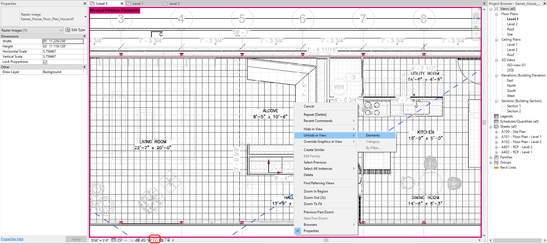
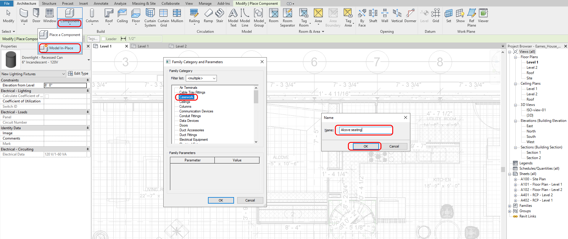
- [STEP 3] Click Component small black arrow and click [MODEL IN PLACE] from [ARCHITECTURE] tab
- [STEP 4] You will need to select the most relevant Family Category. For the Alcove Seating, [CASEWORK] is the most appropriate category. Click [OK]
- [STEP 5] make a name for the component [Alcove seating].
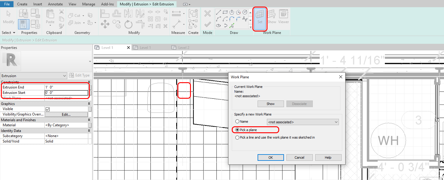
- [STEP 6] To draw lines/models, you must set/confirm the [WORK PLANE] first
- Click [SET] from [CREATE] tab
- You can select the work plane with the name or pick a plan. Make sure this will be the base plane that you work
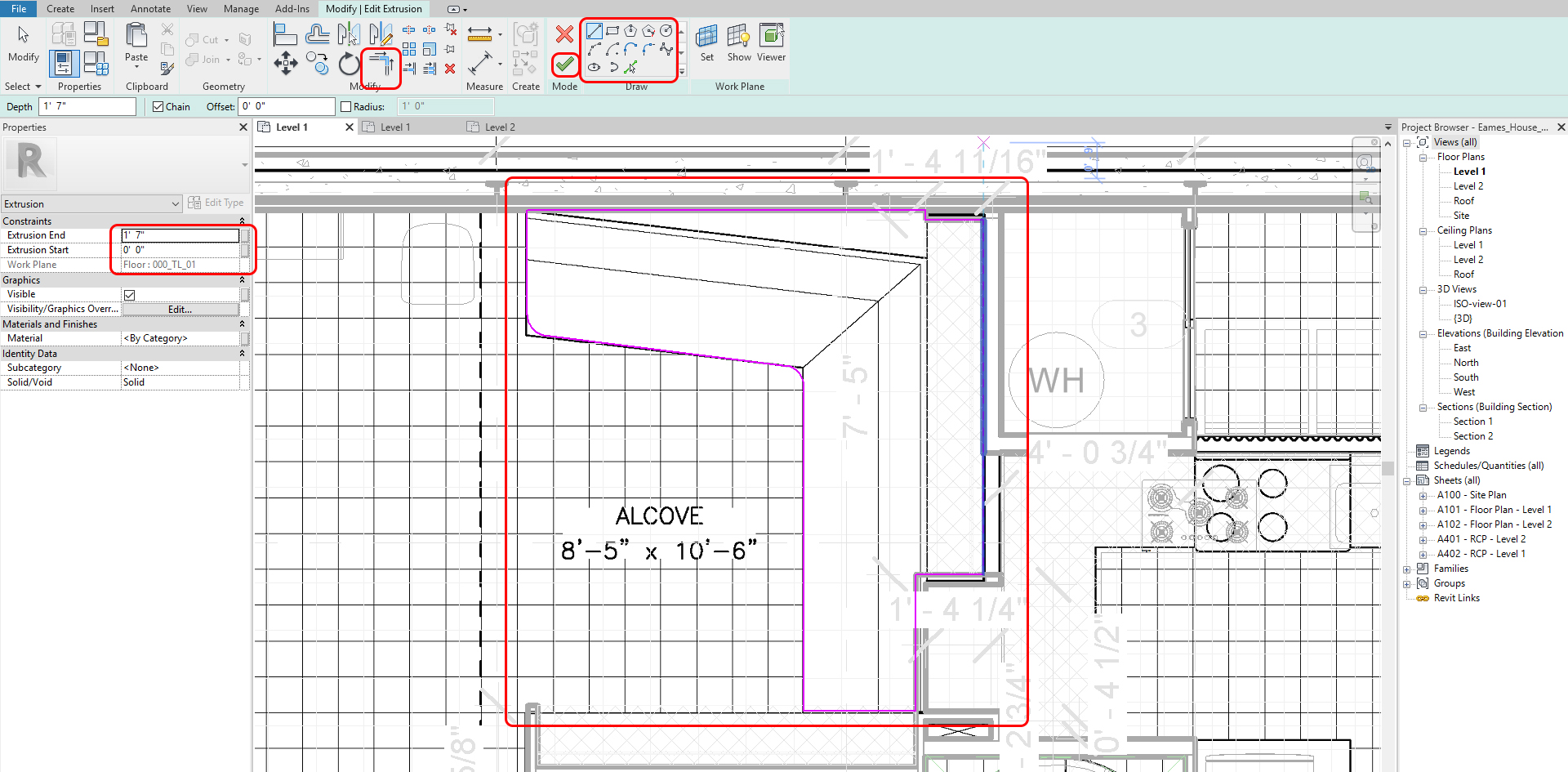
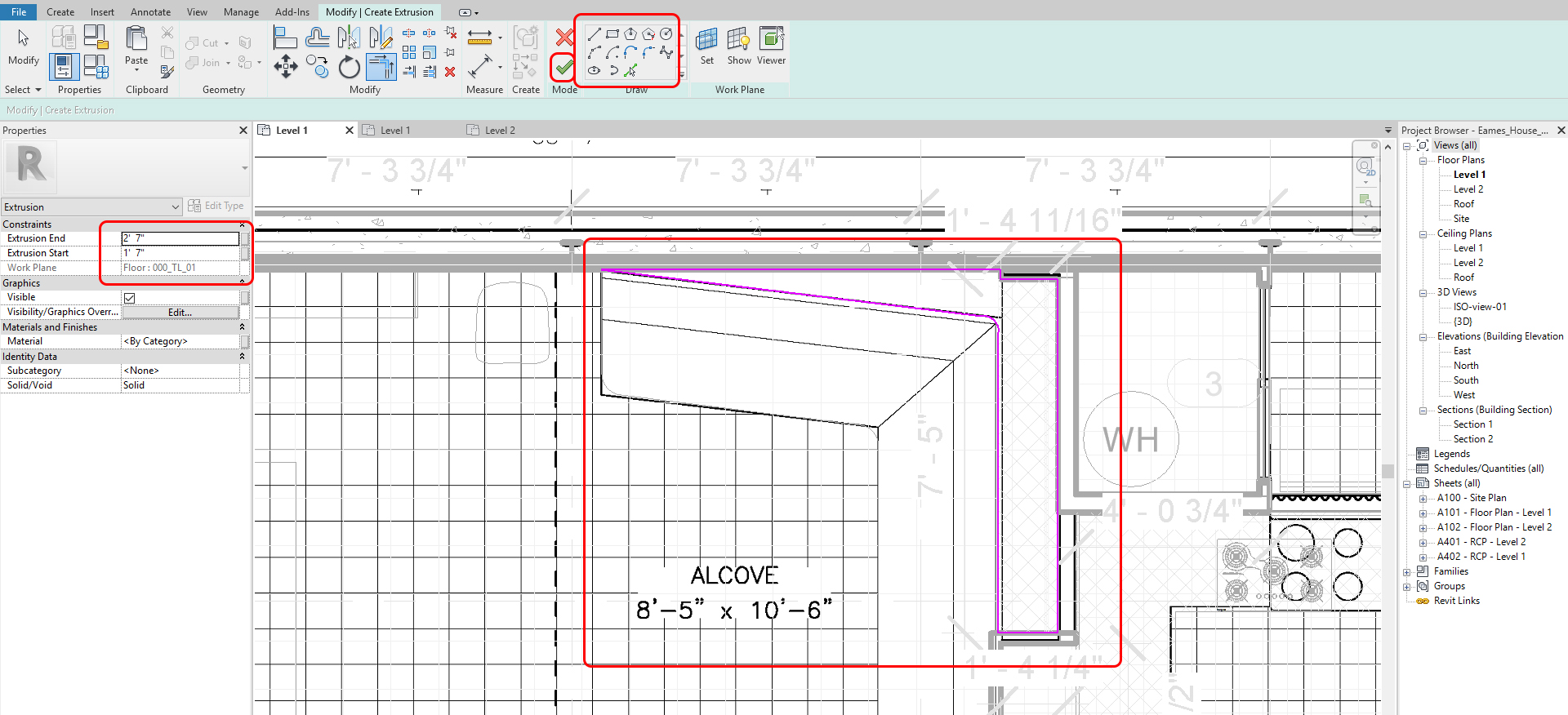
- [STEP 6] You can make models with the Forms tool
- For the alcove seating, click [EXTRUSION] and draw lines with the [DRAW] tool
- The line must be closed. You may use [TRIM] (TR) to make it closed
- Double-check the Extrusion End and Extrusion Start
- Click the [GREEN CHECKMARK] to finish the drawing
-
- For the upper part, you will create the upper part in the current [MODEL-IN PLACE COMPONENT]
- If you want to try other Forms, you are welcome to try and practice.
- Use the [VOID] tool and Cut tool to subtract a form from other forms (s)
- Click Extrusion > Draw lines > make sure the extrusion End and Start > Click [GREEN CHECKMARK]
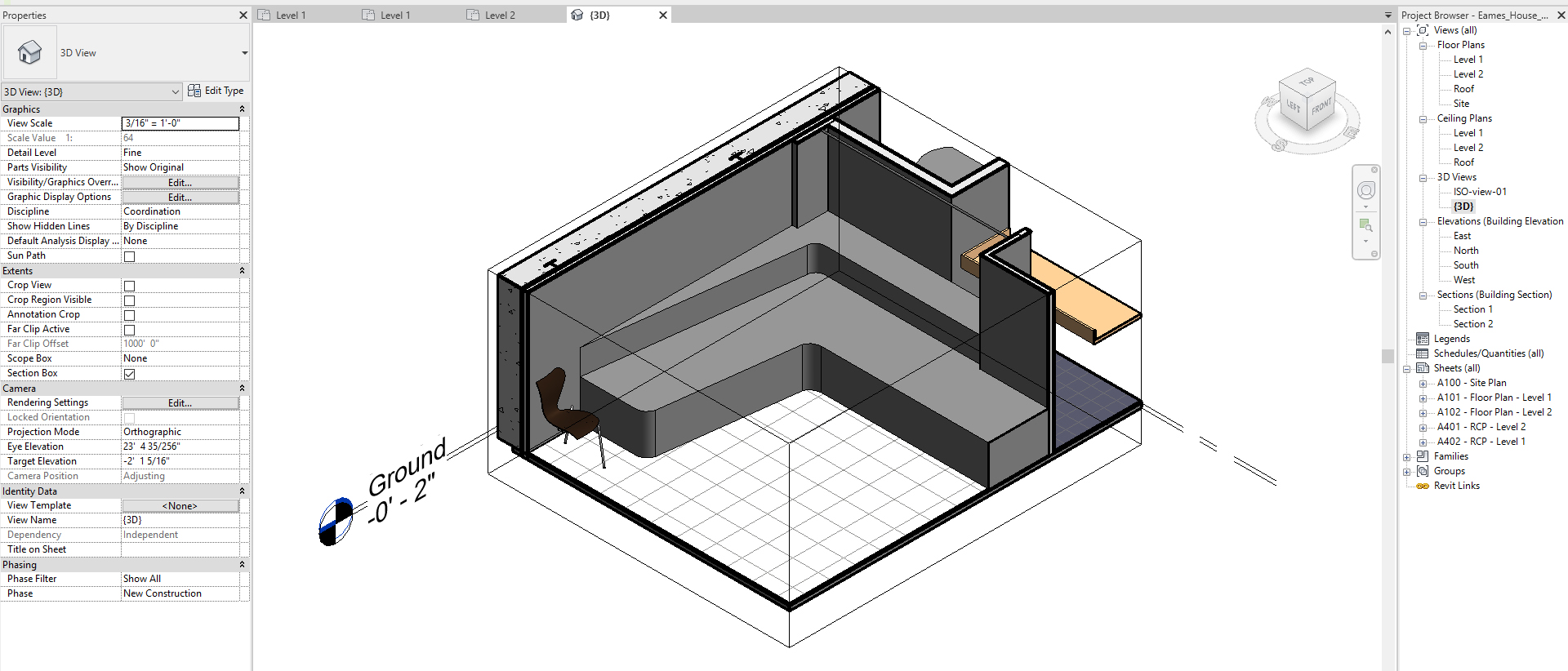
- If the model is not showing, please check on your ISO view and change the [WORK PLANE]
- Once all forms created, you will click the [GREEN CHECKMARK] to Finish Model
- Complete the casework
(CO 3) Add/Edit a New Family – Furniture
A YouTube element has been excluded from this version of the text. You can view it online here: https://iastate.pressbooks.pub/visualgraphiccomm/?p=102
In this tutorial, I will demonstrate how to create a simple furniture family in Revit. We will use Eames Walnut Stool information from https://www.hermanmiller.com/products/seating/stools/eames-walnut-stools/
To create a new family file (Model it will be used multiple times)
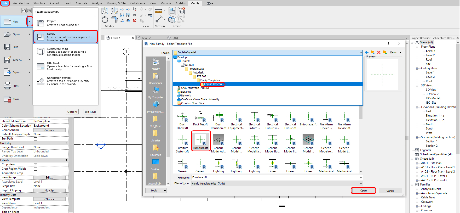
- [STEP 1] Click [FILE] > [NEW] > [FAMILY]
- [STEP 2] Find [Furniture.rft] in the Select Template File browser and Click [OPEN]
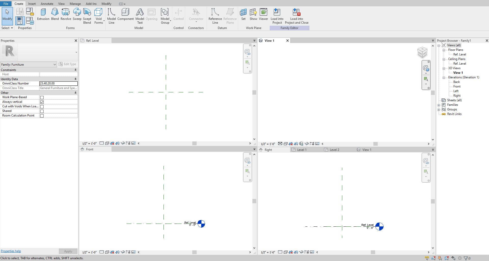
- [STEP 3] It will automatically open these four windows. Before you start, save the family file to your project folder.
- [STEP 4] I recommend you make the view tile (WT) and Zoom All (ZA) see all views. You will pick a view [REFERENCE LEVEL], or [FRONT] view depends on what you want to make.
- [STEP 5] To draw the stool, you will use [REVOLVE] to draw this stool
- [STEP 6] Before you draw a revolving line, you will need [REFERENCE PLANES] to know the Height and Width. Click [REFERENCE PLANE] from the [CREATE] tab
- [STEP 7] Draw height left, and right reference plane and dimension it
Dimension information from this page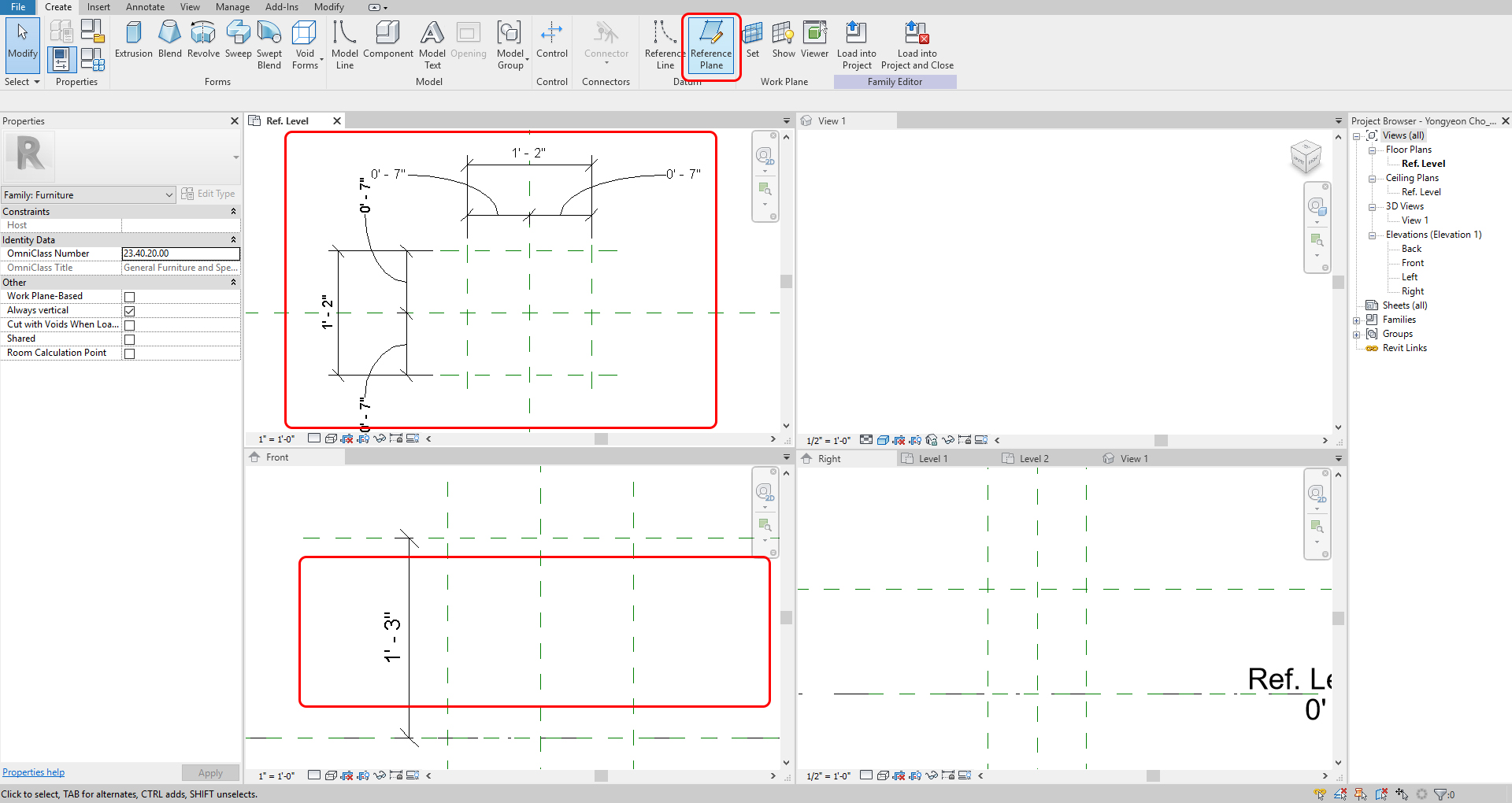
- [STEP 8] On [FRONT] view, Click [REVOLVE] from the [CREATE] tab
- [STEP 9] Draw lines for the Profile (Boundary). The lines are to be closed
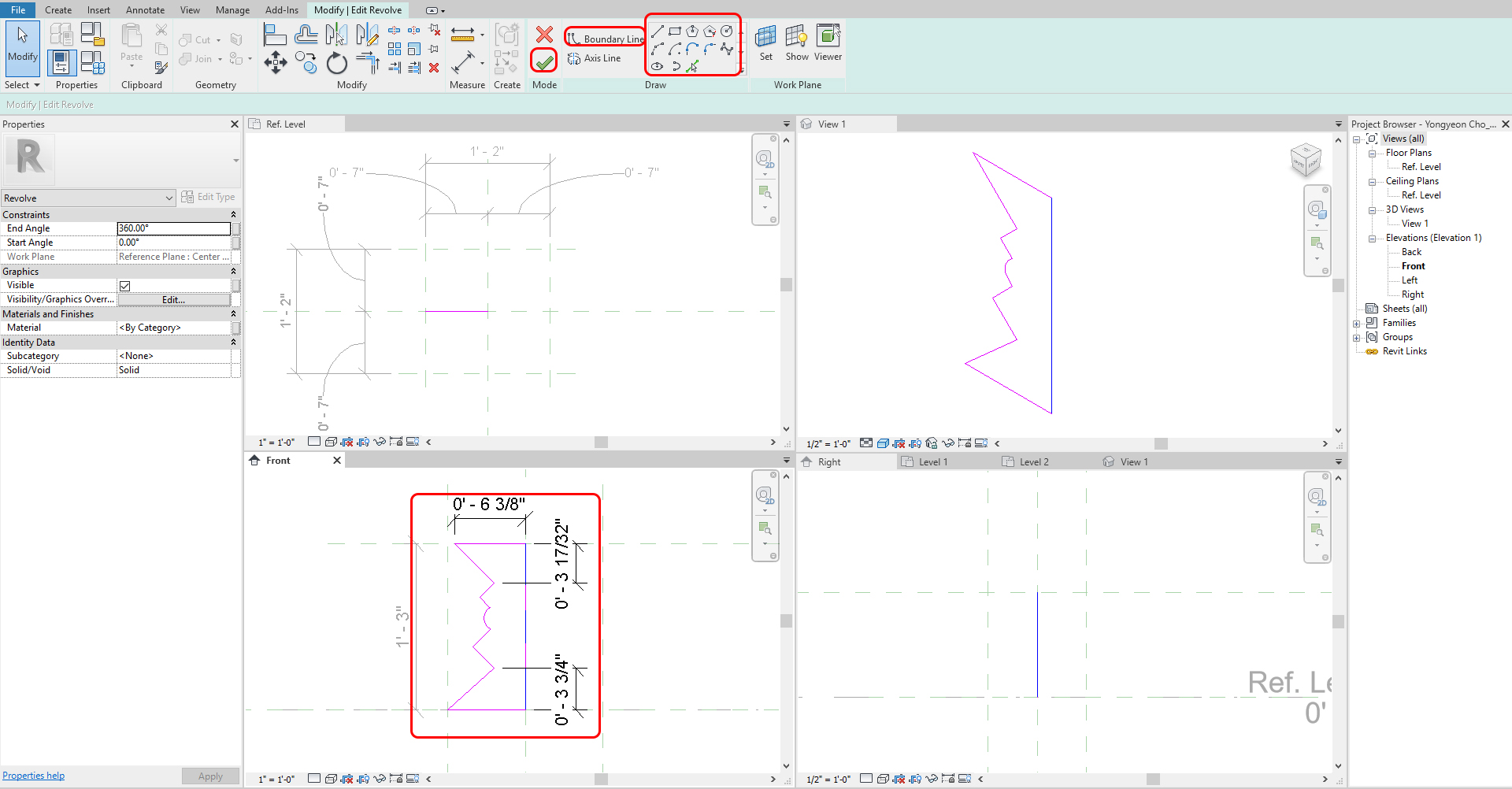
- [STEP 10] Select [AXIS LINE] and pick the centerline
- [STEP 11] Click the [GREEN CHECKMARK] to finish the model
- [STEP 12] If you want to add/subtract any model, you can create it in this model
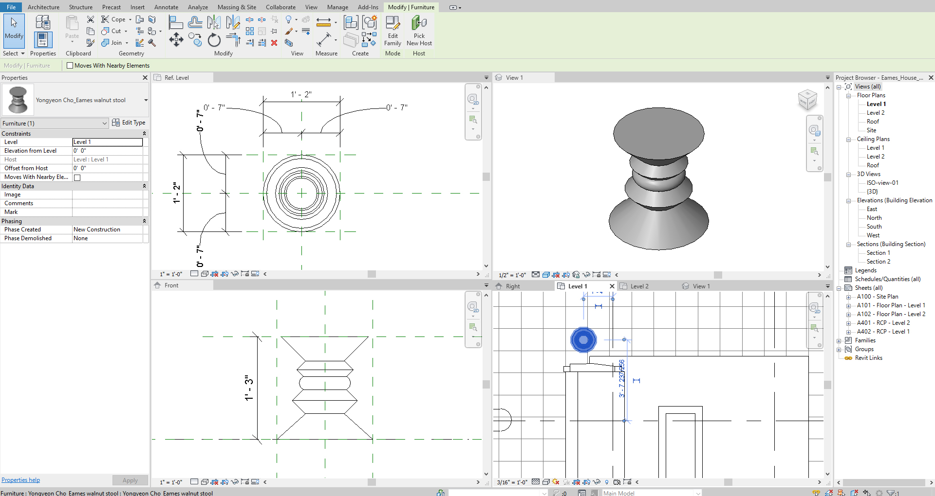
- [STEP 13] Once all your model works are done, save the family file on your project folder.
- [STEP 14] Click [LOAD INTO PROJECT] to your project.
Note. Use Sketchup Model in Revit
Importing SketchUp Files into Revit Tutorial
If you want your Sketchup file in multiple-use, you should make it as a family file.
Sketchup material will not be followed and merged as one material, but I will demonstrate some tips in the next session. Refer to this video
Revit Architecture | Convert SketchUp Models Into Revit(With Materials)
SAVE the file before closing the application.
Save in a different location for the backup (e.g., a cloud folder)
 References
Autodesk.Help. (2018, May 16). Revit Families. Retrieved October 22, 2020, from https://knowledge.autodesk.com/support/revit-products/learn-explore/caas/CloudHelp/cloudhelp/2016/ENU/Revit-Model/files/GUID-4EBB97AD-C7B6-4828-91EB-BC0E99B81E43-htm.html
Eames Walnut Stools. (n.d.). Retrieved October 23, 2020, from https://www.hermanmiller.com/products/seating/stools/eames-walnut-stools/
DWR. (2019, June 12). Eames Walnut Stool. Retrieved October 23, 2020, from https://www.dwr.com/bedroom-bedside-tables/eames-walnut-stool/237.html?lang=en_US
Balkan Architect. (2018, April 12). Importing SketchUp Files into Revit Tutorial. Retrieved October 23, 2020, from https://www.youtube.com/watch?v=4VFK-KEOMZc
M.T.H Revit Tutorials. (2018, May 4). Convert SketchUp Models Into Revit (with Materials). Retrieved October 23, 2020, from https://www.youtube.com/watch?v=k_1g3077jxI