
2.4: Module 10- Viewing 3D Models – Part 2
- Page ID
- 19947

Module 10: Viewing 3D Models – Part 2
Learning Outcomes
When you have completed this module, you will be able to:
- Apply the VSCURRENT command to display 3D surface or solid models in the five predefined visual styles.
- Apply the more advanced options of the 3DORBIT command.
- Use the system variable VPCONTROL to enable the display the Viewport Controls menu and describe how this menu is used to set the current view and orientation of the model.
- Enable the display of the ViewCube and describe how it used to change the display and orientation of the model.
Visual Styles
In the first nine modules, drawing wireframe models was taught. A wireframe model is a real-world 3D object represented by lines, circles, arcs, and/or plines located along the edges of the model. For that reason, you can see right through the model and see objects that would not be visible if the model was surfaced or solid. Think of it as the skeleton of a model.
In Modules 12 to 30, constructing surface and solid models is taught. AutoCAD software comes complete with five predefined visual styles. In this module, viewing surface and solid models using these five styles is covered.
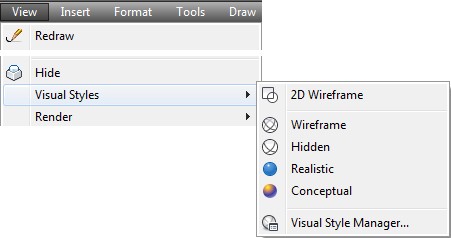
The VSCURRENT command is used to set the current visual style that the model will be displayed. See Figure 10-1. You can change the current visual style as required.

Realistic Visual Style of a Solid Model
AutoCAD Command: VSCURRENT
The VSCURRENT command is used to set the current visual style (shade mode) to be applied to a surface or solid model.
Shortcut: VS

WORK ALONG: Setting the Current Visual Style of a Model
Step 1
Using the NEW command, start a new drawing using the template: 3D Layout English.
Step 2
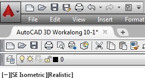
Save and name the drawing: AutoCAD 3D Workalong 10-1.
Step 3
Enter the UNITS command. In the Units dialogue box, set the Insertion Units to Inches. With the current UCS set in World, use the INSERT command to insert the block:
AutoCAD 3D Workalong 10-1 at the coordinates 0,0,0. Explode the block. Be careful to only explode it once.
Step 4
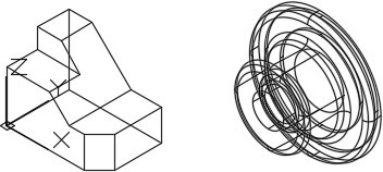
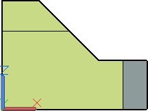
Set the current view to SE Isometric. Your model should now appear as shown in the figure. (Figure Step 4)
Step 5
Change the layer of both solid models to layer: Model.
Step 6
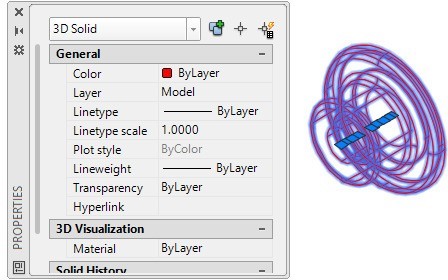
You should now have two solid models. To check this, open the Properties window and select one of the solid models. When selected, the object type in the top box of the Properties windows should indicate that the object is a 3D Solid. If the object type is anything else, exit and delete the drawing. Start this workalong again from Step 1. Be careful when using the EXPLODE command to explode the block only once. (Figure Step 6)
Step 7
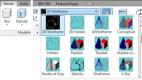
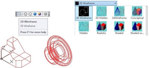
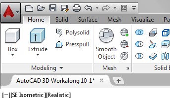
If you are using Toolbars menus, enable the Visual Styles toolbar. If you are using the Ribbon Menus, click the Home tab. Enable the 2D Wireframe visual style icon. You can tell when the current visual style is 2D Wireframe by the appearance of the UCS icon. (Figure Step 7)
Step 8
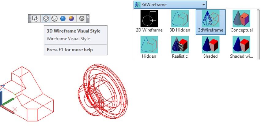
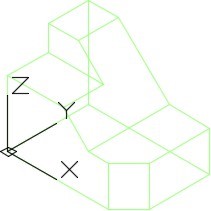
Click the 3D Wireframe visual style icon. You can tell when the current visual style is 3D Wireframe by the appearance of the UCS icon. (Figure Step 8)
Step 9
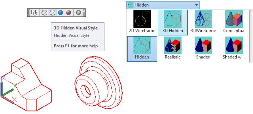
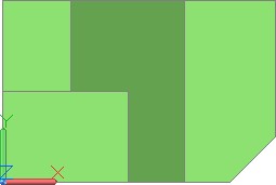
Click the 3D Hidden visual style icon. Note how when the current visual style is 3D Hidden, the model appears solid and only displays the visible objects. (Figure Step 9)
Step 10
Change the layer of both solid models to layer: Solid 1.
Step 11
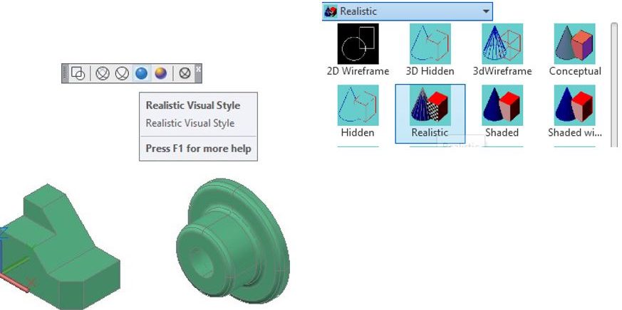
Click the Realistic visual style icon and note how when the current visual style is Realistic, the appearance of the model is the most basic realistic view of a shaded solid or surfaced model. (Figure Step 11)
Step 12
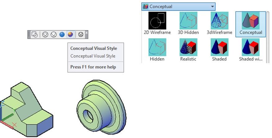
Click the Conceptual visual style icon and note how when the current visual style is Conceptual, the appearance of the solid model is more of an artistic look. (Figure Step 12)
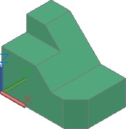
Step 13
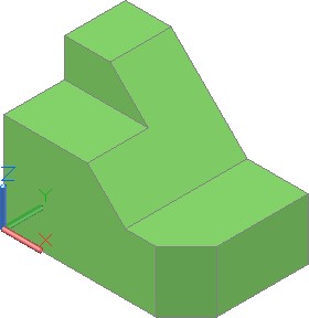
Delete the cylindrical solid model leaving only one solid model. Change the current visual style to Realistic and your model should now appear as shown in the figure. (Figure Step 13)
Step 14
If you are using Toolbar menus, enable the display of the Orbit toolbar. If you are using Ribbon menus, use the View-Orbit pull-down menu. Click the Constrained Orbit icon. (Figure Step 14A and 14B).
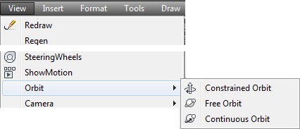
Figure Step 14A
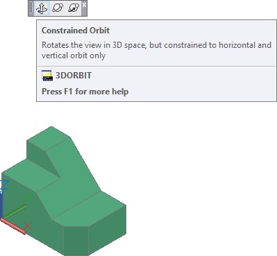
Figure Step 14B
Step 15
When constrained orbit command is active, it displays the icon as shown in the figure. (Figure Step 15)

Step 16
Orbit the model and note how this command affects the position of the model. Press Esc to exit the command.
Step 17
Click the Free Orbit icon and orbit the model. Note how this command affects the position of the model. Press Esc to exit.
Step 18
Click the Continuous Orbit icon and use it to orbit the model. Read the Author’s Comments. (Figure Step 18)
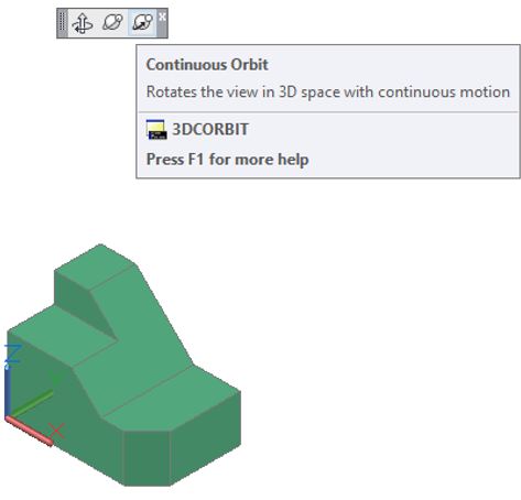
AUTHOR’S COMMENTS: The continuous 3D orbit feature is an interesting and fun feature in AutoCAD. After you enter this command, the Continuous 3D Orbit icon, Figure 10-2, will appear on the Graphic window. Hold down the mouse’s pick button, spin the model and release the button. The model will start to rotate continuously until you stop it by clicking in the Graphic window or by pressing the Esc key. The faster you spin it, the faster the model rotates.
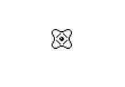
Continuous 3D Icon
Step 19
Set the current view to SE Isometric.
Step 20
Save and close the drawing.
MUST KNOW: Surface and solid models can be viewed in many visual styles. Models can be viewed as a wireframe, a hidden, or a solid. In a hidden style, the model will appear as it would in real life. It obstructs the lines and curves that are behind the visible surfaces. In the solid style, the model is shaded. A shaded model will be shaded with the same color as the model.
The VSCURRENT command controls which visual style is used to display the model. It will remain displayed in the that visual style until the current visual style is changed. Even if the drawing is closed and opened again, the visual style of the model remains as it was last set.
A model must be constructed as a surface or a solid to be viewed hidden or shaded. A wireframe model will only display in the 2D Wireframe or 3D Wireframe visual style. Constructing surface and solid models is taught in Modules 11 to 30.
AutoCAD System Variable: VPCONTROL
Enables or disables the display of the Viewport Controls menu.
Shortcut: none
WORK ALONG: Using the Viewport Controls Menu
Step 1
Open the drawing: AutoCAD 3D Workalong 10-1. (Figure Step 1)
Step 2
Enter the system variable VPCONTROL and set it to ON, as shown below.
Command: VPCONTROL
Enter new value for VPCONTROL <OFF>: ON
Command:
Step 3
Step 2 will enable the display of the Viewport Controls menu located in the top left corner of the Graphic window. (Figure Step 3A, 3B, and 3C)
Toolbar Menu
Ribbon Menu

Step 4
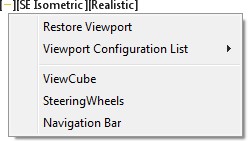
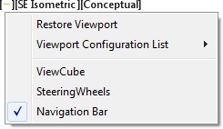
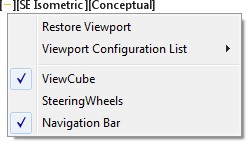
Click the small dash on the left side of the menu. This will pull down a list of menu items. Ensure that all items are disabled, as shown in the figure. (Figure Step 4)
Step 5
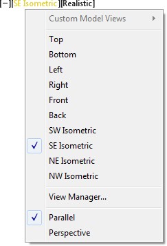
Click the View menu. It should read SE Isometric. This will pull down the list of the predefined views as shown in the figure. (Figure Step 5)
Step 6
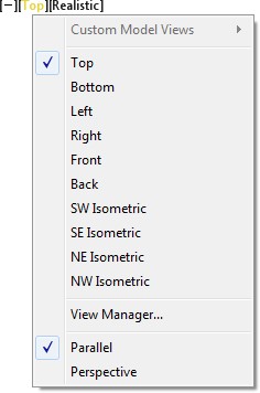
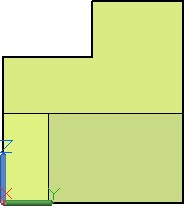
Enable Top to change the current view of the model to the Top. (Figure Step 6A and 6B)
Step 7
Pull down the View menu and set the current view to SE Isometric. (Figure Step 7A and 7B)


Step 8
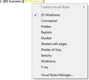
Click the Visual Style menu and in the pull down list, set the current visual style to 2D Wireframe. (Figure Step 8A and 8B)
Step 9
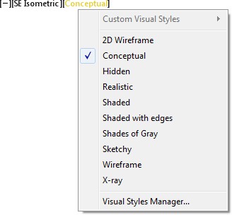
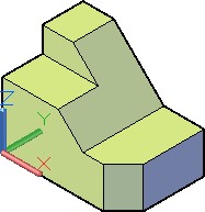
Click the Visual Style menu and in the pull down list, set the current visual style to Conceptual. (Figure Step 9A and 9B)
Step 10
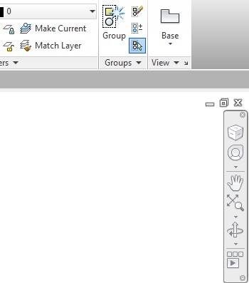
Click the small dash on the left side of the menu to pull down the menu. Enable Navigation Bar. The Navigation Bar will display on the right side of the Graphic window as shown in the figure. (Figure Step 10A and 10B)
Step 11
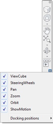
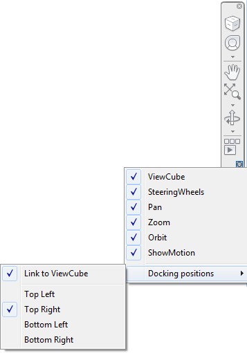
Click the small arrow located at bottom right corner of the Navigation Bar to pull down its menu. Ensure that all six item are enabled as shown in the figure. (Figure Step 11)
Step 12
Click the small arrow again located at the bottom of the Navigation Bar to pull down its menu. Click the Docking positions item to display the flyout menu. Ensure the enabled items match the figure. (Figure Step 12)
Step 13
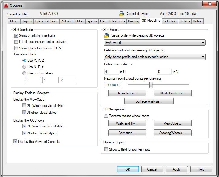
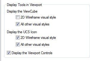
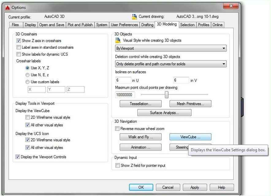
Open the Options dialogue box using the OPTIONS command. Enable the All other visual styles item under the Display the ViewCube, as shown in the figures. Click OK to close the dialogue box. (Figure Step 13A and 13B)
Step 14
Click the small dash on the left side of the menu to pull down the menu. Enable ViewCube. The ViewCube will display on the right side of the Graphic window, as shown in the figure. (Figure Step 14A and 14B)
Step 15
Save and close the drawing.
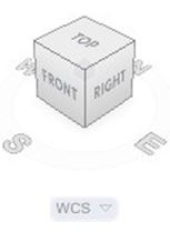
ViewCube is a valuable AutoCAD 3D tool that provides visual feedback of the current orientation of the model and a very quick and effective method of changing your viewpoint of the model. See Figure 10-3.
ViewCube can be used to restore and define the Home view of a model, switch between views of the model, projection modes and change its interactive behavior and appearance.
ViewCube
AutoCAD Command: NAVVCUBE
The NAVVCUBE command controls the visibility and display properties of the ViewCube tool.
Shortcut: none
WORK ALONG: Using ViewCube
Step 1
Open the drawing: AutoCAD 3D Workalong 10-1. (Figure Step 1)

Step 2
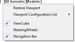
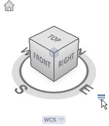
Click the small dash on the left side of the Viewport Controls menu. Ensure that ViewCube and Navigation Bar are enabled as shown in the figure. (Figure Step 2)
Step 3
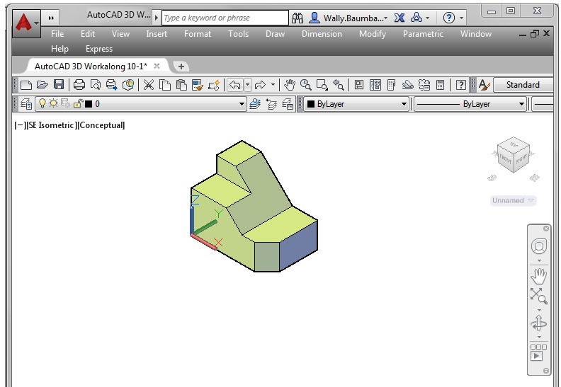
The Graphic window should appear similar to the figure. (Figure Step 3)
Step 4
Ensure that the current view is set to SE Isometric.
Step 5
Click the arrow icon located on the lower right side of ViewCube. (Figure Step 5)
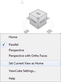
Step 6
In the pull-down menu, click Set Current View as Home. (Figure Step 6)
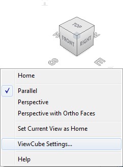
Step 7
Click the arrow again and click ViewCube Settings (Figure Step 7)
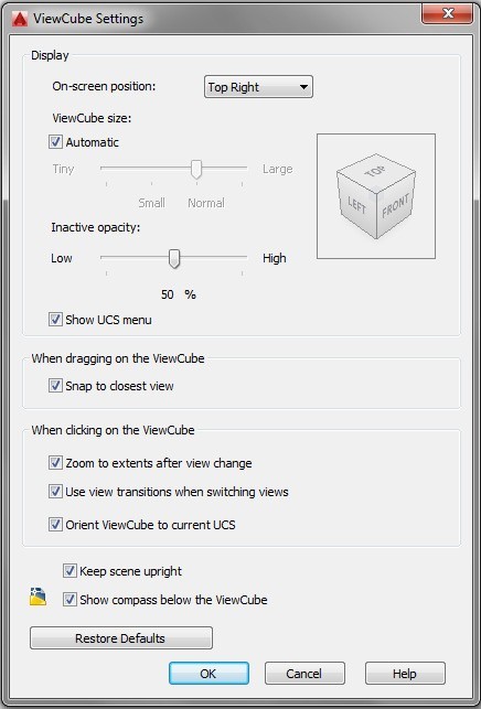
Step 8
Set the ViewCube Settings dialogue box as shown in the figure. (Figure Step 8)
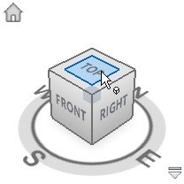
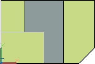
Step 9
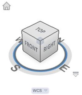
Move the cursor onto the top of ViewCube. When it turns blue, click it. The solid model’s current view will change to the Top view. (Figure Step 9A and 9B)
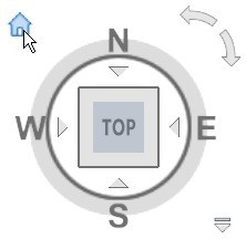
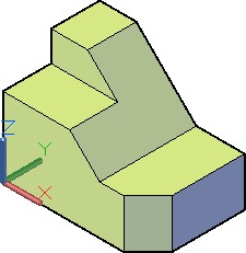
Step 10
Click the Home icon on ViewCube. It is the small house in the upper left corner. The model will now display the home view. For this model, it is SE Isometric. (Figure Step 10A and 10B)
Step 11
Using what you just learned, change the current view to Front. (Figure Step 11)
Step 12
Change the current view to Right. (Figure Step 12)
Step 13
Change the current view to the Home view. (Figure Step 13)

Step 14
Save and close the drawing.
Key Principles
Key Principles in Module 10
- Surface and solid models can be viewed in many visual Models can be viewed as a wireframe, a hidden, or a solid. A shaded model will be shaded with the same color as the model.
- The Viewport Controls menu is used to easily change the models orientation and visual style.
- ViewCube is a valuable AutoCAD 3D tool that provides visual feedback of the current orientation of the model and a very quick and effective method of changing your viewpoint of the model.
- ViewCube can be used to restore and define the Home view of a model, switch between views of the model, projection modes, and change its interactive behavior and appearance.