2.1: Module 7- Visualizing Multiview Drawings
- Page ID
- 19943

Module 7: Visualizing Multiview Drawings
Learning Outcomes
When you have completed this module, you will be able to:
- Draw isometric drawings on an isometric grid using multiview drawings as a reference.
- Construct 3D models in AutoCAD using multiview drawings.
Visualizing 3D Models
In the first six modules, all of the wireframe models that you constructed were referenced to a given 3D view of the model. Since most technical drawings used in the drafting and design world are 2D multiview drawings, 3D models must be able to be drawn using a multiview drawing as a reference to find the model’s shape and dimensions. To construct a 3D model, you must be able to mentally visualize the 3D model using a multiview drawing as a reference.
A good way for you to learn to visualize a 3D model from a 2D multiview drawing is to first draw the model as an isometric drawing. By doing this, it is easier to form a mental image from the multiview drawing. After practicing this for while, you will be able to visualize and construct 3D models without drawing the isometric first.
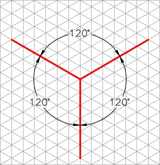
An Isometric Drawing
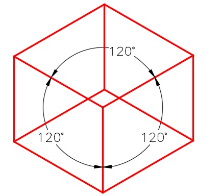
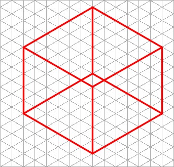
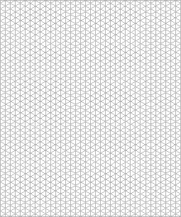
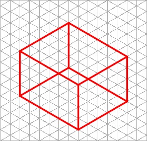
An isometric drawing is a 2-dimensional drawing that has the XYZ axis drawn at 120 degrees apart as shown in Figure 7-1. In this module, drawing the isometric on an isometric grid will be taught. An isometric grid has the grid lines drawn at 120 degrees as shown in Figure 7-2. Figure 7-3 shows a rectangular box drawn on the isometric grid.
A Rectangular Box Drawn on an Isometric Grid
WORK ALONG: Visualizing 3D Models
Step 1
Using the NEW command, start a new drawing using the template: 3D Layout English.
Step 2
Save and name the drawing: AutoCAD 3D Workalong 07-1.
Step 3
Set the UCS to World and the view to Top. Enter the UNITS command. In the Units dialogue box, set the Insertion Units to Inches. Using the INSERT command, insert the block: AutoCAD 3D Workalong 07-1 at the coordinates 0,0,0. Explode the block. The drawing should appear as shown in the figure. (Figure Step 3)
Step 4
Change the layer of the isometric grid from layer: 0 to layer: Grid.
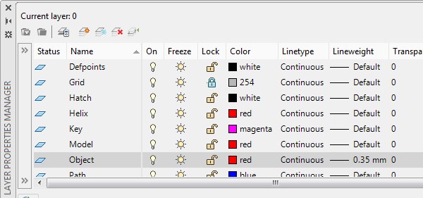
Step 5
Lock layer: Grid and set the lineweight of layer: Object to 0.35 mm. (Figure Step 5)
Step 6
Enable OSNAP and LWT. (Figure Step 6)

Step 7
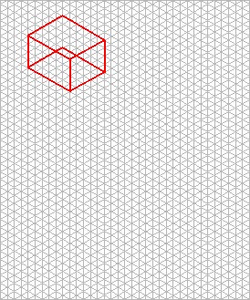
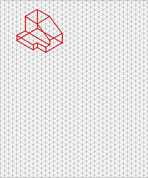
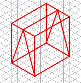
Figure Step 7A shows the multiview drawing of Object 7-1. Set layer: Object as the current layer and draw a box 6 grids long, 5 grids wide and 4 grids high. Where it is drawn is not that important but it should be located somewhere in the top left corner. Ensure that all lines are snapped to the grid intersections. Since layer: Grid is locked, the lines can be freely moved on layer: Object, as required. (Figure Step 7A, 7B, and 7C)
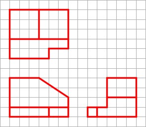
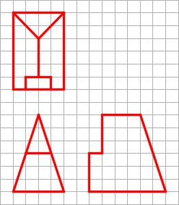
Multiview Drawing – Object 7-1
Step 8
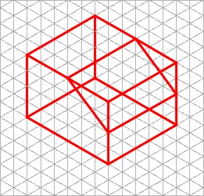
To draw the contour of the Front view, count the number of grids for the diagonal cut off. It is 3 grids on the X axis and 2 grids on the Z axis. Using those dimensions, draw the inclined lines on the front and rear view and add the lines to connect them. (Figure Step 8)
Step 9
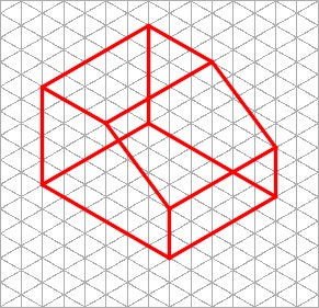
Trim and delete the lines to complete the contour of the front view. (Figure Step 9)
Step 10
Add the lines to cut out the contour of the Right Side view. (Figure Step 10)
Step 11
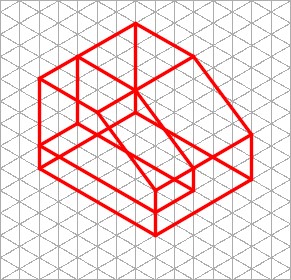
Trim and delete the necessary lines to complete the Right Side view contour and then add the lines to form the Top view contour. (Figure Step 11)
Step 12
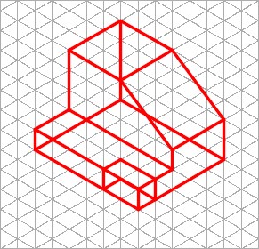
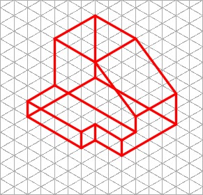
Trim and delete any unwanted lines to complete the isometric object: Object 7-1. The drawing should appear similar to figure. (Figure Step 12A and 12B)
Step 13
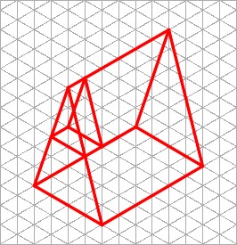
Using what was just taught, draw the isometric drawing of: Object 7-2. Draw it in the top right corner of the grid. (Figure Step 13)
Step 14
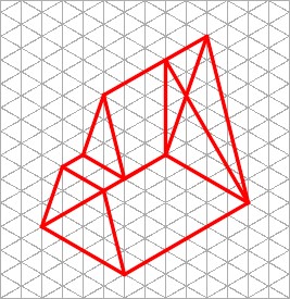
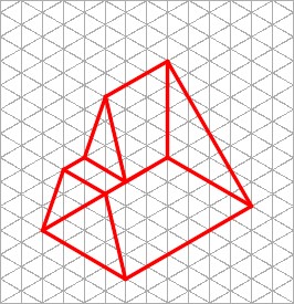
The figures show the necessary steps. Try to complete the isometric without looking at the figure. (Figure Step 14A, 14B, 14C, and 14D)
Step 15
Your drawing should now appear similar to the figure. (Figure Step 15)
Step 16
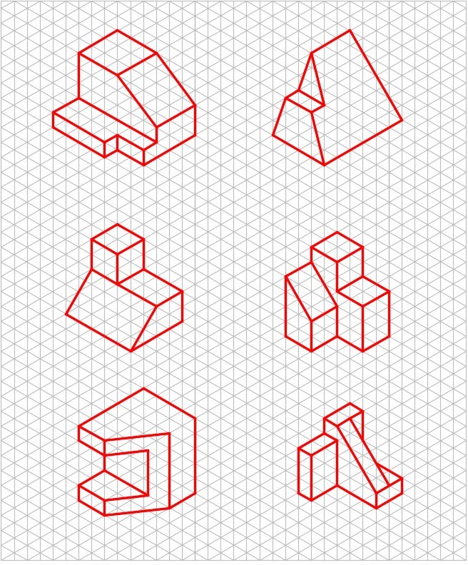
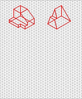
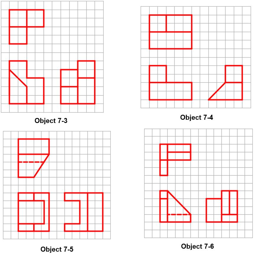
Using what was just taught, draw isometric drawings of the four objects: Object 7-3 to Object 7-6. For the answers, see Figure “Isometric drawing of Object 7-1 to Object 7-6” at the end of this chapter. Try to visualize the 3D model by looking at the multiview drawing and then draw the isometric. Do not look at the answers until you have done your best to complete the isometric drawing of each object. (Figure Step 16)
Step 17
Save and close the drawing.
Key Principles
Key Principles in Module 7
- An isometric drawing is a 2-dimensional drawing that has the XYZ axis drawn 120 degrees
- An isometric drawing is only used in the AutoCAD 3D book as a teaching They are mostly obsolete in the CAD design and drafting world.
Lab Exercise 7-1
Time allowed: 40 minutes.
| Drawing Name | Template | Units |
|---|---|---|
| AutoCAD 3D Lab 07-1 | 3D Layout English | Inches |
Step 1
Draw all construction objects on layer: Construction and all model objects on layer Model. When complete, freeze layer: Construction.
Step 2
Draw a wireframe model of the object. (Figure Step 2A, 2B, and 2C)
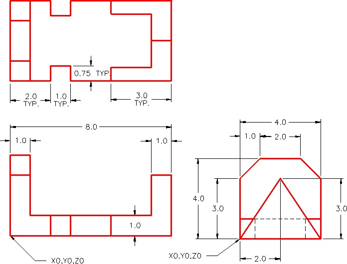
Dimensioned Multiview Drawing
Step 3
Start with the current view SE Isometric. If required, orbit it slightly with 3DFORBIT to help your line of sight.
Step 4
Enter the UNITS command. In the Units dialogue box, set the Insertion Units to Inches. Change the current UCS to World and check the model with the key.
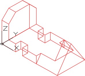
Complete Wireframe Model
Solid Model – SE Isometric View