
3.1: Module 12- Surface Modeling – Part 1
- Page ID
- 19949

Module 12: Surface Modeling – Part 1
Learning Outcomes
When you have completed this module, you will be able to:
- Describe surface faces and meshes and explain when and why they are used.
- Apply the 3DFACE command to create simple face surfaced models.
Surface Models
A surface model is a 3D model with all of its outer surfaces covered with a thin coating. Think of it as an empty box with a balloon skin. All the sides that define its shape are covered but it is hollow on the inside. Unlike a solid model, the volume, weight, and centre of gravity of a surface model cannot be calculated by AutoCAD. Solid modeling is taught in Modules 17 to 31.
There are many reasons why surface models are constructed rather than solid models. A surface model can be used to create objects that have complex curved shapes which are difficult to construct as a solid models. For industries such as the automobile, aircraft, and ship design, surfaces are used as a crucial part of their CAD design. For 3D mapping, surface meshes are used to define the 3D physical shape of the earth.
Surface Types
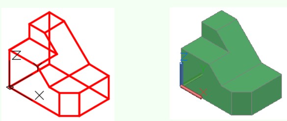
A surface can be either created with a face or a mesh or a combination of the two. A surface face is a good method to create simple surfaces while a surface mesh works for all surfaces including complex and curved surfaces. Figure 12-1 shows a model covered with a surface mesh. Faces and meshes can be combined, on the same model, when surfacing a model by creating some of the surfaces with faces and some with meshes. Once a model is surfaced, it can be shaded as shown in Figure 12-2.
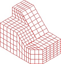
Model with Surface Mesh

Shaded Surfaced Model
USER TIP: Although a model can be created with surfaces alone, it is much easier to construct it as a wireframe model first. Draw the wireframe on layer Model and when it is complete, create the surfaces and then freeze layer Model.
AutoCAD Command: 3DFACE
The 3DFACE command is used to create a surface face bounded by a minimum of three and a maximum of four edges.
Shortcut: 3F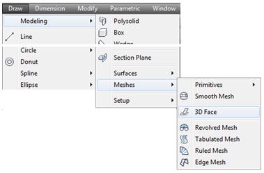
WORK ALONG: Inserting Surface Faces
Step 1
Using the NEW command, start a new drawing using template: 3D Layout English.
Step 2
Save and name the drawing: AutoCAD 3D Workalong 12-1.
Step 3
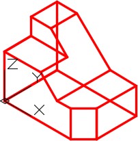
Set the current UCS to World. Enter the UNITS command and in the Units dialogue box, set the Insertion Units to Inches. Using the INSERT command, insert the block:
AutoCAD 3D Lab 01-2 at the coordinates 0,0,0. Explode the block and set the current view to SE Isometric. (Figure Step 3)
Step 4
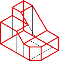
Change the layer of all wireframe lines to layer: Model. (Figure Step 4)
Step 5
On layer: Construction, draw the construction lines to help you insert the surfaces. Keep in mind that the maximum number of sides that a face can be bound by is 4. Draw the lines on all six sides. (Figure Step 5)
Step 6
Set layer: Surface Face as the current layer. Enter the 3DFACE command, as shown below, to place a surface face on the wireframe model. Ensure you snap to the endpoints of the wireframe lines. (Figure Step 6)
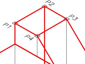
Command: 3DFACE
Specify first point or [Invisible]: (end) P1
Specify second point or [Invisible]: (end) P2
Specify third point or [Invisible] <exit>: (end) P3
Specify fourth point or [Invisible]: (end) P4
(The surface face is defined by snapping to endpoints of existing wireframe lines. Pick points moving around the surface. Do not crisscross.)
Command:
Step 7
Enter the 3DFACE command as shown below. In this command, insert the common edges on the same plane as invisible. The figure shows the two edges (marked with an I) that should be inserted as invisible. (Figure Step 7)
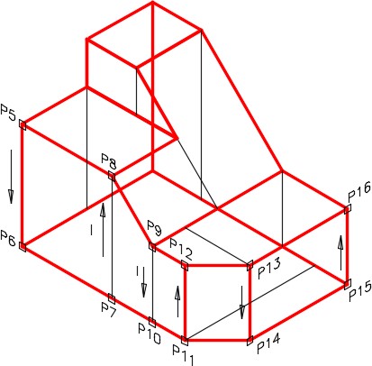
Command: 3DFACE
Specify first point or [Invisible]: (end) P5
Specify second point or [Invisible]: (end) P6
Specify third point or [Invisible] <create three-sided face>: I
(You want the last edge to be invisible.)
Specify third point or [Invisible] <exit>: (end) P7
Specify fourth point or [Invisible] <create three-sided face>: (end) P8
Specify third point or [Invisible] <create three-sided face>: I
(You want the last edge to be invisible.)
Specify third point or [Invisible] <exit>: (end) P9
Specify fourth point or [Invisible] <create three-sided face>: (end) P10
Specify fourth point or [Invisible] <create three-sided face>: (end) P11
Specify fourth point or [Invisible] <create three-sided face>: (end) P12
Specify fourth point or [Invisible] <create three-sided face>: (end) P13
Specify fourth point or [Invisible] <create three-sided face>: (end) P14
Specify fourth point or [Invisible] <create three-sided face>: (end) P15
Specify fourth point or [Invisible] <create three-sided face>: (end) P16
Specify third point or [Invisible] <exit>:
Command:
Step 8
To check the surfaces you just inserted, set the current visual style to Realistic as shown in the figure. (Figure Step 8)
Step 9
Change the current visual style to 3D Wireframe.
Step 10
Using the 3DFACE command, add faces to completely surface the model. Ensure that you apply faces on the back and bottom. Turn layers: Model and Construction off.
Step 11
Change the current visual style to Realistic. Using the 3DFORBIT command, ensure that the complete model is surfaced. (Figure Step 11A and 11B)

Step 12
Save and close the drawing.
Key Principles
Key Principles in Module 12
- A surface model is a 3D model with all of its outer surfaces covered with a A surface can be either created with a face or a mesh. A surface face is a good method to create simple surfaces while a surface mesh works for all surfaces including complex and curved surfaces.
- Faces and meshes can be combined when surfacing a model by creating some of the surfaces with faces and some with
- The 3DFACE command is used to create a surface face bounded by a minimum of three and a maximum of four The faces can be joined together with visible or invisible edges to make the faces appear as large as necessary.
Lab Exercise 12-1
Time allowed: 60 minutes.
| Drawing Name | Template | Units |
|---|---|---|
| AutoCAD 3D Lab 12-1 | 3D Layout English | Inches |
Step 1
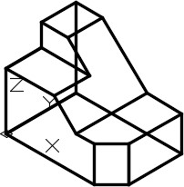
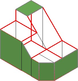
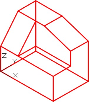
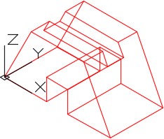
On layer: Model, draw a wireframe model of the object shown in the figures. (Figure Step 1A, 1B, and 1C)
Step 2
On layer: Surface Face, create surface faces on all surfaces including the back and bottom. Make all surface edges invisible.
Step 3
Freeze layers: Construction and Model.
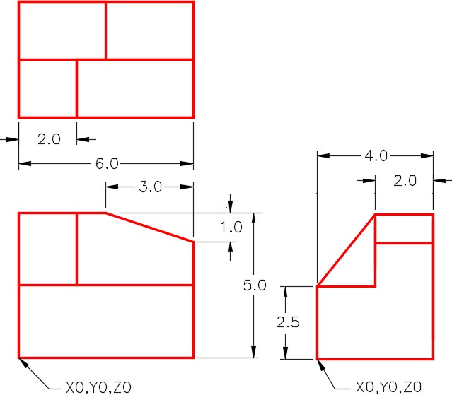
Dimensioned Multiview Drawing
Step 4
See the current visual style to Realistic. Using 3DFORBIT, check it for completeness.
Step 5
Set the Insertion Units, change the current UCS to World and check the model with the key.
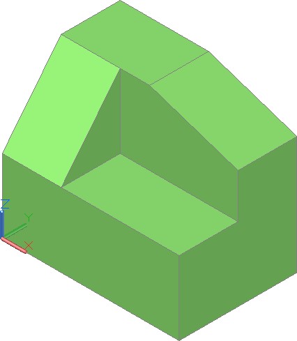
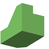
Shaded Model
Step 6
Save and close the drawing.
Lab Exercise 12-2
Time allowed: 40 minutes.
| Drawing Name | Template | Units |
|---|---|---|
| AutoCAD 3D Lab 12-2 | N/A | Millimeters |
Step 1
Open the drawing: AutoCAD 3D Lab 05-2.
Step 2
Using the SAVEAS command, save the drawing with the name: AutoCAD 3D Lab 12-2.
Step 3
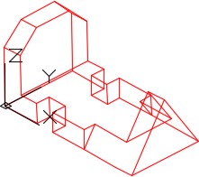
On layer: Surface 3, create surface faces on each side including the back and bottom. (Figure Step 3A and 3B)
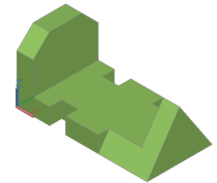
Wireframe Model
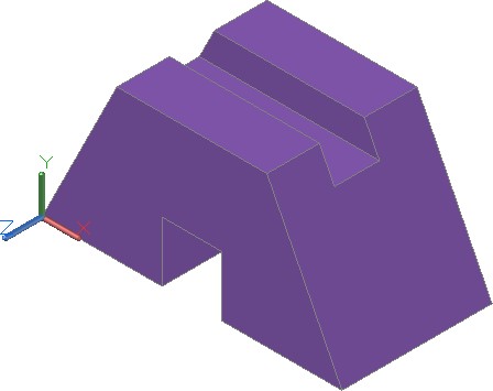
Surfaced Model – Shaded
Step 4
Freeze layers: Construction and Model.
Step 5
See the current visual style to Realistic. Using 3DFORBIT, check it for completeness.
Step 6
Save and close the drawing.
Lab Exercise 12-3
Time allowed: 40 minutes.
| Drawing Name | Template | Units |
|---|---|---|
| AutoCAD 3D Lab 12-3 | N/A | Inches |
Step 1
Open the drawing: AutoCAD 3D Lab 07-1.
Step 2
Using the SAVEAS command, save the drawing with the name: AutoCAD 3D Lab 12-3.
Step 3
On layer: Surface 2, create surface faces on each side including the back and bottom. Surface all of it with mesh surfaces. (Figure Step 3A and 3B)
Wireframe Model
Surfaced Model – Shaded
Step 4
When complete, freeze layers: Construction and Model.
Step 5
See the current visual style to Realistic. Using 3DFORBIT, check it for completeness.
Step 6
Save and close the drawing.