
5.5: Module 31 Competency Test No.6 Open Book
- Page ID
- 19974

Module 31 Competency Test No.6 Open Book
Learning Outcomes
When you have completed this module, you will be able to:
- Within a three hour time limit, complete a written exam and the lab exercises without the aid of a key.
The AutoCAD 3D book was written with competency based modules. What that means is that you have not completed each module until you have mastered it. The Competency Test module contains multiple choice questions and a comprehensive lab exercise to test your mastery of the set of modules that you completed. There are no answers or keys supplied in a Competency Test module since it is meant to be checked by your instructor. If there are any parts of this module that you have trouble completing, you should go back and reread the module or modules containing the information that you are having trouble with. If necessary, redo as many lab exercises required until you fully understand the material.
If you are completing this book:
- Without the aid of an instructor, complete the written test and the lab exercise.
- In a classroom with an instructor, the instructor will give instructions on what to do after this module has been completed.
Multiple Choice Questions
Select the BEST answer.
- Which three terms, of a 3D Solid, must the user be able to identify and select when using the SOLIDEDIT command?
- bodies, faces and solids
- faces, edges and regions
- bodies, edges and wireframes
- bodies, faces and edges
- edges, solids and regions
- What visual style must be current when the SOLVIEW command is used to create a 2D multiview(s) of a solid model?
- Realistic
- 2D Wireframe
- Hidden
- 3D Wireframe
- Any visual style
- Which one of the following item(s) must be set in the current drawing before the SOLDRAW and SOLPROF commands are used? Select the best answer.
- The Hidden linetype is loaded.
- The current visual style is 2D Wireframe.
- The current visual style is 3D Wireframe.
- A and B
- A and C
- What command is used to find out if two or more solids occupy the same 3D space?
- SAMESPACE
- SUBTRACT
- INTERFERE
- UNION
- EXPLODE
- Which SOLIDEDIT command option is used to divide two non-touching solid models back into individual solid models that have been joined with the UNION command?
- Separate
- Extrude
- Imprint
- Shell
- Check
- Which SOLIDEDIT command option is used to attach a 2D object onto an existing solid model?
- Imprint
- Extrude
- Separate
- Shell
- Check
- What two commands are used to a create 2D viewport(s), complete with hidden lines, of a solid model?
- SOLVIEW and MSPACE
- SOLVIEW and SOLDRAW
- MVIEW and SOLVIEW
- SOLPROF and MS
- MVIEW and PSPACE
- Which SOLIDEDIT command option is used to create a hollow cavity, with a specified wall thickness, in a solid model?
- Imprint
- Extrude
- Separate
- Shell
- Check
- What linetype must be loaded into the current drawing when using the SOLVIEW and SOLPROF commands?
- hidden
- center
- continuous
- dashed
- There is no specific linetype that has to be loaded.
- Which one of the following terms does the SOLIDEDIT command use when it prompts the user to select a solid model?
- Model
- Face
- Body
- Solid
- Edge
Lab Exercise 31-1
Time Allowed: 3 Hours
| Drawing Name | Template | Units |
|---|---|---|
| AutoCAD 3D Lab 31-1 | 3D Layout English | Inches |
Step 1
Start a new drawing using the template shown above. Save the drawing with the name: AutoCAD 3D Lab 31-1.
Step 2
Draw the polylines on layer: Pline.
Step 3
On layer: Solid 1, draw a solid model of the object shown in the figures. (Figure Step 3A and 3B)
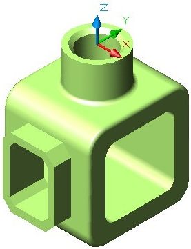
Completed Solid Model – SE Isometric View
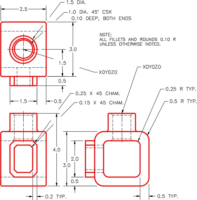
Dimensioned Multiview Drawing
Step 4
On layout: Module Layout C, use the SOLVIEW command to create the three viewports of the model.
Step 5
On layer: VPORT, using the MVIEW command to create viewport. Set the view, in the viewport, to SE Isometric and the visual style Realistic.
Step 6
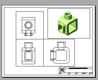
Set the scale of all four viewports to 1.25 and lock their display. (Figure Step 6)
Step 7
Use the SOLDRAW command to change the three multiviews views to 2D views.
Step 8
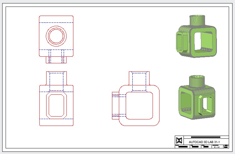
Set the current space to Paper and fill in the titleblock. (Figure Step 8)
Step 9
On layout: Module Layout D, using the SOLVIEW and SOLDRAW commands, create the three multiviews of the model.
Step 10
On layer: VPORT, using the MVIEW command, create two viewports. Set the visual style to Realistic and orbit them to match the figure the best you can by eye.
Step 11
Set the scale to 2:1 for the multiviews and 1.5:1 for the isometric views. Lock their display.
Step 12
Change the color of the layers so that the object lines are red and the hidden lines are blue. (Hint: See Module 30, WORKALONG: Creating 2D Drawings from a Solid Model, Step 16)
Step 13
Turn layer VPORT off.
Step 14
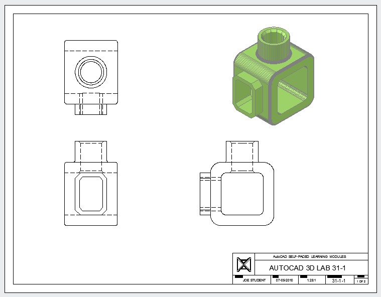
Set the current space to Paper and fill in the titleblock. (Figure Step 14)
Step 15
Save and close the drawing.