
6.1: Module 22 Sweeping
- Page ID
- 19975

Module 22 Sweeping
Learning Outcomes
When you have completed this module, you will be able to:
- Describe and apply the SWEEP command to create solid models by sweeping a closed profile along a path.
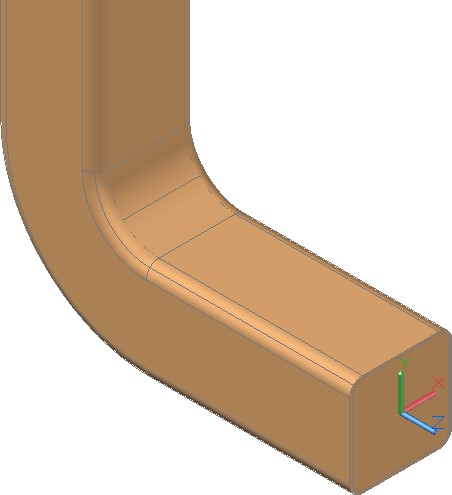
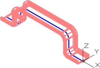
Sweeps
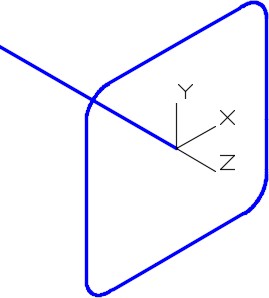
Sweeps are created by sweeping (moving) one or more profiles along a selected path. See Figure 22-1 and 22-2. The path can be an open or closed drawing object but must be one object. If the profile is a closed object, the sweep will create a solid. If the profile is an open object, the sweep will create a surface.
Sweeps are used to create models like pipes, tubbing, drain pipes, gasket grooves, and threads.
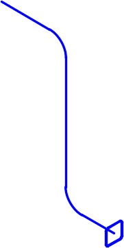
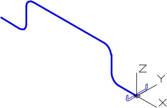
A Sweep Profile and Path
Objects that can be used for the path are 2D and 3D splines, 2D and 3D polylines, solids, surfaces and mesh edge sub-objects, helices, arcs, circles, ellipses, elliptical arcs and lines.
Objects that can be used for the profile are 2D and 3D splines, 2D polylines, 2D solids, 3D solid face subobjects, arcs, circles, ellipses, elliptical arcs, lines, regions, solids, surface mesh edge sub-objects and traces.
The system variable DELOBJ can be used to automatically delete or keep the original profile and path geometry used in the SWEEP command.
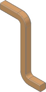
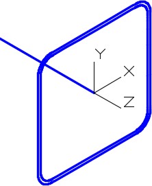
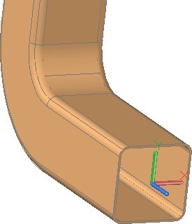
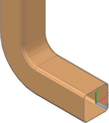
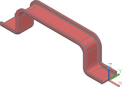
Completed Solid Model After the Sweep is Applied
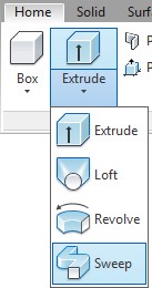
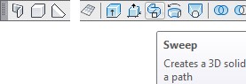
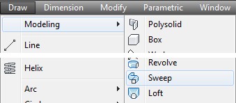
AutoCAD Command: SWEEP
The SWEEP command is used to create a 3D solid or surface model by sweeping a profile along a path.
Shortcut: none
WORK ALONG: Using the SWEEP Command – Part 1
Step 1
Using the NEW command, start a new drawing using template: 3D Layout English.
Step 2
Save and name the drawing: AutoCAD 3D Workalong 22-1. (Figure Step 2A, 2B, and 2C)
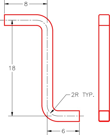
Dimensioned Multiview Drawing

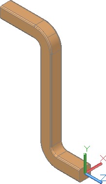
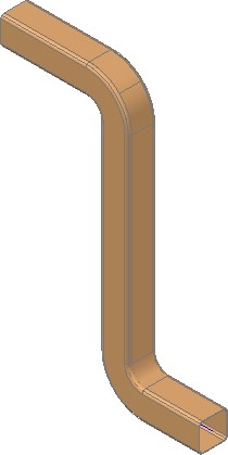
Completed 3D Solid
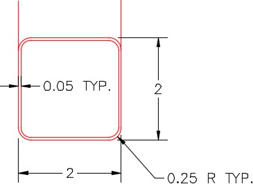
Dimensioned Detail of Opening
Step 3
Ensure that the DELOBJ system variable is set to 0.
Step 4
Change the visual style to 3D Wireframe.
Step 5
Set layer: Path as the current layer, the current view to SE Isometric, and the current UCS to Front.
Step 6
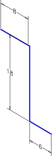
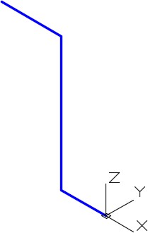
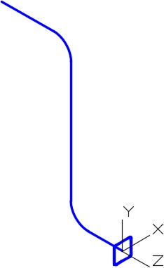
Using Figure Step 2A as a reference, enable Ortho mode, enter the PLINE command, as shown below, to draw a pline on the front UCS. Start the pline at 0,0,0. (Figure Step 6A and 6B)
Command: PLINE
Specify start point: 0,0,0
Current line-width is 0.0000
Specify next point or [Arc/Halfwidth/Length/Undo/Width]: <Ortho on> 6
Specify next point or [Arc/Close/Halfwidth/Length/Undo/Width]: 18
Specify next point or [Arc/Close/Halfwidth/Length/Undo/Width]: 8
Specify next point or [Arc/Close/Halfwidth/Length/Undo/Width]:
Command:
Step 7
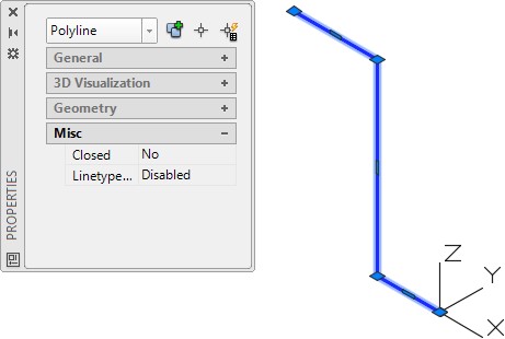
Using the Properties windows, check to ensure that the object is one polyline. (Figure Step 7)
Step 8
Using the FILLET command and the Polyline option, as shown below, fillet the corners with a radius of 2. (Figure Step 8)
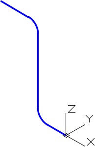
Command: FILLET
Current settings: Mode = TRIM, Radius = 0.0000
Select first object or [Undo/Polyline/Radius/Trim/Multiple]: R
Specify fillet radius <0.0000>: 2
Select first object or [Undo/Polyline/Radius/Trim/Multiple]: P
Select 2D polyline:
(Select the polyline.)
2 lines were filleted
Command:
Step 9
Set layer: Profile as the current layer and the current UCS to Right.
Step 10
Using the Figure Step 2C as a reference, draw a closed pline with its centre at the end of the path. The pline is 2 inches square. (Figure Step 10)
Step 11
Using what you learned earlier in the workalong, fillet the four corners of the pline with a radius of 0.25. (Figure Step 11)
Step 12
Using what you learned earlier, use the Properties windows and insure that object is a closed polyline.
Step 13
Offset the pline, towards the inside, at a distance of 0.05 inches. (Figure Step 13A and 13B)
Step 14
Set layer: Solid 4 as the current layer and the current visual style to Realistic.
Step 15
Use the SWEEP command, as shown below, to sweep both profiles along the path in one command. (Figure Step 15A and 15B)
Command: SWEEP
Current wire frame density: ISOLINES=4, Closed profiles creation mode = Solid
Select objects to sweep or [MOde]: 1 found
(Select one profile.)
Select objects to sweep or [MOde]: 1 found, 2 total
(Select the other profile.)
Select objects to sweep or [Mode]:
(Press Enter)
Select sweep path or [Alignment/Base point/Scale/Twist]:
(Select the path.)
Command:
Step 15
Turn layers: Path and Profile off.
Step 16
Using what you learned earlier in the book, use the SUBTRACT command to subtract the inner solid from the outer solid. (Figure Step 16A, 16B, and 16C)
Step 17
Save and close the drawing.
WORK ALONG: Using the SWEEP Command – Part 2
Step 1
Using the NEW command, start a new drawing using template: 3D Layout Metric.
Step 2
Save and name the drawing: AutoCAD 3D Workalong 22-2. (Figure Step 2)
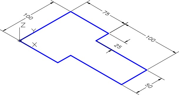
Dimensioned Drawing
Step 3
Set the current view to SE Isometric, the current UCS to World, the layer: Path as the current layer, and the current visual style to 2D Wireframe.
Step 4
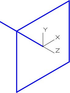
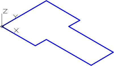
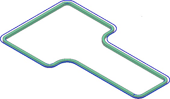
Using Figure Step 2 as a reference, draw a closed pline as shown in the figure. (Figure Step 4)
Step 6
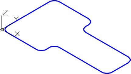
Using what you learned in the first workalong, fillet all of the corners, in one step, with a radius of 10. (Figure Step 6)
Step 7
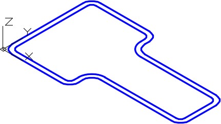
Offset the closed pline 5 mm towards the inside. (Figure Step 7)
Step 8
Set the system variable ISOLINES to 24.
Step 9
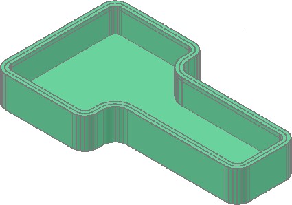
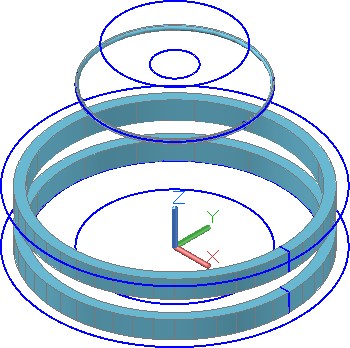
Set layer: Solid 1 as the current layer. Extrude the outer pline 25 mm in the negative Z. (Figure Step 9)
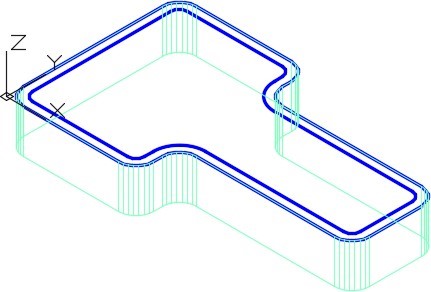
Step 10
Freeze layer: Solid Off. Change the layer of the extruded outer solid that you created in Step 9 to layer: Solid Off.
Step 11
Extrude the inner pline 20 mm in the negative Z. (Figure Step 11)
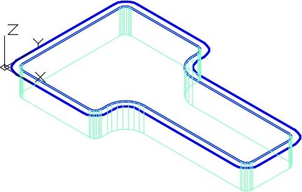
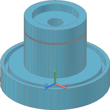
Step 12
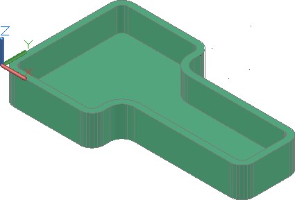
Change the layer of the first solid from layer: Solid Off to layer: Solid 1. Turn layer: Path off. Your drawing should match the figure. (Figure Step 12)
Step 13
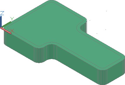
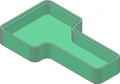
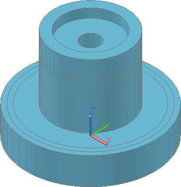
Change the visual style to Realistic. (Figure Step 13)
Step 14
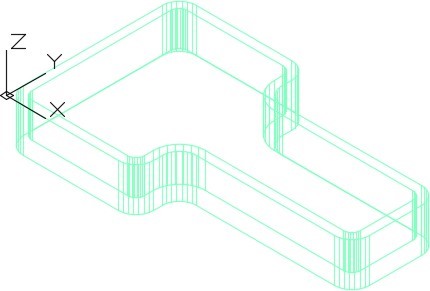
Using the SUBTRACT command, subtract the inner solid from the outer solid. (Figure Step 14)
Step 15
Change the layer of the solid on layer: Solid 1 to layer: Solid Off. Turn layer: Path on and set layer: Profile as the current layer. Set the visual style to 2D wireframe. (Figure Step 15)

Step 16
Change the current UCS to Right.
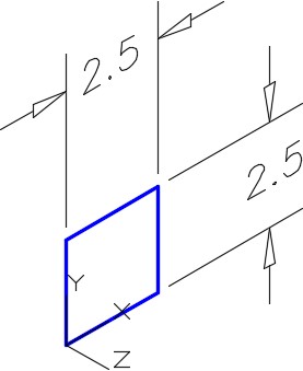
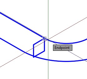
Step 17
Draw a closed pline 2.5 x 2.5 inches. Start it by snapping to endpoint of the inner pline. (Figure Step 17A, 17B, and 17C)
Step 18
Set layer: Solid 1 as the current layer.
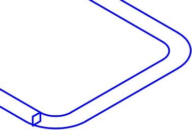
Step 19
Using the SWEEP command, sweep the 2.5 inch closed pline using the inner pline as the path. (Figure Step 19)
Step 20
Change the layer of the solid on layer: Solid Off to layer: Solid 1. Turn layers: Path and Profile off and change the visual style to Realistic. (Figure Step 20)
Step 21
Using the SUBTRACT command, subtract the solid that was created using the SWEEP command from the original solid. (Figure Step 21)
Step 22
Save and close the drawing.
Key Principles
Key Principles in Module 22
- Sweeps are created by sweeping (moving) one or more profiles along a selected path. The path can be an open or closed object but must be one object. If the profile is a closed object, the sweep will create a solid. If the profile is an open object, the sweep will create a surface.
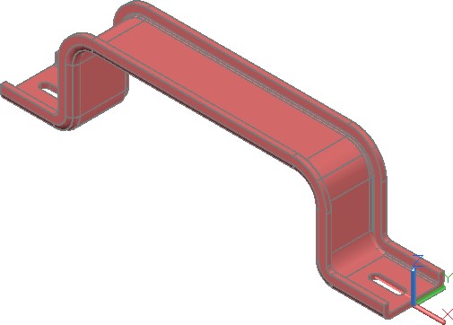
Lab Exercise 22-1
Time allowed: 60 minutes.
| Drawing Name | Template | Units |
|---|---|---|
| AutoCAD 3D Lab 22-1 | 3D Layout English | Inches |
Step 1
On layer: Profile, draw the profile as a closed pline and on layer: Path, draw the path as a single pline. (Figure Step 1A and 1B)
Step 2
On layer: Solid 6, create the solid using the SWEEP command.
Step 3
Create the slots by first creating one and mirror it to create the opposite slot. Subtract them to complete the object.
Step 4
Save and close the drawing.
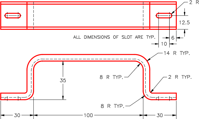
Dimensioned Multiview Drawing
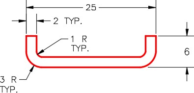
Detail of Right Side View
Lab Exercise 22-2
Time allowed: 60 minutes.
| Drawing Name | Template | Units |
|---|---|---|
| AutoCAD 3D Lab 22-2 | 3D Layout English | Inches |
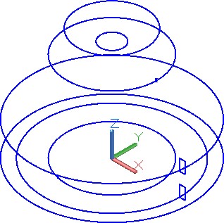
Step 1
On layer: Path, draw the paths as a circles, and on layer: Profile, draw the closed plines. (Figure Step 1A and 1B)
Step 2
On layer: Solid 3, create the original solid.
Step 3
On layer: Solid 3, create the solids that are to be subtracted using the SWEEP command.
Step 4
Subtract the sweep solids from the original solid.
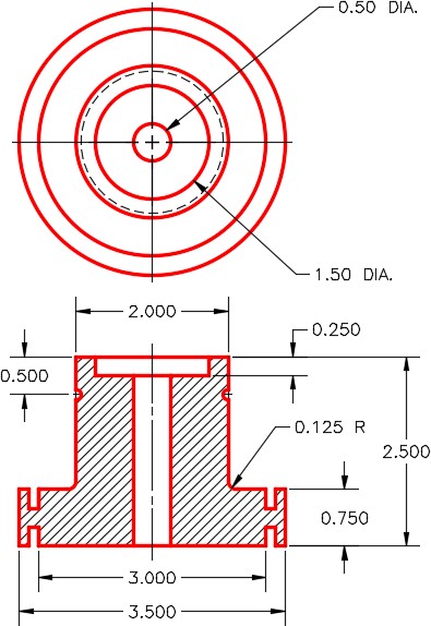
Dimensioned Multiview Drawing
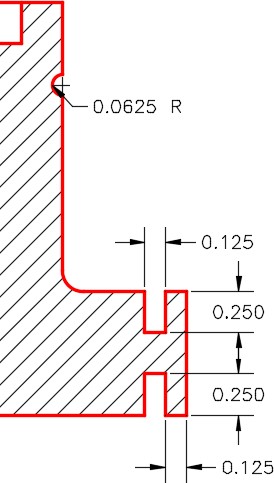
Dimensioned Detail
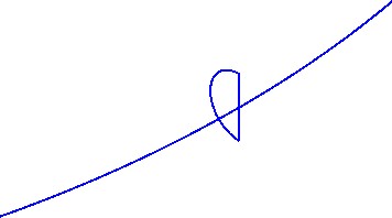
The arc profile must be created with an arc and line and then converted into a closed pline
Step 5
Save and close the drawing.