
3.2: Module 13 Arcs
- Page ID
- 19877

13
Module 13 Arcs
Wally Baumback
Learning Outcomes
When you have completed this module, you will be able to:
- Describe the geometry of an arc and how arcs are drawn in Inventor.
- Describe how to snap to midpoints of lines.
- Apply the CENTER POINT ARC command to draw arcs in 2D sketches.
Drawing Arcs
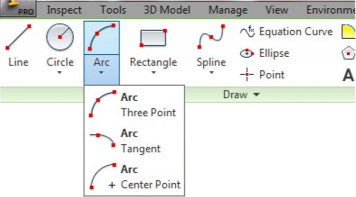
There are three commands available to draw arcs in Inventor. In this module, drawing arcs using the CENTER POINT ARC command will be taught. Similar to the CIRCLE command, the CENTER POINT ARC command also requires you to select the centre point and the radius. Drawing arcs additionally require you to locate the start point and end point or the arc. Arcs can be constructed clockwise or counterclockwise.
Geometry Lesson: Arcs
An ARC is defined as an open curve in which all points are the same distance from its centre point. Study the drawings in Figure 13-1 and 13-2.for a description of the geometry of an arc.
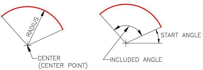
Geometry of an Arc – Part 1
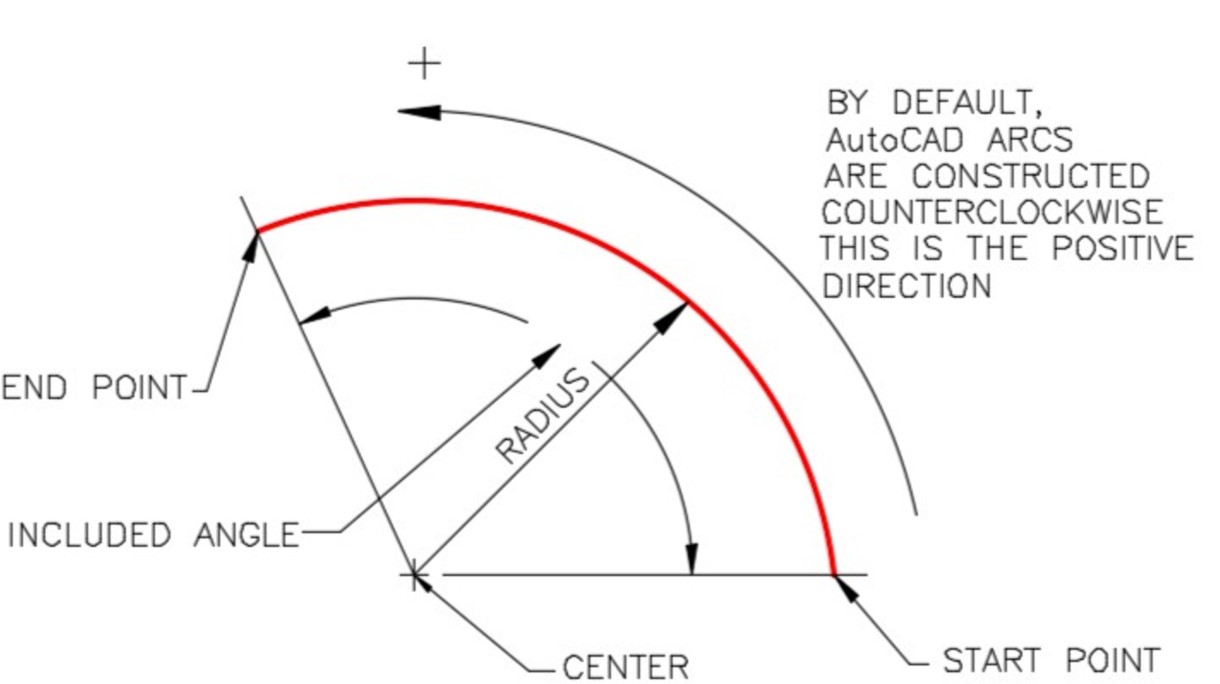
Geometry of an Arc – Part 2
Inventor Command: CENTER POINT ARC
The CENTER POINT ARC command is used to draw an arc by entering the location of its centre point, radius, start point and end point.
Shortcut: A
WORK ALONG: Drawing Models with Arcs
Step1
Check the default project and if necessary, set it to Inventor Course.
Step 2
Enter the NEW command to start a new part file using the template: Metric-Modules Part (mm).ipt.
Step 3
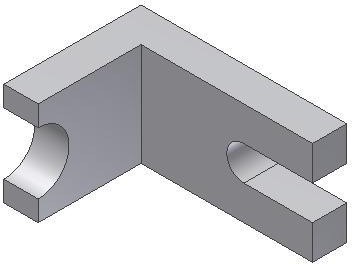
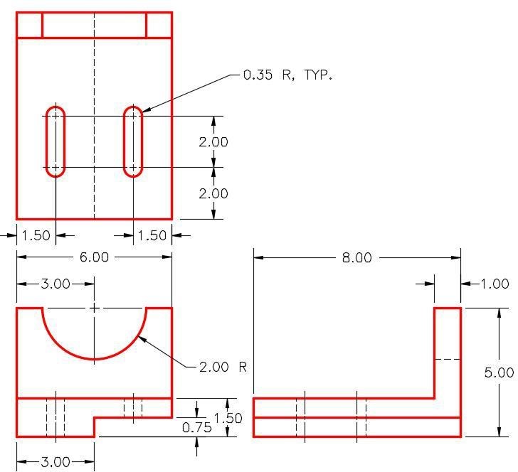
Save the file with the name: Inventor Workalong 13-1. (Figure Step 3A and 3B)
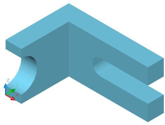
3D Model – Home View [Click to see image full size]
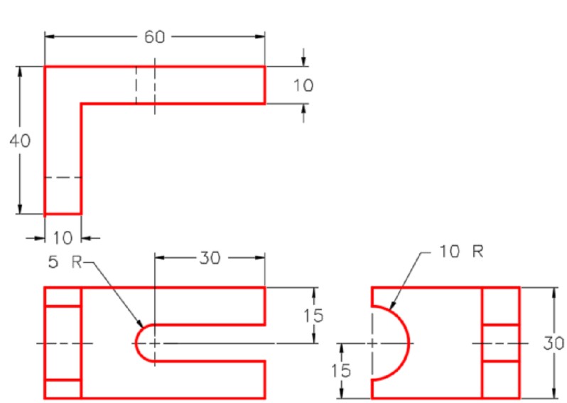
Dimensioned Multiview Drawing [Click to see image full size]
Step 4
Edit Sketch1. Project the Center Point onto the sketch.
Step 5
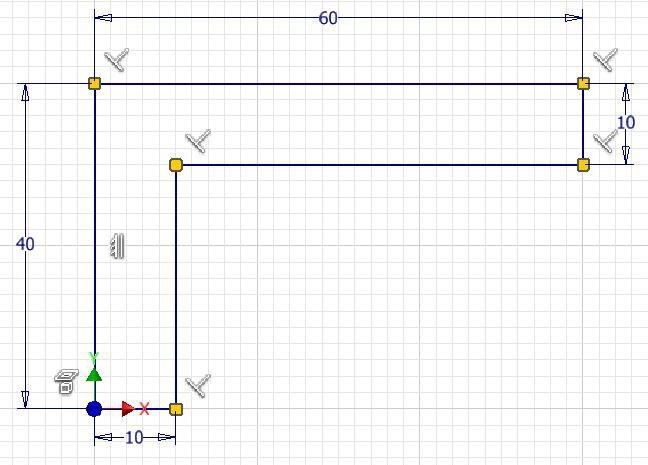
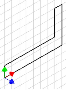
Draw a sketch of the Top view of the model. Apply all of the geometrical and dimensional constraints to fully constrain it. (Figure Step 5)
Step 6
Extrude the sketch in the positive Z direction. (Figure Step 6)
Step 7
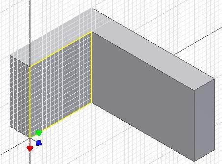
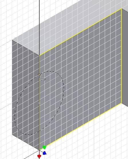
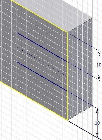
Start a new sketch on the right side as shown in the figure. (Figure Step 7)
Step 8
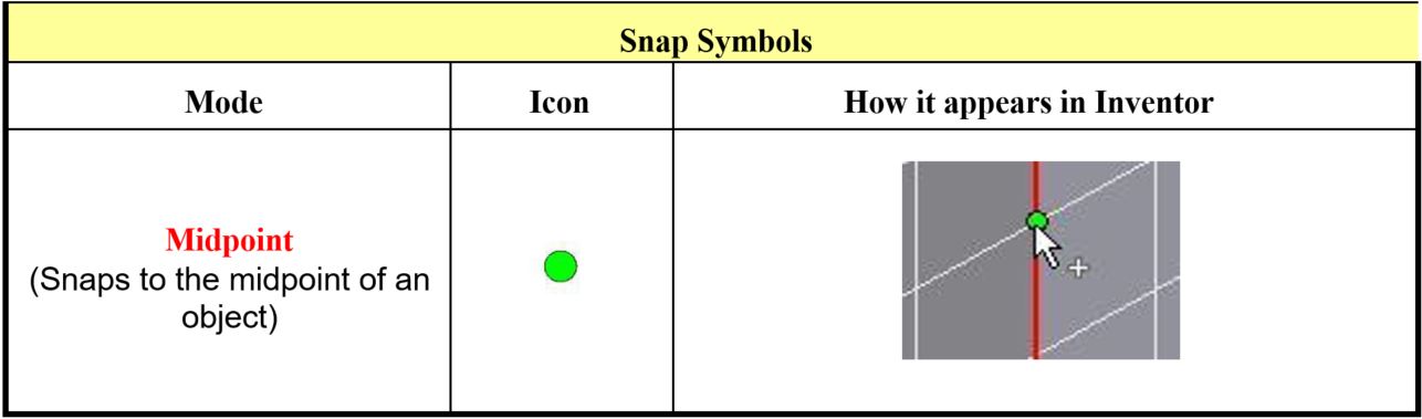
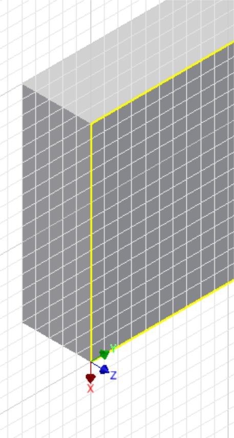
Enter the CENTER POINT ARC command and when prompted for the centre point, right click the mouse. In the Right-click menu, select Midpoint. (Figure Step 8)
Step 9
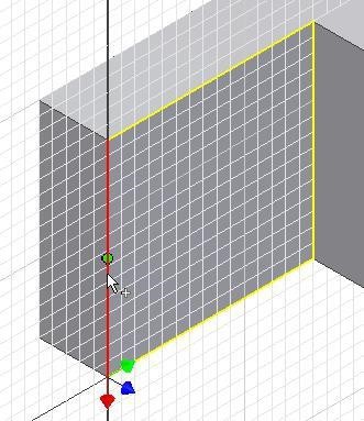
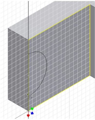
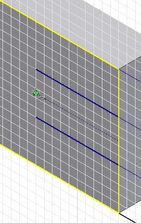
Move the cursor onto the vertical edge. When the green snap icon appears, click the left mouse button. (Figure Step 9)
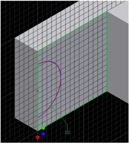
Step 10
Move the cursor approximately 10 mm along the edge and when the Snap onto icon displays, click the mouse. (Figure Step 10)
Step 11
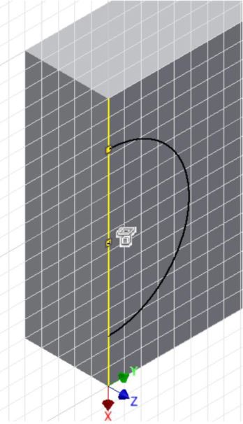
Move the cursor to the other side of the centre and when the Snap onto icon displays, click the mouse. (Figure Step 11)
Step 12
Press F8 to display the constraint icons. (Figure Step 12)
Step 13
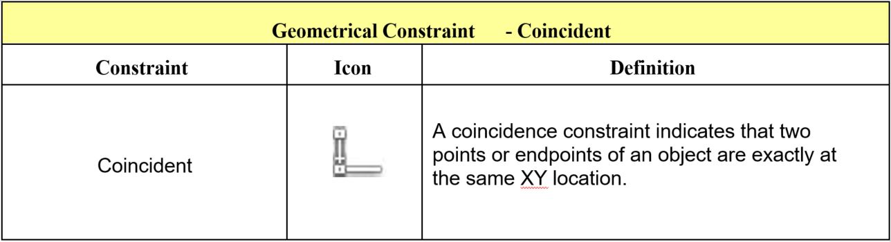
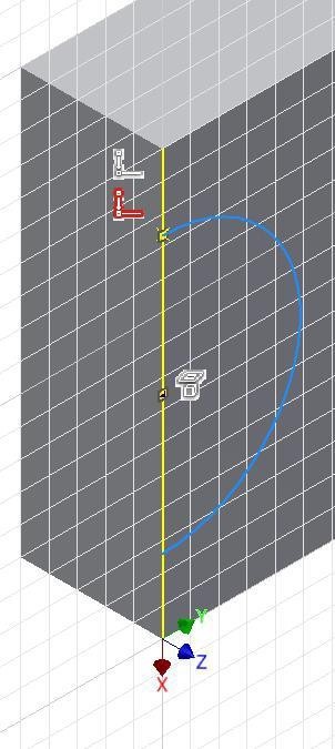
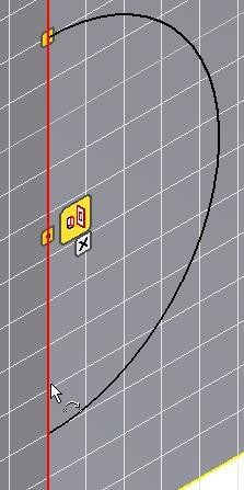
Move the cursor onto the Coincident icon and note the display of two coincident icons. (Figure Step 13)
Step 14
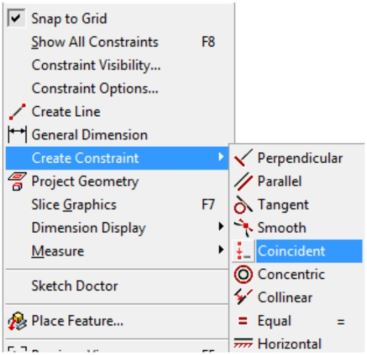
In the Graphic window, right click the mouse. In the Right-click menu, click Create Constraint and then Coincident. (Figure Step 14)
Step 15
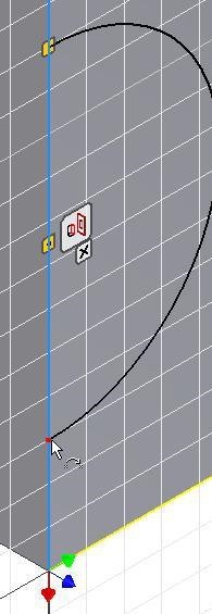
Select the edge for the first point. (Figure Step 15)
Step 16
For the second point, move the cursor onto the endpoint of the arc. When a small red point will displays, click the mouse. (Figure Step 16)
Step 17
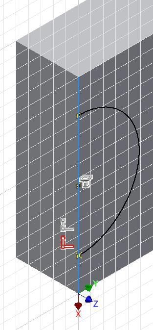
Press F8. Locate the cursor onto the Coincident icon and note the display of two coincident icons. (Figure Step 17)
Step 18
The arc should now display purple indicating it is fully constrained. (Figure Step 18)
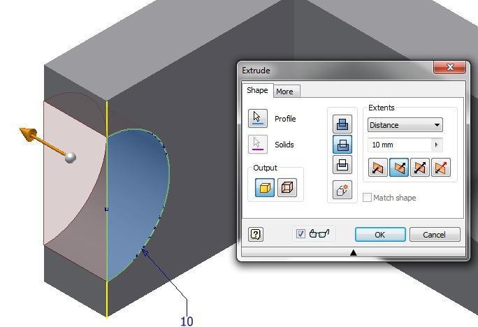
Step 19
Finish the sketch and extrude the arc by using the Cut option. (Figure Step 19)
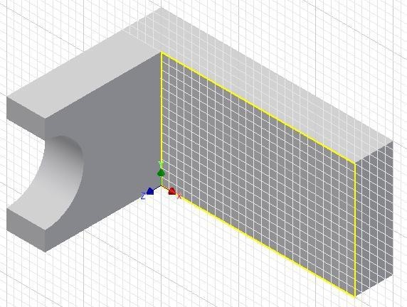
Step 20
Start a new sketch on the front side. (Figure Step 20)
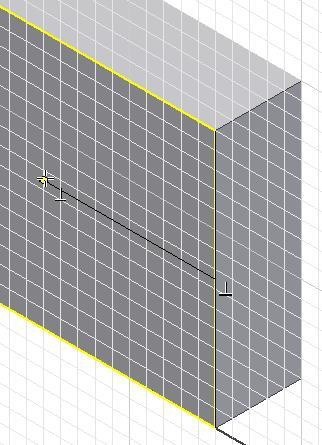
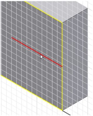
Step 21
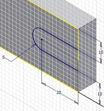
Draw a line perpendicular from the midpoint of the edge. (Figure Step 21)
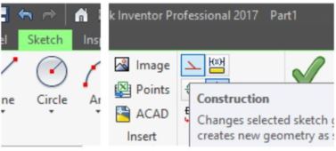
Step 22
Change the line to a construction line by selecting the line and then click the Construction icon. (Figure Step 22A, 22B, and 22C)
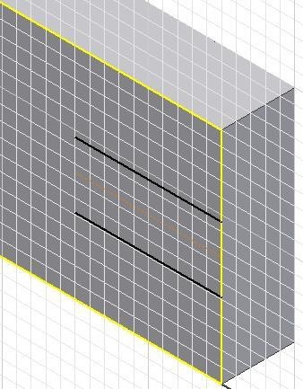
Step 23
Offset the construction line on each side. (Figure Step 23)
Step 24
Insert two dimensions. (Figure Step 24)
Step 25
Draw an arc locating the centre at the end of the construction line. (Figure Step 25)
Step 26
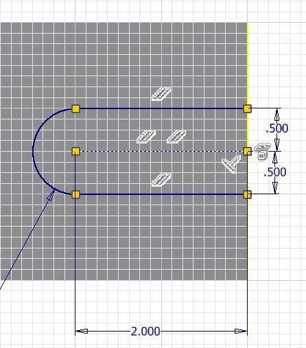
Insert the required dimensions to constrain the sketch. (Figure Step 26)
Step 27
Enable the display of the constraint icons. (Figure Step 27)

Step 28
Use what you learned in Step 14 to 17, create the additional Coincident constraints to fully constrain the sketch. (Figure Step 28)
Step 29
Extrude the sketch to complete the model. (Figure Step 29)
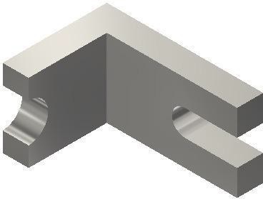
Step 30
Change the colour to: Titanium – Polished. (Figure Step 30).
Step 31
Save and close the file.
Key Principles
Key Principles in Module 13
- There are three commands available to draw arcs in Inventor. Similar to the CIRCLE command, the CENTER POINT ARC command also requires you to select the location of the centre point and the radius. Drawing arcs additionally requires you to locate the start point and end point or the arc. Arcs can be constructed clockwise or counterclockwise.
- When drawing arcs, do your best to tie the centre point, the start point, and the end point to existing geometry. This will decrease the number of dimensions that are required to constrain the arc.
Lab Exercise 13-1
Time allowed: 45 minutes.
| Part Name | Project | Units | Template | Color | Material |
| Inventor Lab Lab 13-1 | Inventor Course | Inches | English-Modules Part (in).ipt | Chrome – Polished | N/A |
Step 1
Project the Center Point onto the Base sketch.
Step 2
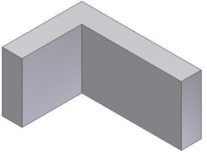
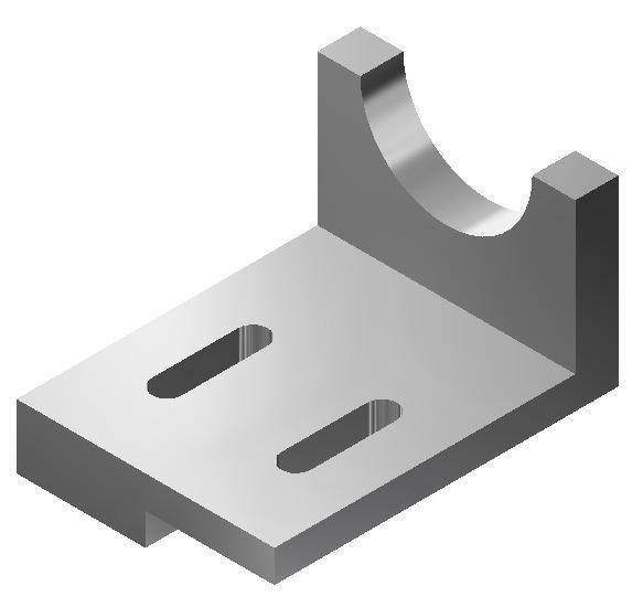
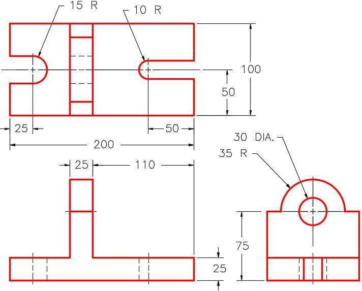
Note the location of X0Y0Z0. Draw the necessary sketches and extrude them to produced the solid model shown below. Apply all of the necessary geometrical and dimensional constraints to fully constrain all sketches. (Figure Step 2A and 2B)
Dimensioned Multiview Drawing [Click to see image full size]
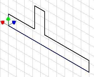
Suggested Base Sketch
– Right Side – YZ Plane
Step 3
Apply the colour shown above. (Figure Step 3)
Lab Exercise 13-2
Time allowed: 45 minutes.
| Part Name | Project | Units | Template | Color | Material |
| Inventor Lab Lab 13-2 | Inventor Course | Millimeters | Metric-Modules Part (mm).ipt | Copper – Satin | N/A |
Step 1
Project the Center Point onto the Base sketch.
Step 2
Note the location of X0Y0Z0. Draw the necessary sketches and extrude them to produced the solid model shown below. Apply all of the necessary geometrical and dimensional constraints to fully constrain all sketches. (Figure Step 2A and 2B)
Dimensioned Multiview Drawing [Click to see image full size]
Suggested Base Sketch –
Front – XZ Plane
Step 3
Apply the colour shown above. (Figure Step 3)
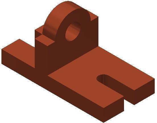
Completed Solid Model –
Home View