
3.4: Module 15 Fillet and Chamfer Features
- Page ID
- 19880

15
Module 15 Fillet and Chamfer Features
Wally Baumback
Learning Outcomes
When you have completed this module, you will be able to:
- 1 Describe fillet and chamfer features.
- Apply the FILLET and CHAMFER commands to create fillets and chamfers on solid models.
Fillets
A fillet is a tangent arc. A fillet is simply an arc which is tangent at both ends. It can be tangent to two lines, a line and an arc, or two arcs. Technically, it is a fillet when material is added to the object model and a round is when material is removed from the object. See Figure 15-1 and 15-2. Most CAD systems, including Inventor, use the term fillet for both.
There are two basic methods of inserting fillets in Inventor. In this module, inserting the fillets after the solid model is created will be taught. They are called features. In the Inventor Advanced book, drawing fillets on the 2D sketch will be taught. It is always better to insert the fillets as features since that makes them much easier to edit after the solid model is created.
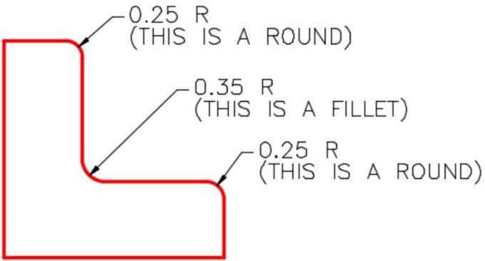
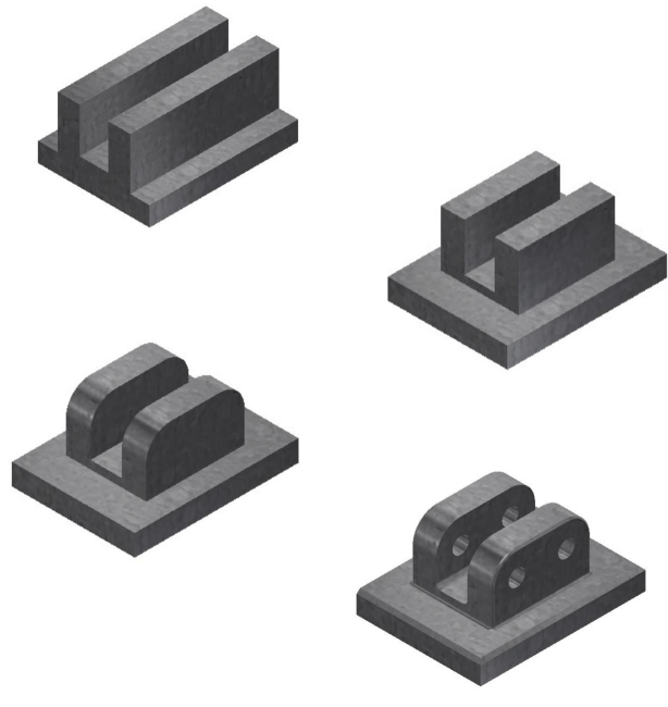
Fillets Dimensioned in 2D
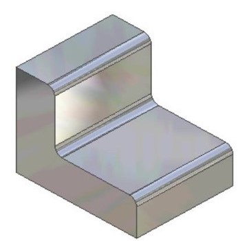
How Fillets Appear on the
Solid Model
Geometry Lesson Tangency – Part 1
A point of tangency is the theoretical point where a line joins an arc or where two arcs join each other making a smooth transition. A line tangent to a circle passes the circle and touches it on only one point on the circle. The point where they touch is called the point of tangency. See Figure 15-3.
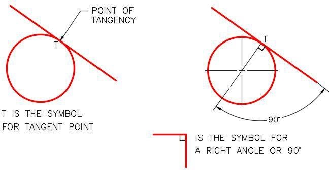
Tangency – Part 1
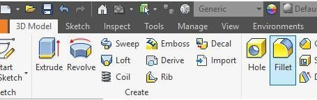
Inventor Command: FILLET
The FILLET command is used to insert a fillet feature on a solid model.
Shortcut: F
WORK ALONG: Creating Models With Fillet Features
Step 1
Check the default project and if necessary, set it to Inventor Course.
Step 2
Enter the NEW command to start a new part file using the template: English-Modules Part (in).ipt.
Step 3
Save the file with the name: Inventor Workalong 15-1. (Figure Step 3A and 3B)
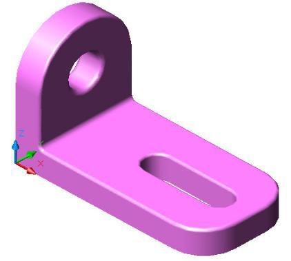
3D Model
Step 4
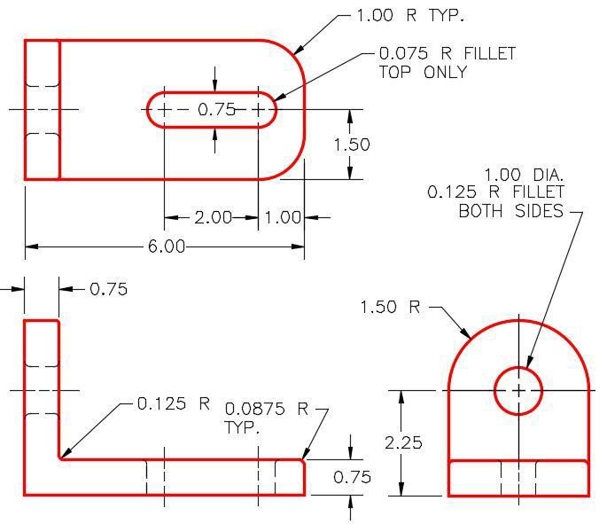
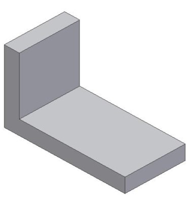
Draw the Base sketch on the Front view. Ensure that it is fully constrained. Extrude the sketch to create the Base model. (Figure Step 4A and 4B)

Step 5
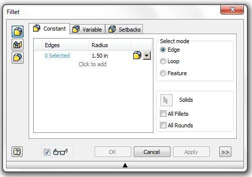
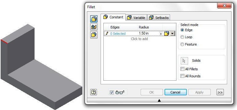
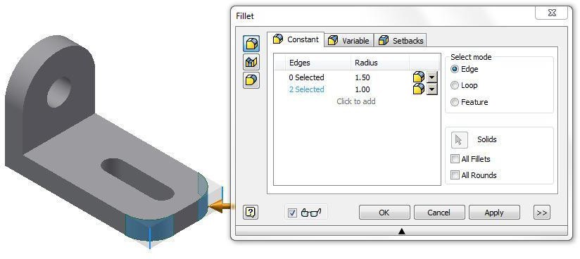
Enter the FILLET command and in the Fillet dialogue box, click the radius to edit it. Change the radius to 1.50. (Figure Step 5)
Step 6
Click the Pencil icon to change to the Arrow icon. When the Plus icon appears beside the cursor, select the top left corner of the model. (Figure Step 6A and 6B)
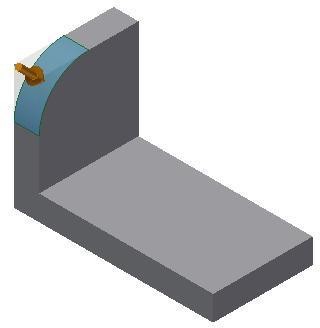
 Step 7
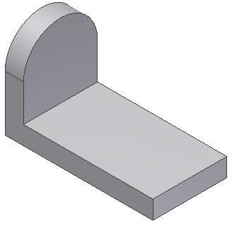
Insert the same fillet on the opposite side of the model. (Figure Step 7)
Step 8
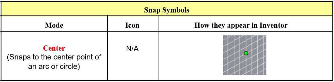
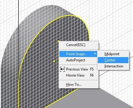
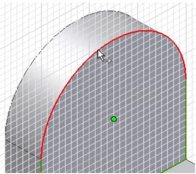
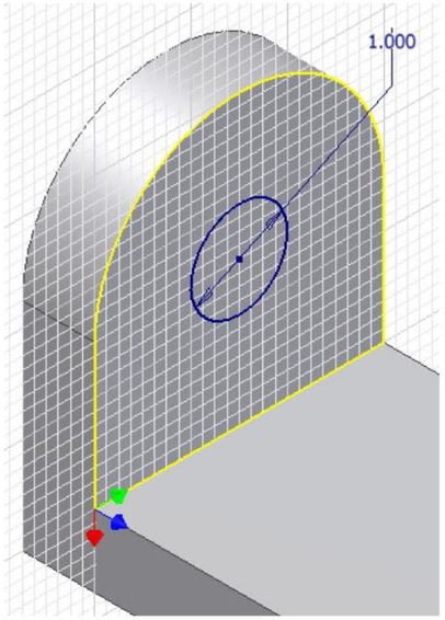
Start a new sketch and enter the CENTER POINT CIRCLE command. Right click the mouse. In the Right-click menu, select Center. Select the arc and draw a 1 inch Diam circle. Dimension and extrude it.(Figure Step 8A, 8B, 8C, and 8D)
Step 9
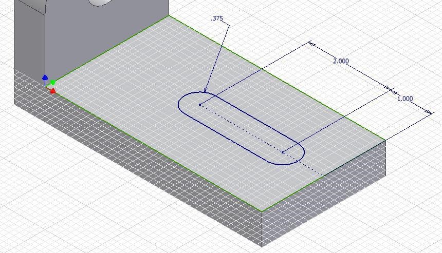
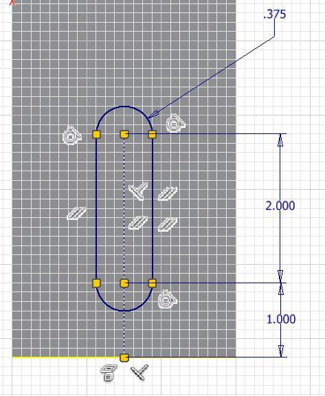
Start a new sketch. On it, draw and dimension the slot and extrude it. (Figure Step 9A and 9B)
Step 10
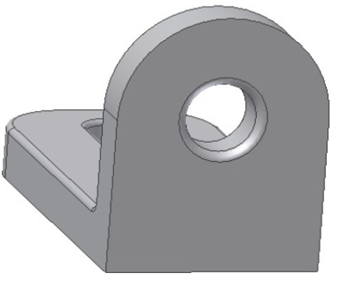
Using what you just learned, insert the 1 inch radius fillets. (Figure Step 10)
Step 11
Insert the fillets as shown on the figures. Ensure that you set the correct radius for each fillet. (Figure Step 11A and 11B)
Step 12
Enter the FILLET command and in the Fillet dialogue box, set the Radius to 0.0875. Set the Select mode to Loop and select the edge as shown in the figure. (Figure Step 12)
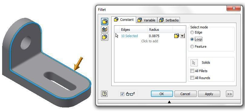
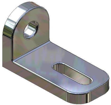
Step 13
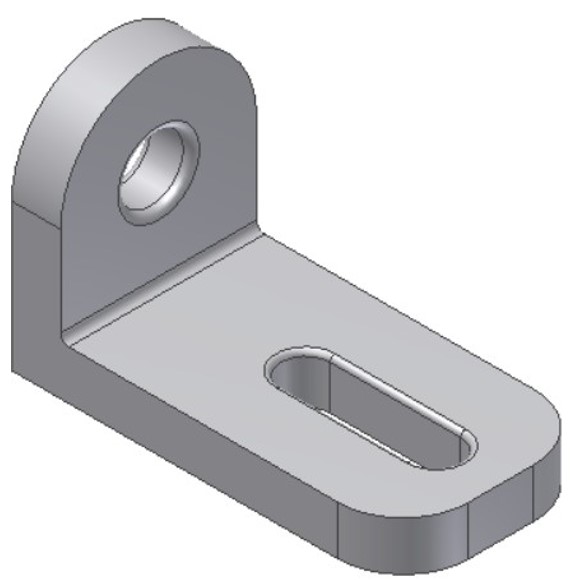
To complete the model, change the colour to: Chrome – Polished Black. (Figure Step 13)
Step 14
Save and close the file.
USER TIP: Inventor allows two methods of inserting fillets and chamfers. The first method is to create the solid model using extrude or revolution just as you have being doing to this point in the course and then insert the fillets on the solid model.The second method is drawing the fillets in the 2D sketch and they will be created when the sketch is extruded or revolved. The first method is the BEST method and should be used whenever possible. One reason that it is the best method is it allows you to decide the order of filleting. This is especially important where two or more fillets meet or intersect on the model. This is the method you will be using in this module.
Chamfers
A chamferis similar to a fillet except instead of an arc being inserted, it inserts an inclined line. See Figure 15-4. Figure 15-5 shows a multiview drawing with the chamfers dimensioned. There are two basic methods of inserting chamfers in Inventor, the same as fillets. In this module, you will learn how to insert them as features after the solid model is created as shown in Figure 15-6.
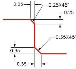
Chamfers
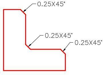
Chamfers in a Multiview Drawing
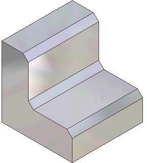
Chamfers on the Solid Model
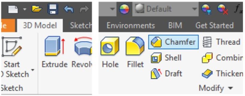
Inventor Command: CHAMFER
The CHAMFER command is used to create a chamfer feature on a solid model.
Shortcut: CTRL+ Shift+K
WORK ALONG: Creating Models with Chamfer Features
Step 1
Open the file: Inventor Lab 13-1.ipt that you created in Module 13.
Step 2
Using the SAVEAS command, save the file with the name: Inventor Workalong 15-2. (Figure Step 2A and 2B)
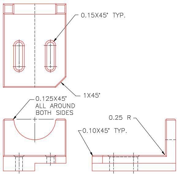
Dimensioned Multiview Drawing
Step 3
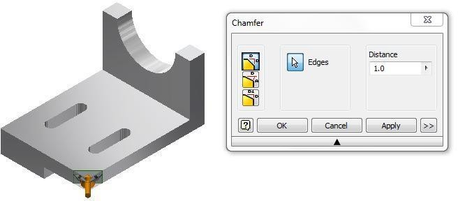
Enter the CHAMFER command. In the Chamfer dialogue box, ensure that the equal side icon and Edges icon are enabled. Set the distance to 1.0. Select the bottom right corner of the model. (Figure Step 3)
Step 4
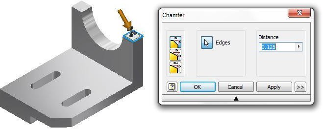
Set the distance to 0.125 and insert the chamfer on the around the top as shown in the figure. (Figure Step 4)
Step 5
Using what you just learned, insert the fillet and chamfers on the model as shown in the figure. (Figure Step 5)
Step 6
Insert the 0.10 chamfers around the outside as shown in the figure. (Figure Step 6)

Step 7
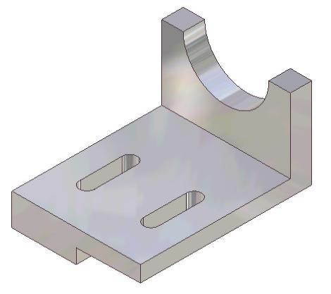
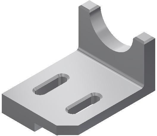
The completed model should appear as shown in the figure. (Figure Step 7)
Step 8
Save and close the file.
USER TIP: Many commands can be used while you are activity using another command. The ORBIT command is one of them. To increase your drawing speed, you can preform an operation on one side of a model and then, while you are still in the command, press F4 and rotate the model. Then preform the operation on another side. This would have worked well for Step 11 as you could have placed the fillet on the other side of the hole in the same FILLET command.Key Principles
Key Principles in Module 15
- A fillet is a tangent arc. A fillet is simply an arc which is tangent at both ends. It can be tangent to two lines, a line and an arc or two arcs.
- A chamfer is similar to a fillet except instead of an arc being inserted, it creates an inclined line.
- There are two basic methods of inserting fillets in Inventor. In this module, inserting the fillets after the solid model is created will be taught. They are called features. In the Inventor Advanced Modules, drawing fillets on the 2D sketch will be taught. It is always better to insert the fillets as features since that makes them much easier to draw and edit after the solid model is created.
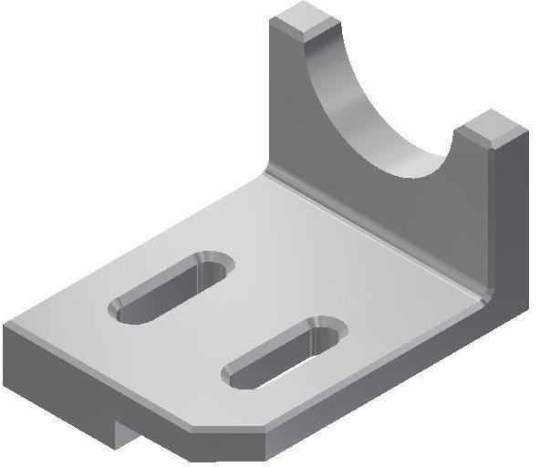
Lab Exercise 15-1
Time allowed: 60 minutes.
| Part Name | Project | Units | Template | Color | Material |
| Inventor Lab Lab 15-1 | Inventor Course | mm | Metric-Modules Part (mm).ipt | Steel – Galvanized | N/A |
Step 1
Project the Center Point onto the Base plane.
Step 2
Note the location of X0Y0Z0. Draw the necessary sketches and extrude them to produced the solid model shown in the figures. Apply all of the necessary geometrical and dimensional constraints to fully constrain all sketches. (Figure Step 2A, 2B, and 2C)
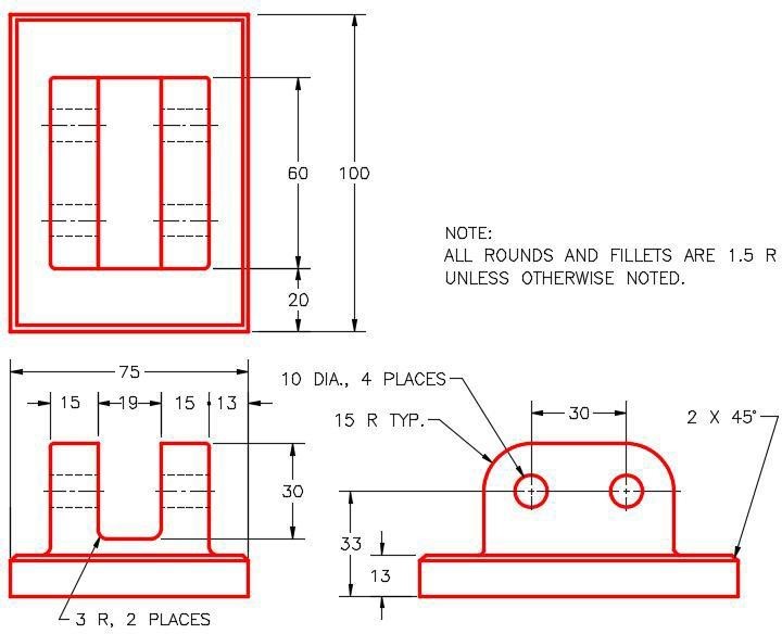
Dimensioned Multiview Drawing
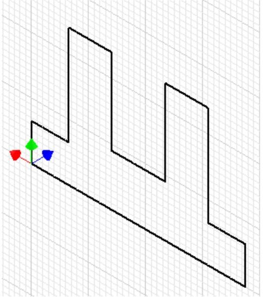
Suggested Base Sketch –
Front – XZ Plane
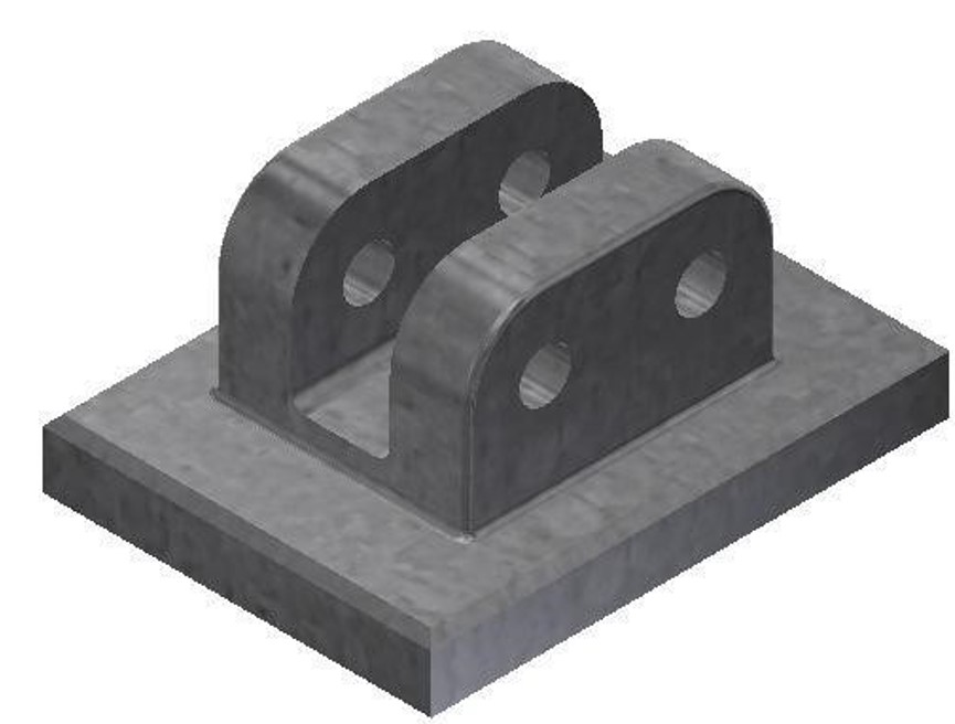
3D Model – Home View
Step 3
Insert the fillets and chamfers as features after the model is constructed.
Step 4
Apply the colour shown above.
Lab Exercise 15-2
Time allowed: 30 minutes.
| Part Name | Project | Units | Template | Color | Material |
| Inventor Lab Lab 15-2 | Inventor Course | Inches | N/A | Aluminum – Polished | N/A |
Step 1
Open the file: Inventor Lab 14-2.ipt that you created in Module 14.
Step 2
Using the SAVEAS command, save it with the name: Inventor Lab 15-2.
Step 3
Add the fillets and chamfers as features as shown in the figures. (Figure Step 3A, 3B, and 3C)
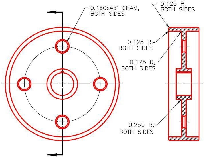
Dimensioned Multiview Drawing

Solid Model –
Home View
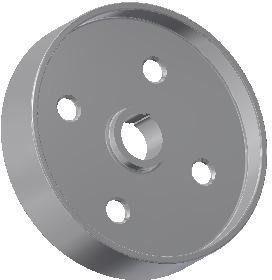
Solid Model –
Rotated View