
3.5: Module 16 Competency Test No.3 Open Book
- Page ID
- 19881

16
Module 16 Competency Test No.3 Open Book
Wally Baumback
Learning Outcomes
When you have completed this module, you will be able to:
- Within a two hour time limit, complete a written exam and a lab exercises.
Competency Tests
The Inventor book was written with competency based modules. What that means is that you have not completed each module until you have mastered it. The Competency Test module contains multiple choice questions and a comprehensive lab exercise to test your mastery of the set of modules that you completed. There are no answers or keys supplied in a Competency Test module since it is meant to be checked by your instructor. If there are any parts of this module that you have trouble completing, you should go back and reread the module or modules containing the information that you are having trouble with. If necessary, redo as many lab exercises required until you fully understand the material.
If you are Completing this book:
- Without the aid of an instructor, complete the written test and the lab exercise.
- In a classroom with an instructor, the instructor will give instructions on what to do after you have completed this module.
Multiple Choice Questions
Select the BEST answer.
- Which on of the following statements is true?
- Construction objects are drawn with the command CONSTRUCTION.
- Construction objects will not be used when the sketch is converted into a 3D feature.
- Construction objects cannot be used to constrain the sketch.
- Construction objects cannot be used as dimensional constraints.
- Construction objects will be used when the sketch is converted into a 3D feature.
- When is it best to place fillets and chamfers on a solid model?
- The last thing you do to complete the solid.
- The first thing after the base sketch it is revolved.
- Before the base model is created.
- When the sketches are being created.
- The first thing after the base sketch is extruded.
- Which snap mode is used to snap to the location where two object cross?
- On
- Midpoint
- Intersection
- Point
- Center
- Which one of the following function keys, when pressed, enables the display of the constraint icons?
- F2
- F4
- F6
- F8
- F10
- What two commands are used to create a solid model?
- REVOLVE AND OFFSET
- EXTRUDE and REVOLVE
- EXTRUDE and FILLET
- PROJECT and SOLID
- EXTRUDE and MODEL
- Which key or keys, when pressed while you are selecting objects, will allow you to select more then one object in the selection set?
- Only TAB
- Either ALT or SHIFT
- Either CTRL or ALT
- Either TAB or CTRL
- Either CTRL or SHIFT.
- What does the REVOLVE command do when it finds a centerline in the base sketch it is revolving?
- It automatically uses the centerline as the axis of revolution.
- It prompts you to select the axis of revolution.
- It extrudes the base sketch using it as the centre.
- It ignores the centerline.
- It allows you to select another axis as the axis of revolution.
- Which snap mode is used when you want to snap to the centre of a line?
- On
- Midpoint
- Intersection
- Point
- Center
- Which geometrical constraint is used to make 4 circles all the same diameter when only one of them is dimensioned?
- Tangent
- Concentric
- Coincident
- Center
- Equal
- What one of the following is used to change the properties of a selected object from a drawing object to a construction object?
- Construction menu
- Construction icon
- Construction line
- Construction circle
- Construction object
Lab Exercise 16-1
Time allowed: 60 minutes.
| Part Name | Project | Units | Template | Color | Material |
| Inventor Lab Lab 16-1 | Inventor Course | Inches | English-Modules Part (in).ipt | Chrome – Polished Blue | N/A |
Step 1
Note the location of X0Y0Z0. Draw the necessary sketches and revolve or extrude them to produce the 3D model. (Figure Step 1)
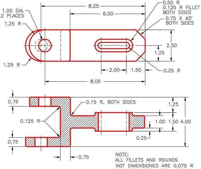
Dimensioned Multiview Drawing [Click to see image full size]
Step 2
Draw the base sketch on the Front view. (Figure Step 2)
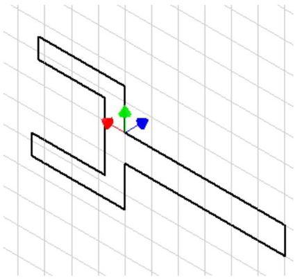
Suggested Base Sketch –
Front View (XZ Plane)
Step 3
Apply all of the necessary geometrical and dimensional constraints to fully constrain all sketches. Ensure that all objects, on all sketches, display purple on a black background.
Step 4
Create the fillets and chamfers after the solid model is totally constructed.
Step 5
Apply the colour shown. (Figure Step 5A, 5B, and 5C)
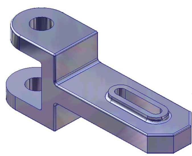
Solid Model – Home View
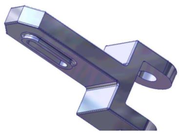
Solid Model – Rotated View
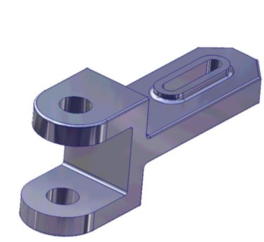
Solid Model – Rotated View
Lab Exercise 16-2
Time allowed: 60 minutes.
| Part Name | Project | Units | Template | Color | Material |
| Inventor Lab Lab 16-2 | Inventor Course | Millimeters | Metric-Modules Part (mm).ipt | Silicon Nitrite – Polished | N/A |
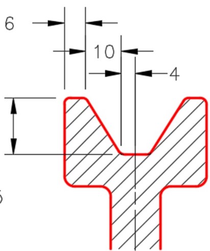
Step 1
Note the location of X0Y0Z0. Draw the base sketch on the Right Side view and revolve it to create the base model. (Figure Step 1A, 1B, 1C, and 1D)
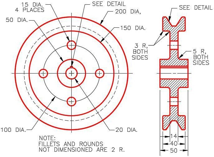
Dimensioned Multiview Drawing [Click to see image full size]
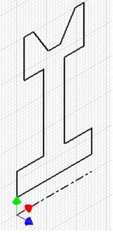
Suggested Base
Sketch – Right Side
View (YZ Plane)
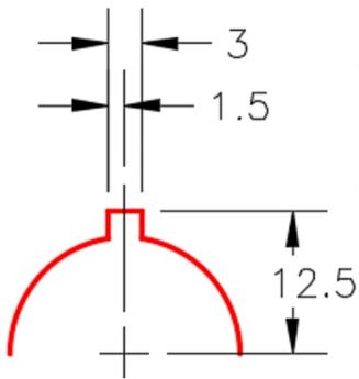
Keyway Detail
Step 2
Draw the necessary sketches and extrude them to complete the model.
Step 3
Apply all of the necessary geometrical and dimensional constraints to fully constrain all sketches. Ensure that all objects, on all sketches, display purple on a black background.
Step 4
Create the fillets after the solid model is totally constructed.
Step 5
Apply the colour shown. (Figure Step 5A and 5B)
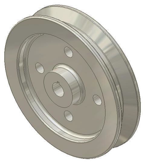
Solid Model – Home View
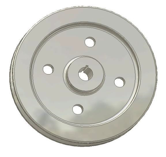
Solid Model – Rotated View