
4.2: Module 18 Editing Geometry
- Page ID
- 19883

18
Module 18 Editing Geometry
Wally Baumback
Learning Outcomes
When you have completed this module, you will be able to:
- Describe how to select objects using windows and crossing windows.
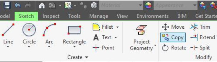
- Describe and apply the THREE POINT ARC, TWO POINT RECTANGLE, and COPY commands.
Methods of Selecting Objects
Selecting Objects
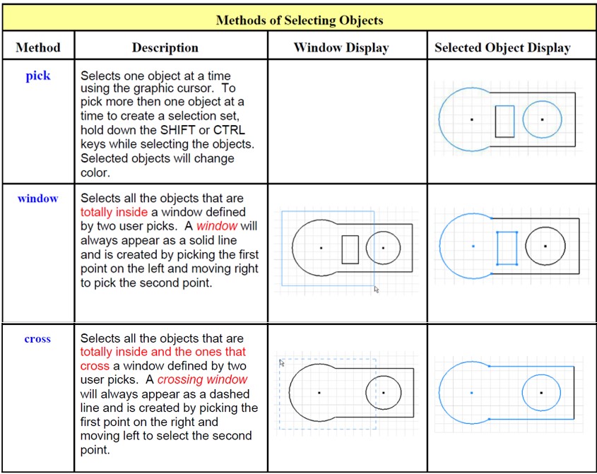
Up to this point in the book, the only way that has been shown how to select objects was to pick them, one at a time. A quicker and more efficient method of selecting multiple objects is to use either a window or a crossing window. Study Figure 18-1 and start using windows and crossing windows when selecting multiple objects in both Sketch or Model mode.
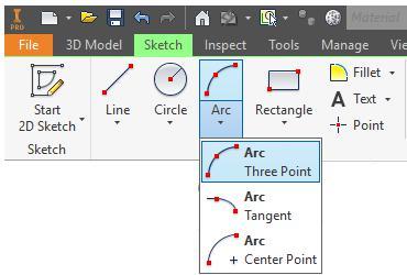
Inventor Command: THREE POINT ARC
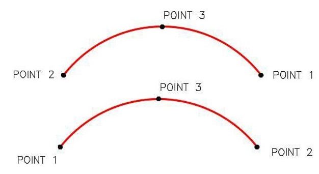
The THREE POINT ARC command is used to draw an arc by selecting the two endpoints of the arc and a third point anywhere on the circumference of the arc.
Shortcut: none
AUTHOR’S COMMENTS: Construct the arc either clockwise or counterclockwise. Point 3 MUST always be on the circumference of the arc, between Point 1 and Point 2. See Figure 18-2.
Construction Techniques for Arcs
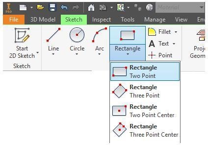
Inventor Command: TWO POINT RECTANGLE
The TWO POINT RECTANGLE command is used to draw a rectangle or a square by selecting two points of its opposite corners.
Shortcut: none
Inventor Command: COPY
The COPY command is used in Sketch mode to copy 2D geometry from one XY location to another.
Shortcut: none
WORK ALONG: Drawing a Solid Model with Arcs and Rectangles
Step 1
Check the current project and if necessary, set it to Inventor Course.
Step 2
Using the NEW command, start a new part file using the template: English-Modules Part (in).ipt.
Step 3
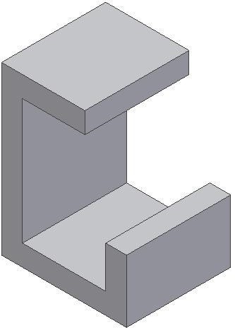
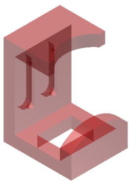
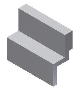
Save the file with the name: Inventor Workalong 18-1. (Figure Step 3A, 3B, 3C, and 3D)
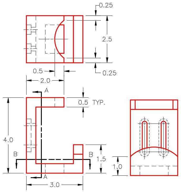
Dimensioned Multiview Drawing [Click to see image full size]
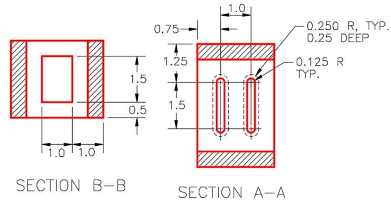
Dimensioned Detail Drawing [Click to see image full size]
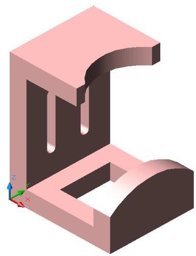
3D Model – Home View [Click to see image full size]
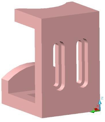
3D Model – Rotated View [Click to see image full size]
Step 4
Start the Base sketch on the Front or XZ plane. Project the Center Point onto the sketch.
Step 5
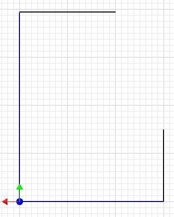
Draw the four outside lines of the Base sketch. (Figure Step 5)
Step 6
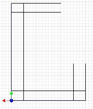
Offset all four lines as shown in the figure. (Figure Step 6)
Step 7
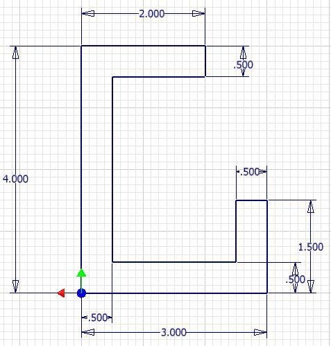
Trim and dimension the sketch ensuring that it is totally constrained. (Figure Step 7)
Step 8
Press F6 to change the view to the Home view. All of the lines in the sketch should appear purple. Extrude the sketch. (Figure Step 8)
Sketching Without the Grid
Up to this point in the Inventor book, the grid display has been enabled in Sketch mode. To the more experienced operator, grid display can be disabled in Sketch mode. On some sketches, it is sometimes easier to draw without the grid getting in the way.
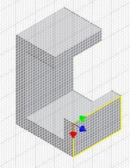
Step 9
Start a new sketch on the right side face as shown in the figure. (Figure Step 9)
Step 10
Using what you already learned, open the Application Options dialogue box.
Step 11
Enable the Sketch tab.
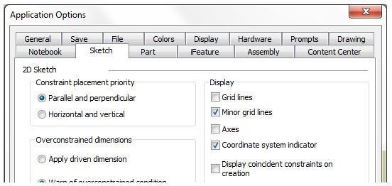
Step 12
In the Display area, disable Grid Lines. (Figure Step 12)
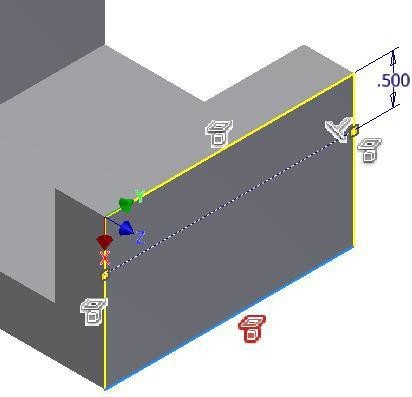
Step 13
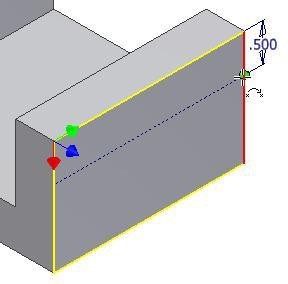
Draw a construction line 0.5 inches below the top edge and dimension it. Ensure that it is fully constrained. (Figure Step 13)
Step 14
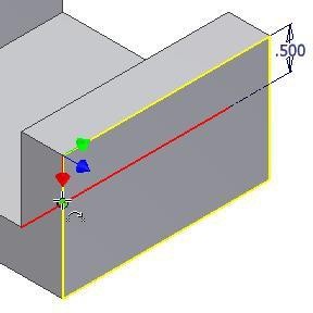
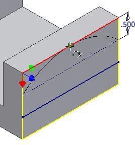
Click the THREE POINT ARC command. Snap the first point to one end of the construction line, snap the second point to the other end of the construction line. For the third point, snap it to the midpoint of the top edge. (Figure Step 14A, 14B, and 14C)
Step 15
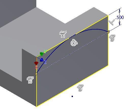
Using the CREATE CONSTRAIN command, apply the Tangent constraint to the arc and the top edge. This should fully constrain the sketch. (Figure Step 15)
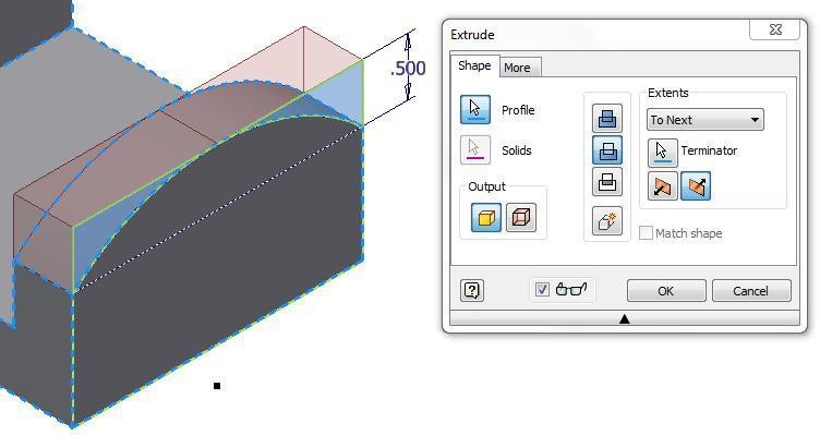
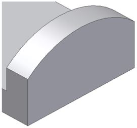
Step 16
Extrude the sketch. (Figure Step 16A and 16B)
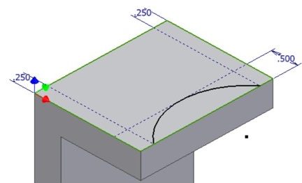
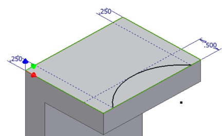
Step 17
Using what you just learned, start a new sketch on the top of the model. On it, draw three construction lines and a three point arc. Ensure that the sketch is fully constrained. Extrude the sketch. (Figure Step 17A and 17B)
Step 18
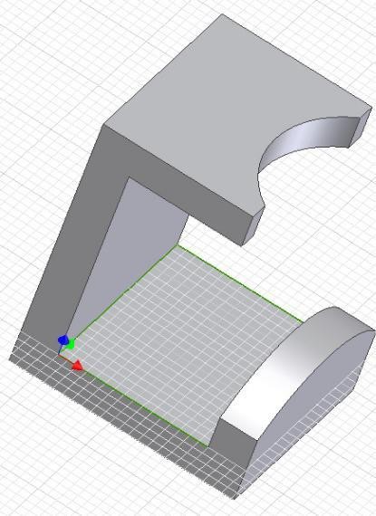
Start a new sketch on the lower plane. (Figure Step 18)
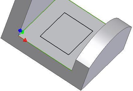
Step 19
On the sketch, using the TWO POINT RECTANGLE command, draw a rectangle by selecting two opposite corners. Guess at the location and size. (Figure Step 19)
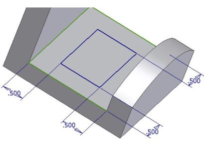
Step 20
Insert four dimensions, one from each edge. Check to ensure that the sketch is fully constrained and extrude it. (Figure Step 20A and 20B)
Step 21
Start a new sketch on the back plane and place a construction line as shown in the figure. Do not offset the edge. Ensure that you constrain the line perpendicular to the bottom or top edge. You can guess at the start point and the length of the line. (Figure Step 21)
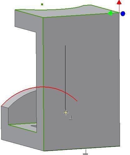
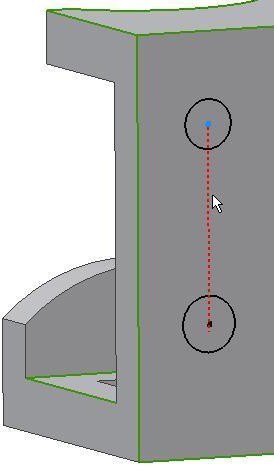
Step 22
Change the property of the line to a construction line. Insert one circle at the each end of the line. Snap to the end of the line to locate the centre of the circles. (Figure Step 22)
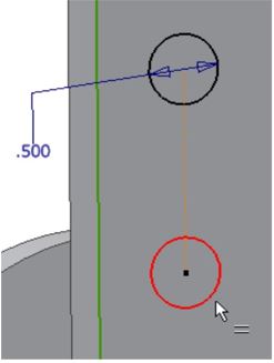
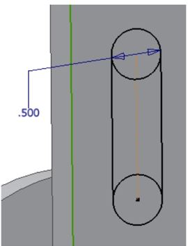
Step 23
Using what you learned already, dimension one of the circles and then create an Equal constraint for the other one. Draw lines on either side of the circle. Ensure that you snap the end of the lines onto the circles. Constrain the lines to the circle with the Tangent constraint. Trim the circles. (Figure Step 23A, 23B, and 23C)
Step 24
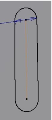
Draw a construction line from the end of the construction line at the top circle, constraining it perpendicular to one of the vertical lines. Draw it approximately 1 inch long. (Figure Step 24)
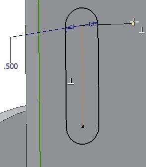
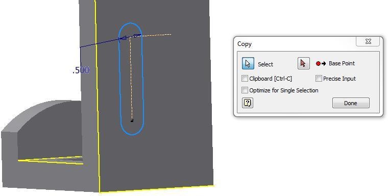
Step 25
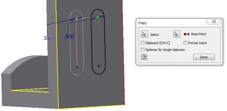
Click the COPY command and select the two lines and the arcs as shown in the figure. Ensure that the Select icon is enabled. (Figure Step 25)
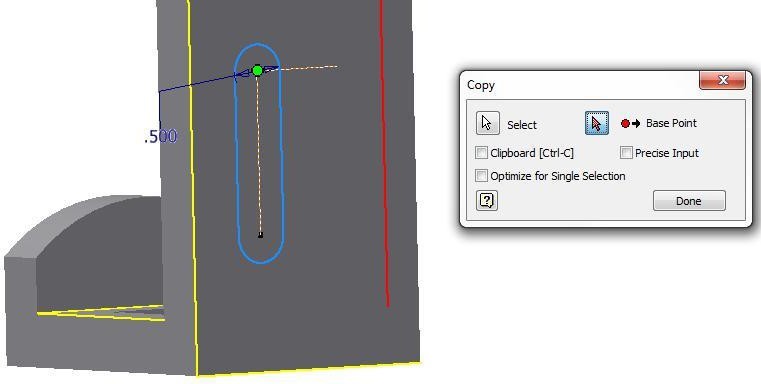
Step 26
Enable the From icon and select the end of the construction line for the From location. (Figure Step 26)
Step 27
Enable the To icon and select the other end of the construction line for the To location. (Figure Step 27)
Step 28
If you get the warning message, click Yes.
Step 29
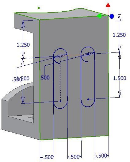
Dimension the sketch until it is fully constrained. (Figure Step 29)
Step 30
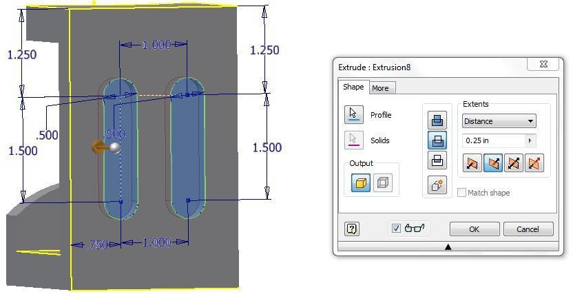
Return to Model mode and extrude the slots. Extrude them 0.25 inches deep. (Figure Step 30)
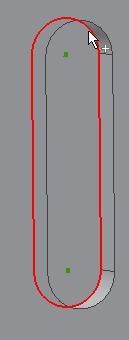
Step 31
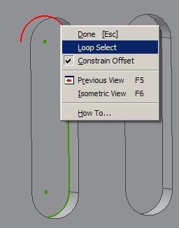
Start a new sketch on the bottom of the extruded slots. Enter the OFFSET command and right-click one of the arcs. In the Right-click menu, enable Loop Select. Select the other arc and the lines to complete the loop. (Figure Step 31A and 31B)
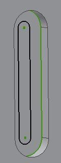
Step 32
Offset the slot towards the inside. Guess at the offset distance. (Figure Step 32)
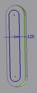
Step 33
Dimension the offset. (Figure Step 33)
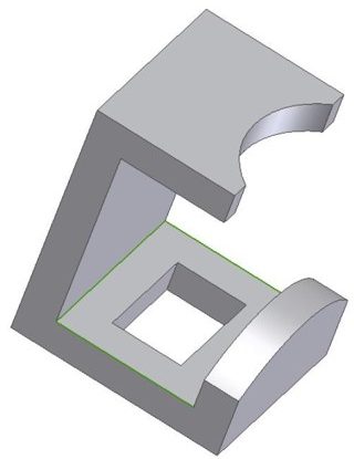
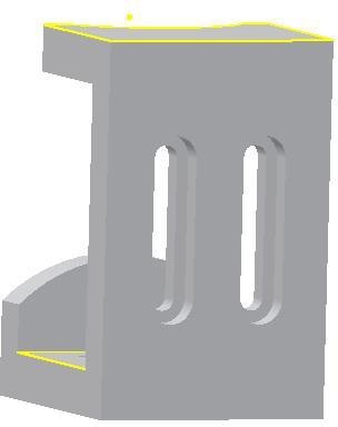
Step 34
Extrude the slot To Next. (Figure Step 34)
Step 35
Redo Step 31 to 34 on the other slot to complete the solid model.
Step 36
Set the colour to: Dark Red. (Figure Step 36)
Step 37
Save and close the file.
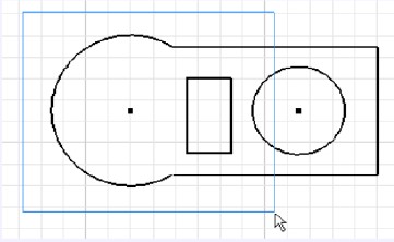
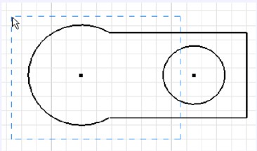
MUST KNOW: A window selects all of the objects that are totally inside of it defined by two user picks. A window always appears as a solid line and is created by picking the first point on the left and moving right to pick the second point.A crossing window selects all of the objects that are totally inside and the ones that cross it defined by two user picks. A crossing Window always appear as dashed lines and is created by picking the first point on the right and moving left to select the second point.
To select a window or crossing window, select the first point by moving the cursor to the desired location and press the left mouse button down. While holding it down, move to the cursor to second desired location and release the mouse button.
Key Principles
Key Principles in Module 18
- A window appears as a solid rectangle selecting only the objects totally inside the window. A crossing window appears as a dashed rectangle selecting all of the objects that it crosses and the ones that are totally inside the crossing window.
Lab Exercise 18-1
Time allowed: 60 minutes.
| Part Name | Project | Units | Template | Color | Material |
| Inventor Lab 18-1 | Inventor Course | Millimeters | Metric-Modules Part (mm).ipt | Zinc | N/A |
Step 1
Project the Center Point onto the base plane.
Step 2
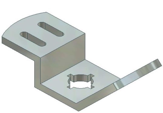
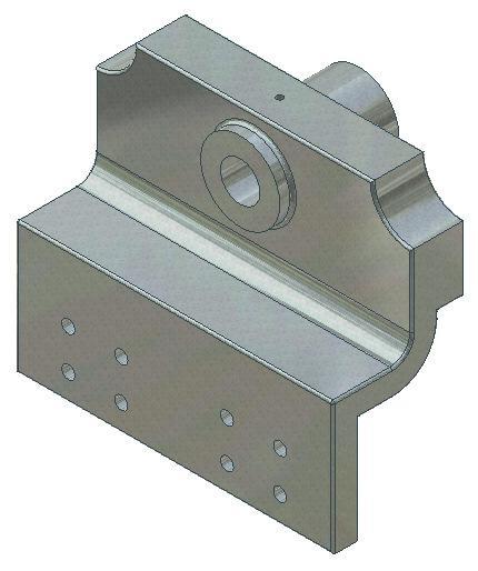
Note the location of X0Y0Z0. Draw the necessary sketches and extrude or revolve them to produce the solid model shown below. Apply all of the necessary geometrical and dimensional constraints to maintain the objects shape and size. (Figure Step 2A, 2B, 2C, and 2D)
3D Model – Home View
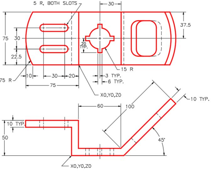
Dimensioned Multiview Drawing [Click to see image full size]
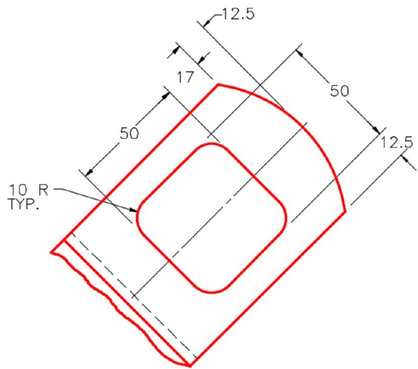
Dimensioned Auxiliary View [Click to see image full size]
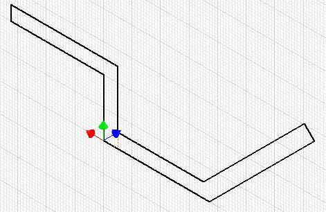
Suggested Base Sketch –
Front (XZ) Plane
Step 3
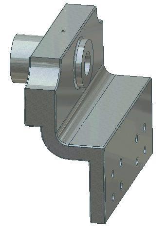
Apply the colour shown above. (Figure Step 3A and 3B)
Solid Model – Home View
Solid Model – Rotated View
Lab Exercise 18-2
Time allowed: 60 minutes.
| Part Name | Project | Units | Template | Color | Material |
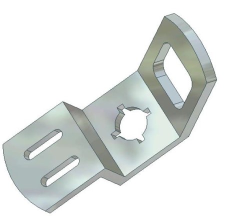
| Inventor Lab 18-2 | Inventor Course | Inches | English-Modules Part (in).ipt | Galvanized (texture) | N/A |
Step 1
Project the Center Point onto the base plane.
Step 2
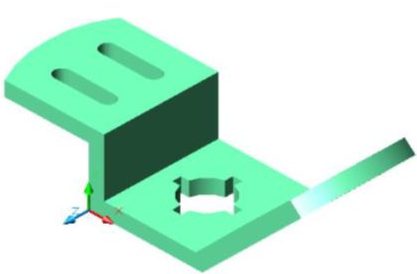
Note the location of X0Y0Z0. Draw the necessary sketches and extrude or revolve them to produce the solid model shown below. Apply all of the necessary geometrical and dimensional constraints to maintain the objects shape and size. (Figure Step 2A and 2B)
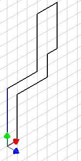
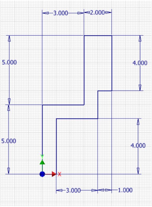
Suggested Base
Sketch – Right Side
(YZ Plane)
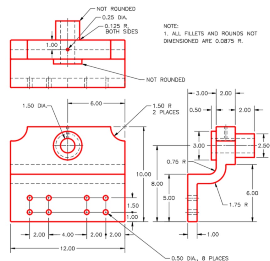
Dimensioned Multiview Drawing
Step 3
Apply the colour shown above. (Figure Step 3A and 3B)
Solid Model – Home View
Solid Model – Rotated View
Step 4
Create all fillets after the solid model is totally constructed.