5.4: Module 25 2D Drawings – Part 2
- Page ID
- 19890
25
Module 25 2D Drawings – Part 2
Wally Baumback
Learning Outcomes
When you have completed this module, you will be able to:
- Describe basic dimensioning, centerlines, and standard styles.
- Describe and apply the STYLES EDITOR command to copy and edit standard styles to create your own dimension and text styles.
- Describe and apply the RETRIEVE DIMENSION, CENTERLINES, and GENERAL DIMENSION commands to place model and drawing dimensions and centerlines on drawing views.
- Describe how styles are exported out of and imported into drawing files.
Drafting Lesson: Basic Dimensioning Terms
Figure 25-1 shows the basic dimensioning terms that you will need to know when setting the standards for dimensioning style.
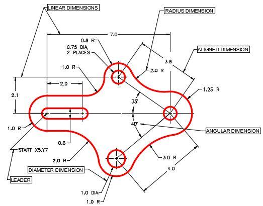
Basic Dimensioning Terminology [Click to see image full size]
Dimensioning
Dimensioning is the process of adding size descriptions to the orthographic views of the model that are placed on a drawing. Once a orthographic views of the model are dimensioned, the drawing sheet can then be plotted and used for construction or reference. Up to this point in the modules only shape and size descriptions have been added to the solid models that are been constructed by adding geometrical and dimensional constraints. Since Inventor knows the exact size of the solid models, the drafter/designer only has to control which dimensions are shown and where to position them.
Dimensioning is a complex subject, not difficult, but there is a lot to learn. Therefore, in the Inventor Modules, learning to control the appearance and location of the basic dimension types is taught. As the Inventor user gets more experience dimensioning he/she can experiment with some of the advanced dimensioning features.
Dimensioning Styles
A dimensioning style is a named set of variables or settings that controls the way the dimensions will appear on the drawing. There are many different settings in a dimensioning style so it will take the user some time to get used to setting them. Be patient and practice editing styles and inserting dimensions as often as possible.
Inventor comes with several preset dimensioning styles which are part of the template that was used when the drawing file was created. They can be edited but cannot be renamed. It is better to create a new style by copying an renaming one of the Inventor standards and make the necessary changes to it. After the editing is complete, name the style with an appropriate name and save it so that it can be identified and used again at a later date. Dimensioning styles can also be exported and imported from one drawing to another.
Text Styles
A text style is a named set of variables or settings that controls the way text will appear on a drawing. Inventor comes with several preset text styles which were part of the template that was used when the drawing file was created. Although they can be edited, they cannot be renamed. If changes are required, it is better to create a new text style by copying one of the Inventor standards and make the necessary changes to it. After the editing is complete name the style with an appropriate name and save it so that it can identified and used at a later date. Text styles can also be exported and imported from one drawing to another.
Centerlines
A centerline is used in technical drawings to indicate the location of the axis of symmetry. Placing centerlines on all objects that have a symmetrical shape will help others who are reading the drawing. The proper use of centerlines also cut down on the number of dimensions that are required on a drawing to fully describe the object.
Placing Dimensions
The two types dimensions that can placed on a drawing are model dimensions and drawing dimensions.
Model Dimensions
Model dimensions are the driven and driving dimensions that were placed in the 2D sketch when the model was being constructed. The RETRIEVE DIMENSION command is used to retrieve the dimensions from the model and display them on the drawing. If the driven dimensions in the original sketches are changed in the future, the model dimensions in the drawing will automatically change since they are showing the actual size of the model.
Drawing Dimensions
Drawing dimensions are dimensions that are placed in the drawing using the GENERAL DIMENSION command. Dimensions are placed exactly where they are located in the 2D sketch when the model was created. Inventor will obtain the actual sizes and if the model is changed in the future, the drawing dimensions will automatically change to reflect the new size of the model.
Inventor Command: STYLES EDITOR
The STYLES EDITOR command is used to create and/or edit the styles and standards used by a drawing file.
Shortcut: none
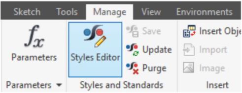
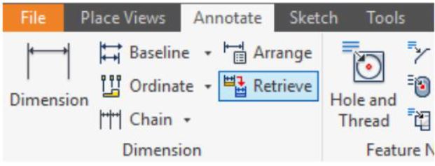
Inventor Command: RETRIEVE DIMENSIONS
The RETRIEVE DIMENSIONS command is used to retrieve model dimensions from the sketches used to create the solid model. Only dimensions that are parallel to the plane of the view will display. The user can select the dimensions that they want to display on the drawing.
Shortcut: none
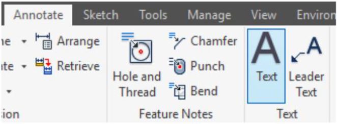
Inventor Command: TEXT
The TEXT command is used to place text on the a drawing sheet. It uses the default text style when the text is inserted.
Shortcut: none
Drafting Lesson: Center Lines
In multiview drawings, the center line is used to indicate the location of the axis of symmetry. Placing centre lines on all objects that have a symmetrical shape will help the reader and save the you from inserting a lot of dimensions as you will see in future modules. Below are some examples of typical applications of the use of centre lines in a multiview drawing.
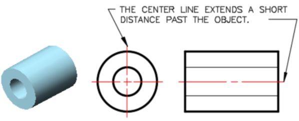
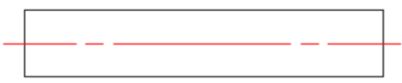
A ‘ C ‘ with an ‘ L ‘ through it is the symbol for a centre line. Center lines are drawn as repeating long and short lines. See Figure 37-2.

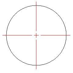
Figure 37-3 shows a centre line indicating the centre of the circle with two short lines called a center mark intersecting at the centre. Note in the right side view, the centre line follows the length of the cylinder.
When the symmetry ends, so does the centre line. Note how the centre line ends on the left side of the arc. See Figure 37-4
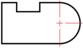
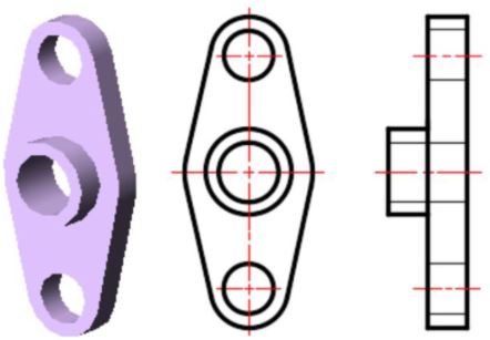
Figure 37-5 shows the centre lines along with the hidden lines that indicate a hole going through the object. The centre line on the top and bottom circles stops at the circle.
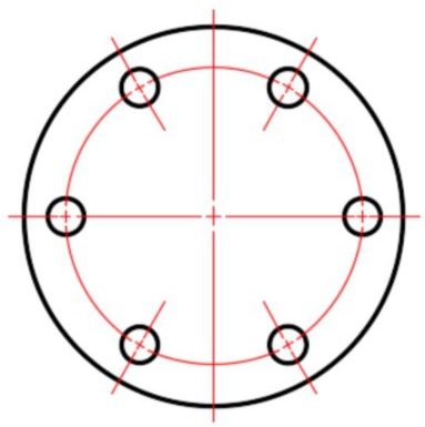
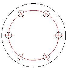
In Figure 37-6, note how centre lines are drawn for an array of circles.
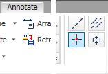
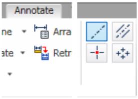
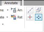
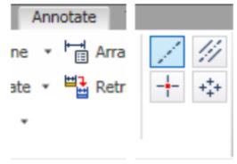
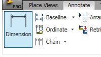
There are four icons used to place centerlines on the drawing. In this module, you will be using three of them. The Center Mark, Centerline, and Centered Pattern icons are shown in Diagrams F1, G1 and H1. Diagrams F2, G2 and H2 show what centerline the applicable icon will place.
WORK ALONG: Creating Dimensioning and Text Styles
Step 1
Check the default project and if necessary, set it to: Inventor Course.
Step 2
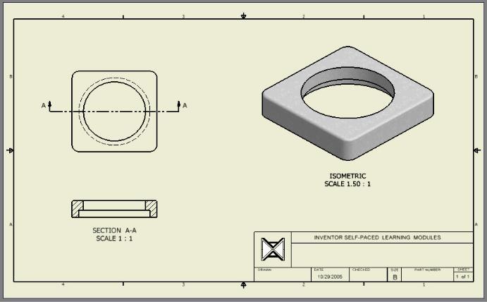
Open the drawing file: Inventor Lab 24-1A.idw. (Figure Step 2)
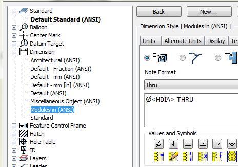
Step 3
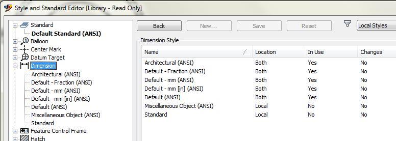
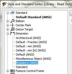
Enter the STYLES EDITOR command to open the Styles and Standard Editor dialogue box. Expand the children under the heading Dimension from the list of styles and standards on the left side of the dialogue box. The seven dimensioning styles listed are the styles that are already contained in your drawing. They were in the template file that you used when you created the drawing. (Figure Step 3)
Step 4
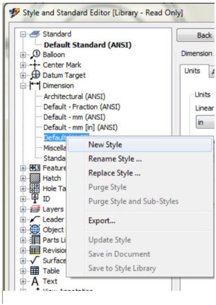
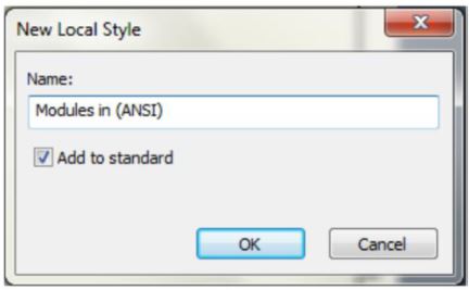
Right-click the dimensioning style: Default (ANSI). In the New Style Name dialogue box, enter the name: Modules in ANSI. Ensure that you enable the Add to Standard and then click OK. (Figure Step 4A and 4B)
Step 5
Click the dimensioning style: Modules in (ANSI) in the style list on the left side of the dialogue box to make it the current style. Note that on the right side of the dialogue box your newly created style is listed at the top above the tabs. This indicates it can be edited in the dialogue box. Enable the Units tab. (Figure Step 5A and 5B).
Step 6
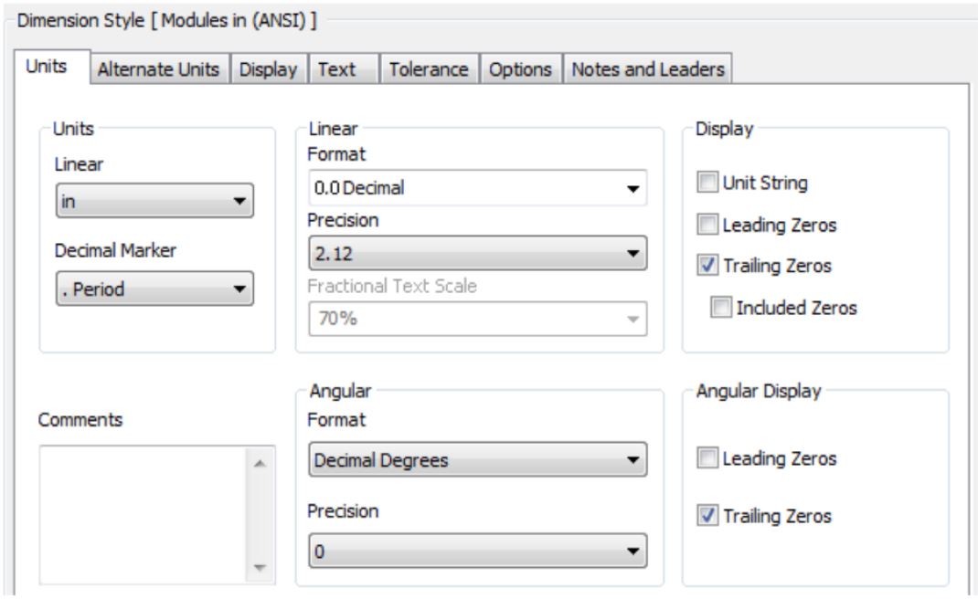
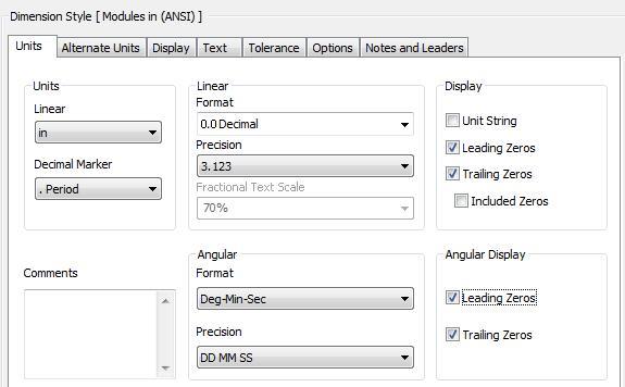
Change the Linear and Angular box to match the settings shown in the figure. (Figure Step 6)
Step 7
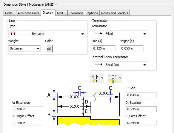
Enable the Display tab and if necessary, make any changes until it matches the figure. (Figure Step 7)
Step 8
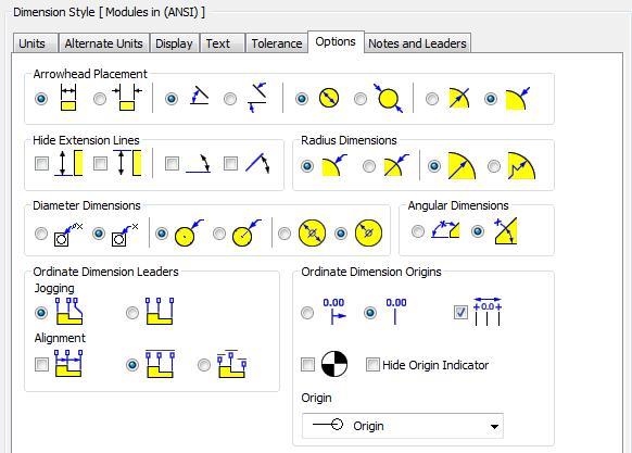
Enable the Options tab and if necessary, make any changes until it matches the figure. (Figure Step 8)
Step 9
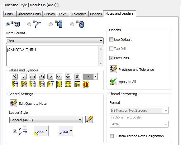
Enable the Notes and Leaders tab and if necessary, make any changes until it matches the figure. (Figure Step 9)
Step 10
Click the Save button to save the changes you made to the dimensioning style: Modules in ANSI. Click Done to close the dialogue box. (Figure Step 10)

Step 11
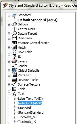
Expand the children under the heading Text from the list of styles and standards on the left side of the dialogue box. The style names listed are the text styles that are already contained in your drawing. (Figure Step 11)
Step 12
Right click the style: Note Text (ANSI). In the right-click menu, select New Style. (Figure Step 12)
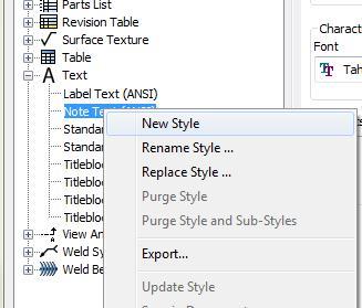
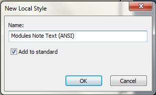
Step 13
This will open the New Style Name dialogue box as shown in the figure. Note that since the text style: Note Text (ANSI) was the current style, you will be starting with a copy of its settings. Enter the name: Modules Note Text (ANSI) and click OK. Ensure that Add to standard is enabled. (Figure Step 13)
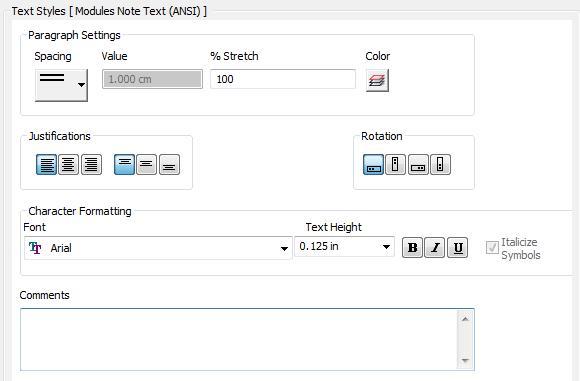
Step 14
Make any changes necessary to match the figure. (Figure Step 14)
Step 15
Click the Save button to save the changes you made to the text style.
Step 16
Use what you learned earlier in the workalong, make the dimensioning style: Modules in ANSI the active style. (Figure Step 16)
Step 17
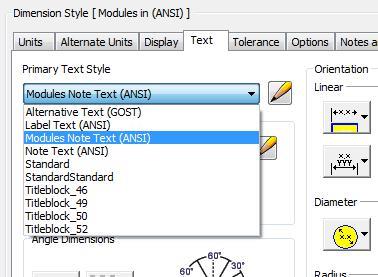
Enable the Text tab. Pull down the Primary Text Style pull-down box and select the text style: Modules Note Text (ANS)I. This will make it the default text style for the dimensioning style: Modules in ANSI. (Figure Step 17)
Step 18
The Text tab in the active dimension style: Modules in ANSI should appear as shown in the figure.
Step 19
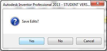
Click the Done button and if you are asked to Save Edits, click Yes. (Figure Step 19)
Step 20
Save and close the drawing file.
WORK ALONG: Adding Annotation to the Drawing
Step 1
Check the default project and if necessary, set it to: Inventor Course.
Step 2
Open the drawing file: Inventor Lab 24-1A.idw.
Step 3
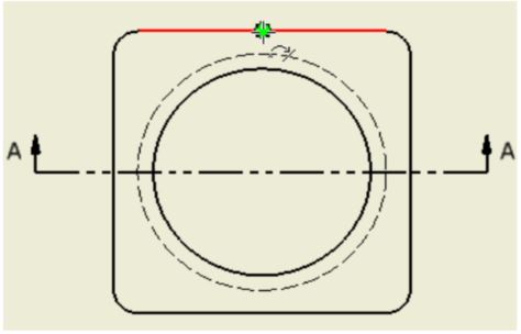
Click the Centerline icon to place the vertical centerline on the Top view. For the first point, snap to the midpoint of the line on the top of the view. For the second point, snap to the midpoint of the bottom line of the Top view. Move the cursor a short distance below the Top view and click it to indicate the distance the centerline is to go past the view. (Figure Step 3A, 3B, 3C, and 3D)
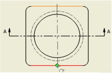
Step 4
Using what you just learned, place the centerline on the Front view. (Figure Step 4)
Step 5
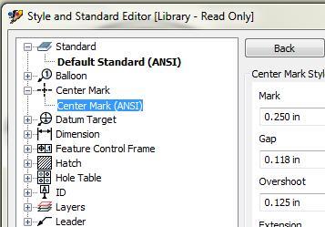
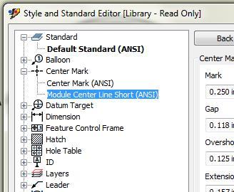
Open the Style and Standard Editor dialogue box. On the left side, expand the children in the Center Mark heading. Select Center Mark (ANSI) to make it the current style. (Figure Step 5)
Step 6
Right-click the standard style: Center Mark (ANSI) and click New Style. In the New Style Name dialogue box, enter the name: Modules Center Line Short (ANSI). (Figure Step 6)
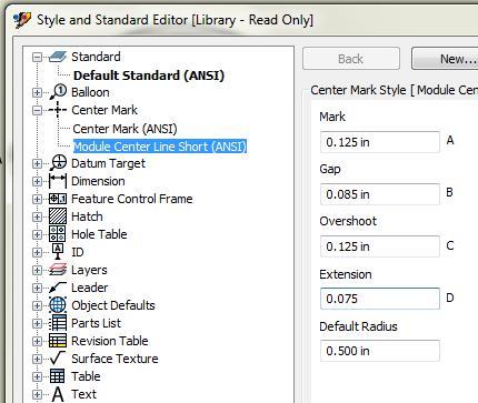
Step 7
Select the new style that you just created to make it the current style. Make the changes shown in the figure. (Figure Step 7)
Step 8
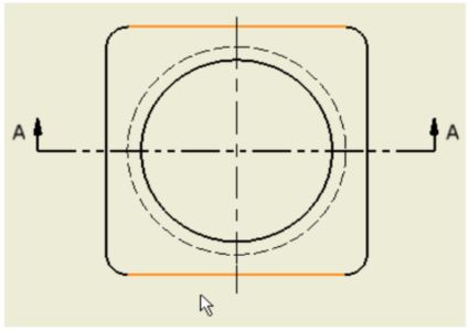
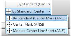
Select the centerline in the Front view. It will highlight. (Figure Step 8)
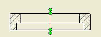
Step 9
With the centerline selected, look on the Inventor Standard pull-down menu. Note how it shows Standard as the centerline type for selected object. Select the centerline style: Modules Center Line Short ANSI. (Figure Step 9A and 9B)
dimensions so that when you create the drawing and dimension the model, it will retrieve all of the dimensions required. That way, you will may not have to place any general dimensions.
Step 10
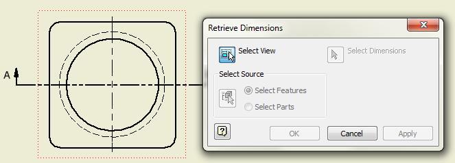
Enter the RETRIEVE DIMENSION command and in the Retrieve Dimensions dialogue box, ensure that Select View icon is enabled. Select the Top view. (Figure Step 10)
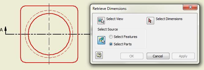
Step 11
In the Select Source box, enable Select Parts. Select all objects. The dimensions that you inserted in the sketches that are parallel to the plane will display. (Figure Step 11)
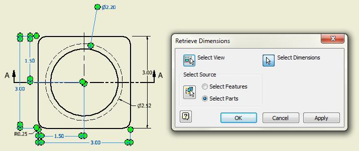
Step 12
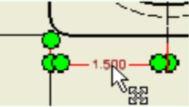
Ensure that the Select Dimension icon is enabled select the dimension(s) that are selected in the figure. (Figure Step 12)
Step 13
Using what you just learned, select the dimensions for the Front view of the model. In this case, there was only one. (Figure Step 13)
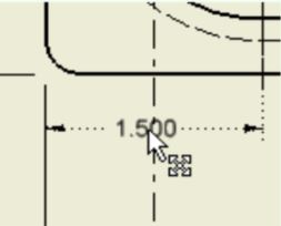
Step 14
Move the dimensions to match the figure as close as possible. (Figure Step 14)
Step 15
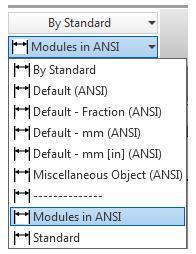
Select all of the dimensions. Change the dimensioning style to: Modules in ANSI. To do this, while the dimensions are selected, pull down the standards list. From the dimension style list, find and select the style: Modules in ANSI in the pull-down list on the Inventor Standard menu. (Figure Step 15A , 15B, and 15C)
Step 16
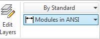
Set the default dimensioning style before you insert the drawing dimensions. Pull-down the style standards list and select: Modules in (ANSI). It should now display as shown in the figure. When you insert your dimensions they will use the default dimensioning style. (Figure Step 16)
Step 17
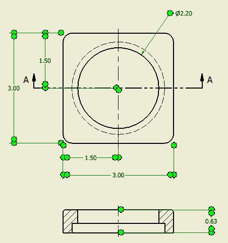
Add the remainder of the dimensions to match the figure. This is done using the GENERAL DIMENSION (D) command, just like you did when creating your 2D sketches. (Figure Step 17A and17B)
Step 18
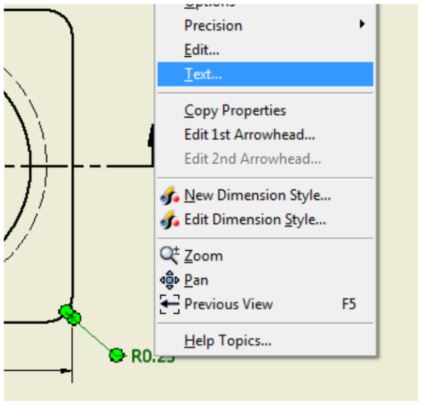
To add or edit dimension text, click the text and right-click the mouse. In the Right-click menu, select Text. This will open the Format Text dialogue box. (Figure Step 18)
Step 19
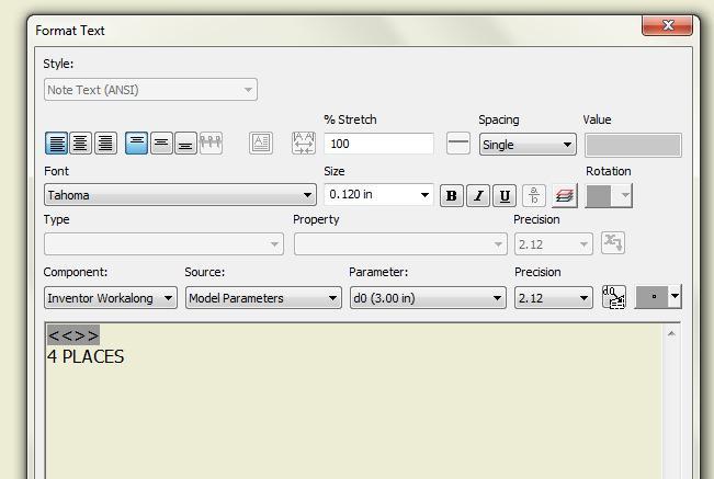
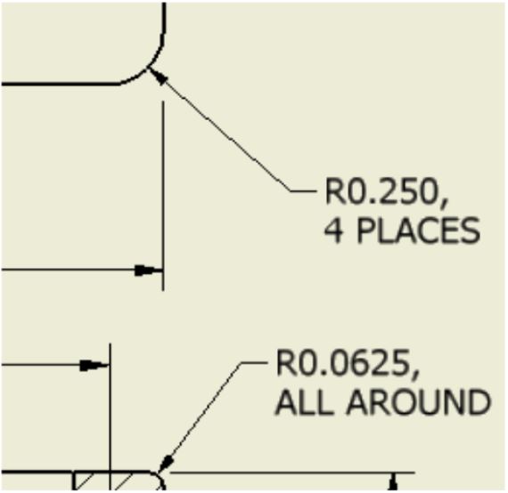
In the text box at the bottom of the dialogue box you will see the symbols << >>. This symbol indicates the actual model dimension. You cannot edit the dimension since Inventor gets the dimension from the model. To add text, click the cursor behind the symbol and enter a comma. Press the Enter key to go to a new line. Add the Figure Step 18 text 4 PLACES. (Figure Step 19)
Step 20
Using what you just learned, add the text to the other radius dimension. (Figure Step 20)
Step 21
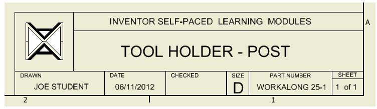
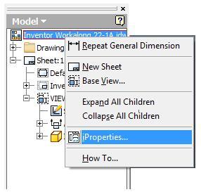
To fill-in the titleblock, simply change the drawing’s properties. To do that, right-click the drawing’s icon in the Browser bar. In the Right-click menu, click iProperties. The titleblock has been programmed to extract the properties of the current drawing file. It will open the Inventor Properties dialogue box. (Figure Step 21)
Step 22
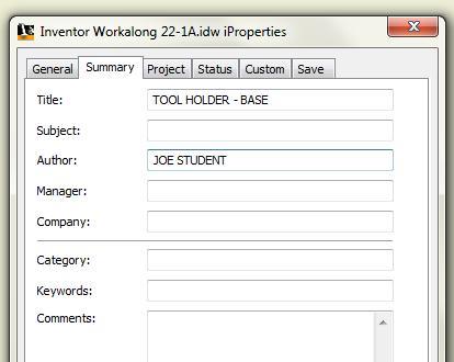
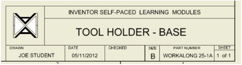
Enable the Summary tab. Enter TOOL HOLDER – BASE in the Title box and your name in the Author box. (Figure Step 22)
Step 23
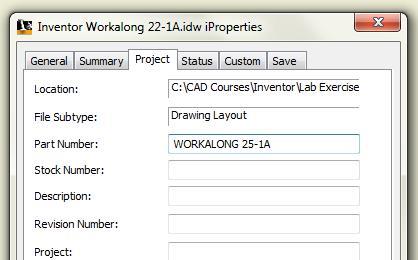
Enable the Project tab. Enter WORKALONG 25-1A in the Part Number box. Your titleblock should now appear as shown in figure. (Figure Step 23A and 23B)
Step 24
Enter the TEXT command and select the location to place the text on the drawing. The cursor will display as a plus sign. Move it to just above the titleblock as shown in the figure. (Figure Step 24)
Step 25
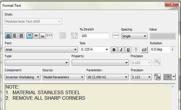
When you select the location for the text, the Format Text dialogue box will open. In the text box along the bottom of the dialogue box enter the text as shown in the figure. Ensure that the default text style is set to: Modules Note Text (ANSI) as shown in the dialogue box. (Figure Step 25)
Step 26
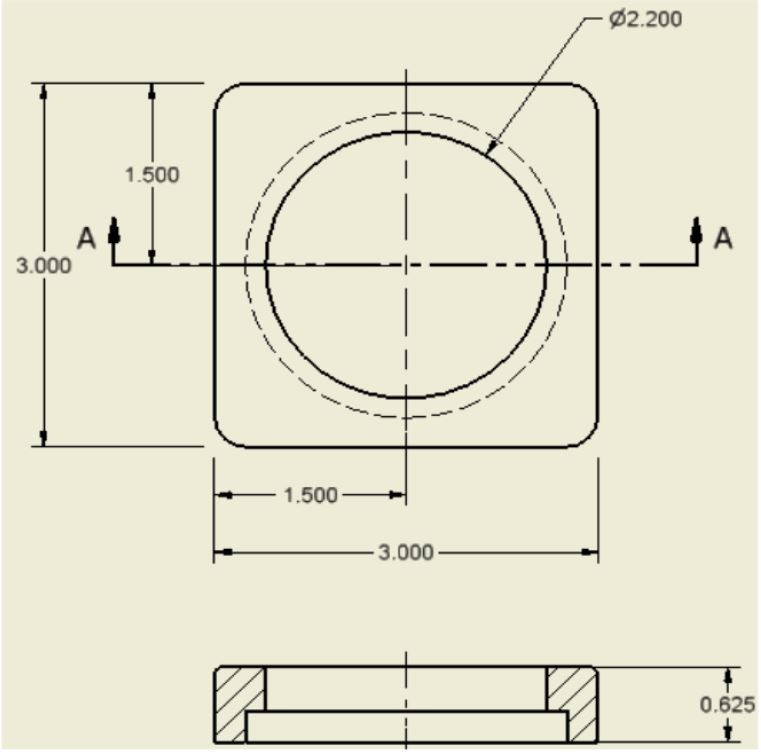
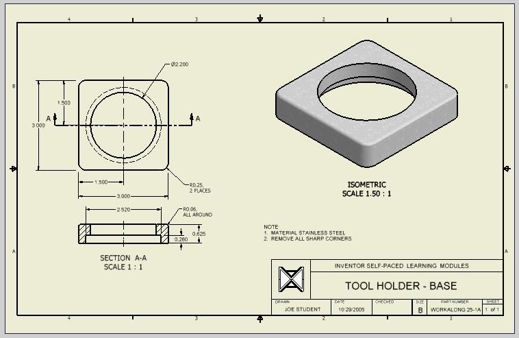
The completed drawing should appear similar to the figure. (Figure Step 26)
Step 27
Save and close the drawing.
Exporting and Importing Styles
When a style is created in a drawing file it is only useable in that drawing file. To save you re-creating the style in each new drawing file, the style can be saved as a file on the hard drive and then retrieve into another drawing. Saving the style file from a drawing is called exporting and retrieving it into a drawing is called importing.
WORK ALONG: Exporting and Importing Styles
Step 1
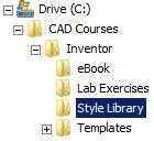
Using Windows Explorer, create the folder: Style Library in the existing folder: C:\CAD Courses\Inventor Course. (Figure Step 1)
Step 2
Start Inventor and check the default project. If necessary, set it to: Inventor Course.
Step 3
Open the drawing: Inventor Lab 24-1A.idw
Step 4
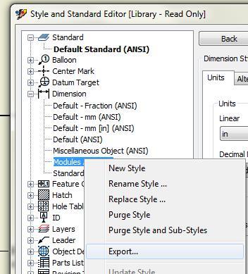
Open the Style and Standard Editor dialogue box. Find and select the style: Modules in (ANSI) under the Dimension heading. It is the dimensioning style that you created earlier in the module. Right-click the name. In the Right-click menu, select Export. (Figure Step 4)
Step 5
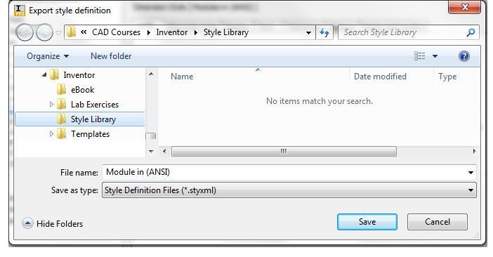
Select the Style Library folder you created in Step 1. In the File name: box, enter the file name: Modules in (ANSI). (Figure Step 5)
Step 6
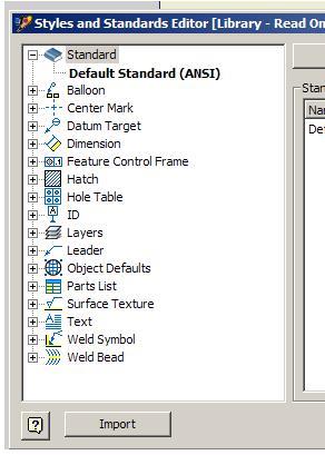
Open a new drawing file. Enter the STYLE EDITOR command and in the dialogue box, click the Import box located along the bottom of the box. (Figure Step 6)
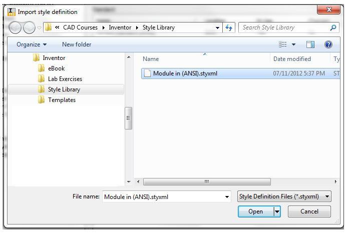
Step 7
This will open the Import style definition dialogue box. Click the folder Style Library and select the file: Modules in (ANSI) .styxml that you exported in Step 5. (Figure Step 7)
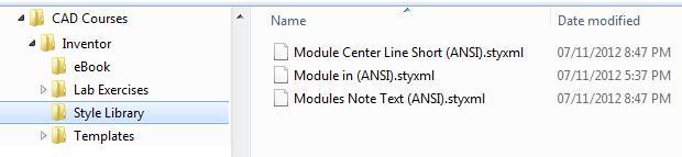
Step 8
Activate the file: Inventor Lab 24-1A.idw and export the other two styles that you created in this drawing. Figure Step 8 shows the three styles that should now be in the Style Library folder. You can check it using Windows Explorer. (Figure Step 8)
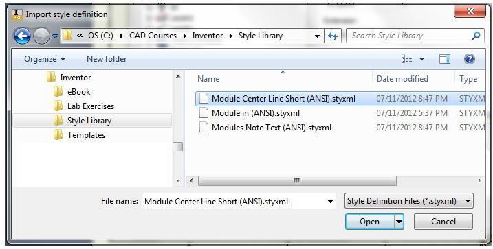
Step 9
Open a new drawing file. Enter the STYLE EDITOR command and in the dialogue box click the Import box located along the bottom of the box. This will open the Import style definition dialogue box. This will open the Import style definition dialogue box. With the Look in: box displaying the folder Style Library, select the file: Modules in (ANSI) .styxml that you exported in Step 5. (Figure Step 9)
Key Principles
Key Principles in Module 25
- The default styles cannot be renamed nor should they be altered. It is always best to create your own named style using a default style to copy from.
- A style is a named set of variables or settings that controls the way the annotation will appear on the drawing.
- The RETRIEVE DIMENSION command is used to retrieve the driven and driving dimensions from the model and display them on the drawing. If the driven dimensions in the original sketches are changed, the model dimensions in the drawing will automatically change.
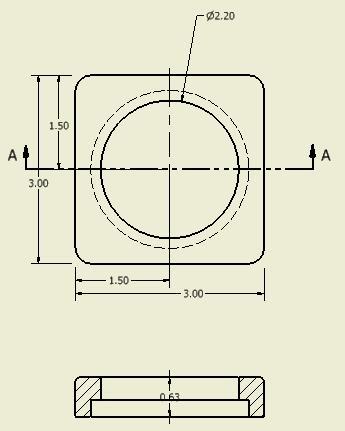
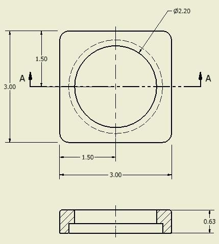
Lab Exercise 25-1
| Part Name | Project | Units | Template | Color | Material |
| See Below | Inventor Course | Inches | See Below | N/A | N/A |
Step 1
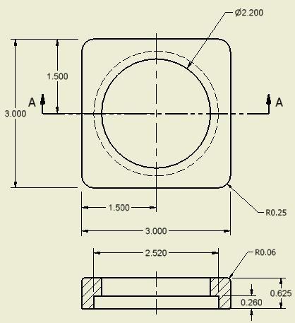
Create the drawing shown below. Ensure that you:
A Retrieve as many model dimensions as you can.
B Add the drawing dimensions to complete the drawing as shown below.
C Import the dimension style: Modules in (ANSI) and use it as the dimensioning style in your drawing. Match the drawing shown below.
D Save the drawing files with the drawing name shown below.
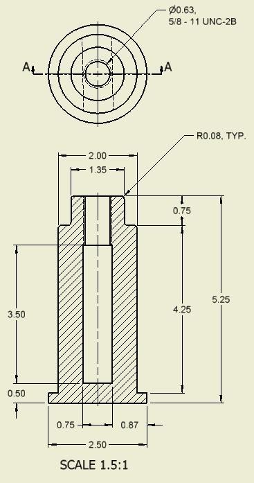
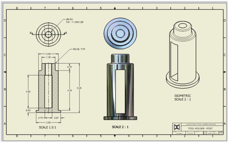
Part: Post
Drawing Size: D
Drawing Name: Inventor Lab 25-1.idw
Part Name: Inventor Workalong 22-1B.ipt
Template: English-Modules Drawing ANSI (in).idw (Figure Step 1A, 1B, and 1C)