
10.6: The J-K Flip-Flop
- Page ID
- 968

Another variation on a theme of bistable multivibrators is the J-K flip-flop. Essentially, this is a modified version of an S-R flip-flop with no “invalid” or “illegal” output state. Look closely at the following diagram to see how this is accomplished:
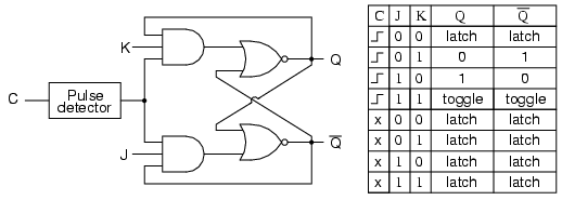
he J and K Inputs
What used to be the S and R inputs are now called the J and K inputs, respectively. The old two-input AND gates have been replaced with 3-input AND gates, and the third input of each gate receives feedback from the Q and not-Q outputs. What this does for us is permit the J input to have effect only when the circuit is reset, and permit the K input to have effect only when the circuit is set. In other words, the two inputs are interlocked, to use a relay logic term, so that they cannot both be activated simultaneously. If the circuit is “set,” the J input is inhibited by the 0 status of not-Q through the lower AND gate; if the circuit is “reset,” the K input is inhibited by the 0 status of Q through the upper AND gate.
When both J and K inputs are 1, however, something unique happens. Because of the selective inhibiting action of those 3-input AND gates, a “set” state inhibits input J so that the flip-flop acts as if J=0 while K=1 when in fact both are 1. On the next clock pulse, the outputs will switch (“toggle”) from set (Q=1 and not-Q=0) to reset (Q=0 and not-Q=1). Conversely, a “reset” state inhibits input K so that the flip-flop acts as if J=1 and K=0 when in fact both are 1. The next clock pulse toggles the circuit again from reset to set.
Logical Sequence of J-K Flip-Flop
See if you can follow this logical sequence with the ladder logic equivalent of the J-K flip-flop:
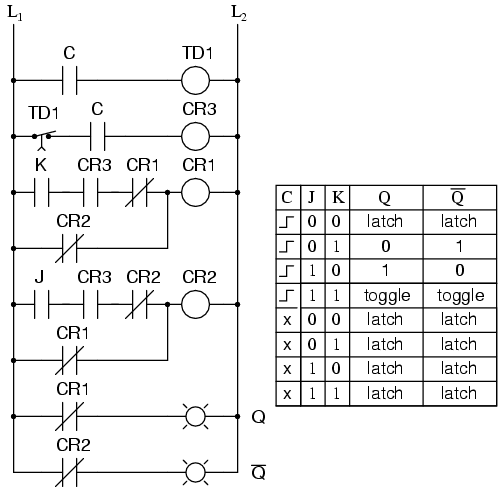
The end result is that the S-R flip-flop’s “invalid” state is eliminated (along with the race condition it engendered) and we get a useful feature as a bonus: the ability to toggle between the two (bistable) output states with every transition of the clock input signal.
There is no such thing as a J-K latch, only J-K flip-flops. Without the edge-triggering of the clock input, the circuit would continuously toggle between its two output states when both J and K were held high (1), making it an astable device instead of a bistable device in that circumstance. If we want to preserve bistable operation for all combinations of input states, we must use edge-triggering so that it toggles only when we tell it to, one step (clock pulse) at a time.
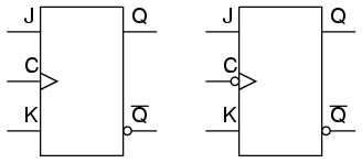
The Block Symbol for J-K Flip-Flops
The block symbol for a J-K flip-flop is a whole lot less frightening than its internal circuitry, and just like the S-R and D flip-flops, J-K flip-flops come in two clock varieties (negative and positive edge-triggered):
Review
- A J-K flip-flop is nothing more than an S-R flip-flop with an added layer of feedback. This feedback selectively enables one of the two set/reset inputs so that they cannot both carry an active signal to the multivibrator circuit, thus eliminating the invalid condition.
- When both J and K inputs are activated, and the clock input is pulsed, the outputs (Q and not-Q) will swap states. That is, the circuit will toggle from a set state to a reset state or vice versa.