
12.6: Introduction to resistance measurements
- Page ID
- 3508
You have studied voltage and current measurements, but you will find resistance measurements different in several ways. Resistance is measured with the circuit’s power turned off. The ohmmeter applies its own voltage to the unknown resistance and then measures the current it produces to calculate a resistance value readout.
Role of the battery
Even though it reads out resistance, the ohmmeter is still a current-measuring device at heart. The ohmmeter is created from a DC meter by adding a group of resistors (called multiplier resistors) and an internal battery. The battery supplies the current flow that is eventually measured by the meter. For this reason, use an ohmmeter only on dead circuits.
In the process of measuring resistance, the test leads are inserted in the meter jacks. The leads are then attached to the ends of whatever resistance is to be measured. Since current can flow either way through a pure resistance, there is no polarity requirement for attaching the meter leads. The meter’s battery sends a current flow through the unknown resistance, the meter’s internal resistors, and the current meter.
The ohmmeter is designed to display 0 Ω when the test leads are clipped together (zero external resistance). When the leads are left open, the meter reads infinite (I) resistance or over-limit (OL) resistance. When a resistance is placed between the leads, the readout increases according to how much current that resistance allows to flow.
An ohmmeter should never be left on the ohms function when not in use to conserve its battery. Since the current available from the meter depends on the battery's state of charge, the DMM should be zero adjusted to start. This may require no more than a test of touching the two probes together.
Figure \(\PageIndex{1}\) shows how resistance measurements are taken.
Note
1 000 Ω = 1 kΩ
1 000 000 Ω = 1 MΩ
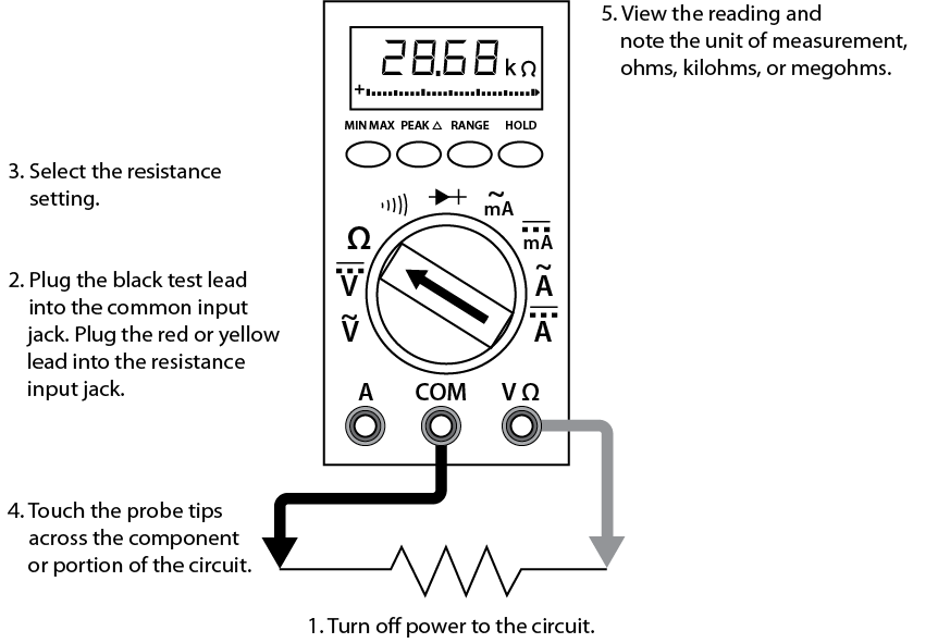
Resistance measurement procedures
Follow the steps below to measure resistance:
- Turn off the power to the circuit. Remove or isolate the component to be tested.
- Plug the test probes into the appropriate probe jacks. Note that the jacks used may be the same ones used to measure volts.
- Select the ohms function by turning the function switch to ohms. Start with the lowest setting.
- Touch the probes together to check the leads, connections, and battery life. The meter should display zero or a minimal amount of resistance for the test leads. With the leads apart, the meter should display OL or I, depending on the manufacturer.
- Connect the tips of the probes across the break in the component or portion of the circuit for which you want to determine resistance. If you get an OL (over limit), move to the next level.
- View the reading on the display unit. Be sure to note the unit of measurement.
- After all the resistance readings are complete, turn the DMM off to prevent the battery from draining
To measure the resistance of components in a circuit, disconnect all but one load. This prevents loss of correct orientation when reconnecting.
You can use the same connection procedure to verify that a circuit, wire, fuse, or switch is complete with no open. This is called a continuity test, and most DMMs will have an audible continuity setting ( ). If there is no audible alarm, then the circuit is broken, or there is too much resistance. A good example is testing a heating element when the element is burned out.
 Now complete the Learning Task Self-Test.