
1.2: Electrical circuits and units of measurement
- Page ID
- 3264
Electrical circuits and units of measurement
The term circuit refers to a circular journey or loop. In the case of an electrical circuit, it is the closed path or loop travelled by the electrons. The movement or flow of electrons (current) is predictable and measurable, depending on a number of variables within the circuit.
Polarity
Electrical polarity (positive and negative) is present in every electrical circuit. Electrons flow from the negative pole to the positive pole. In a direct current (DC) circuit, one pole is always negative, the other pole is always positive, and the electrons flow in one direction only. In an alternating current (AC) circuit, the two poles alternate between negative and positive, and the direction of the electron flow reverses.
Circuit components
A closed circuit provides a complete path for the flow of electrons through conductors. Included in this circuit there must be a resistance (or load), which will do the work and some form of control. For a circuit to be operational it must contain some basic components (Figure 5). These include:
- power source
- conductors
- controls
- load
- protection
Power source
In equipment, the power source is the battery when the engine is off and the generator when the engine is running. In most buildings, it is the power supplied by the local service provider.
Conductors
Conductors are wires or cables wrapped in insulation that carry the current in the circuit. A common ground circuit conductor could be the frame or body of the equipment or the frame on a vehicle.
Controls
Switches are used to turn the current on and off or to regulate the flow of electricity. Switches can be operated mechanically by vacuum, pressure, or electricity.
Load
The load converts electrical energy to work, such as with electric motors, bulbs, heater coils, or horns.
Protection
Fuses, circuit breakers, or fusible links must be used to prevent damage to the source, load, and conductors.
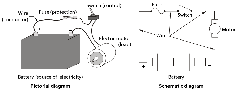
- Basic circuit
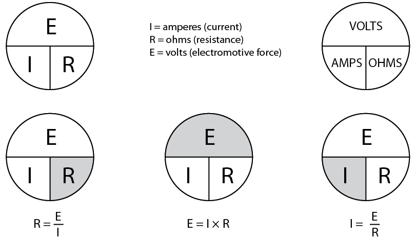
Figure \(\PageIndex{1}\): (CC BY-NC-SA; BC Industry Training Authority) - Ohm’s law circuit aid
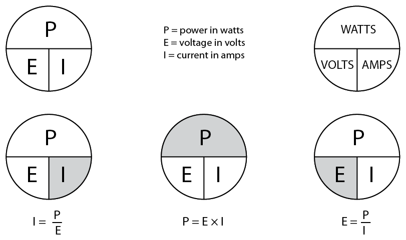
Figure \(\PageIndex{1}\): (CC BY-NC-SA; BC Industry Training Authority) - Power circuit aid
Try to solve the following questions for power, using Ohm’s law calculations.
- How many amps will flow through a 96 W headlight bulb in a 12 V system?
The formula is I = P ÷ E.
Therefore I = 96 W ÷ 12 V.
The result is I = 8 A.
This could be an important consideration in selecting the correct circuit protection device. A fuse with a rating of more than 8 A would have to be chosen in this situation.
- How much power will a soldering gun produce if it uses 6 A in a 120 V electrical system?
The formula is P = E × I.
Therefore P = 120 V × 6 A.
The result is P = 720 W.
Soldering guns are rated in watts. The higher the wattage rating of the gun, the more heat it will produce.
 Now complete the Learning Task Self-Test.
 - How many amps will flow through a 96 W headlight bulb in a 12 V system?