
10.3: Soldering techniques
- Page ID
- 3540
To avoid soldering problems, it is extremely important to work with clean materials and the correct amount of heat. Soldering problems can normally be avoided by bringing the metals to soldering temperature quickly and completing the solder application in a short period of time. You know you have the proper heat when a joint can be completed in about two seconds. The heat will transfer most effectively to the work if a clean tip is lightly tinned with a film of solder. The film of solder will create a bridge between the iron and soldering surfaces by flowing into all gaps. Sometimes a small amount of solder must be added to help form this bridge by applying a small drop to the iron’s tip before applying it to the work surfaces.
Although learning the theories of good soldering is important in developing soldering skills, good soldering is primarily learned through practice. Holding the iron and applying it and the solder to the work surface must be done using techniques that are comfortable and natural to each individual. How you do the job is unimportant as long as the end result is a quality soldered joint with no damage to the surrounding components and materials. At every opportunity, you should experiment with different techniques, always making certain that your soldering meets the requirements of effective soldering listed earlier.
Procedures
To solder effectively, follow these procedures:
- Follow safety precautions.
Always wear safety glasses with side shields when soldering. Ensure adequate ventilation or use solder fume extraction hoods to prevent accumulation of solder fumes. Wear closed-toed shoes and clothing made of natural fibres, with long sleeves and long trouser legs to protect against burns from solder splashes.Avoid touching the solder pencil tip or freshly soldered joints. Use an iron holder and allow the iron to cool completely before putting it away. Never solder on equipment that has power supplied to it. Before eating, drinking, or smoking, always wash your hands to avoid accidentally ingesting lead.
- Clean and tin host materials.
The materials to be soldered (leads, pads, terminals, etc.) must be clean and tinned. Inspect all host metals and clean them to remove contaminants such as oxides, machine oil, hand lotion, and skin oils. Avoid touching cleaned surfaces.
Most component leads and hookup wires are factory tinned. Copper parts and solder pads that are untinned should be cleaned and tinned separately.
To tin a surface, clean it and then heat the surface with a soldering tip. Apply the solder to the surface and allow a thin coating to form on the surface. Allow the surface to cool.
When tinning stranded insulated wires, strip the wire to the appropriate length for the joint being made. Tin the wire, using only enough solder to make the stripped wire solid. The strands of wire should be visible through the solder. Avoid solder from wicking in the wire underneath the insulation.
When tinning and soldering, make a solder bridge to increase the linkage area and speed heating of the surface or joint (Figure 5).
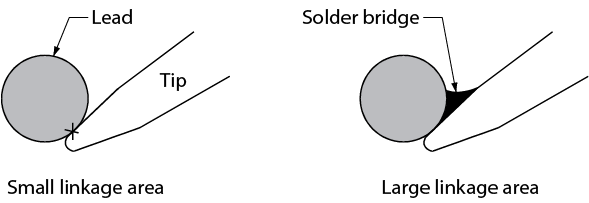
- Cross-section view of iron tip on a round lead - “X” shows point of contact
- Form a mechanical joint between the host metals.

Figure \(\PageIndex{1}\): (CC BY-NC-SA; BC Industry Training Authority) - Needle-nose pliers used as a heat sink
- Allow the connection to cool undisturbed.
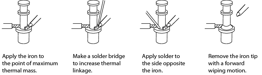
Figure \(\PageIndex{1}\): (CC BY-NC-SA; BC Industry Training Authority) - Steps to solder conductors to turret terminals
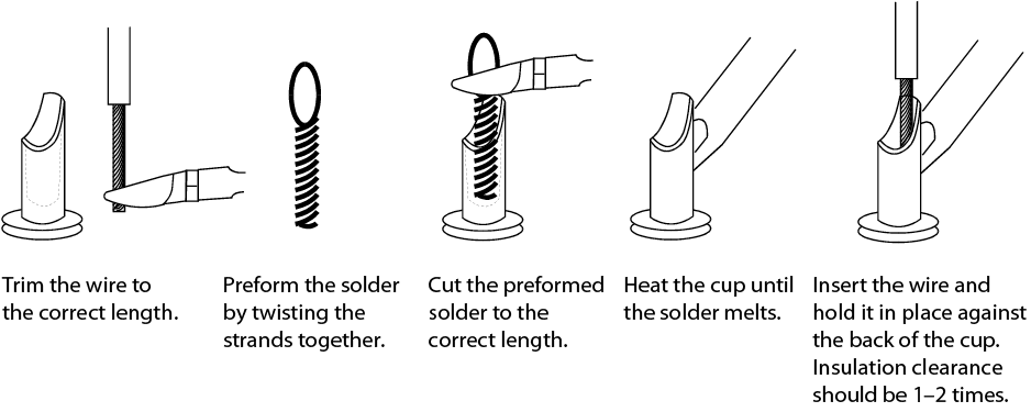
Figure \(\PageIndex{1}\): (CC BY-NC-SA; BC Industry Training Authority) - Soldering procedures for cup terminals
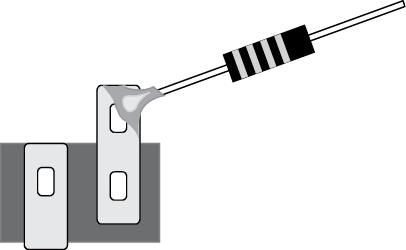
Figure \(\PageIndex{1}\): (CC BY-NC-SA; BC Industry Training Authority) - Correctly soldered connection
Soldering defects
The following characteristics are unacceptable in a solder joint:
- charred, burned, or melted insulation or parts
- excessive solder, including peaks, icicles, and bridging
- flux residue, solder splatter, or other foreign materials on circuitry of adjacent areas
- insufficient solder
- pits, holes, or voids or exposed base metal in the soldered connection
- fractured or cracked solder connection or evidence of grain change
- cut, nicked, gouged, or scraped conductors
- improper conductor length
During the soldering process, you must be very careful to avoid defects in the solder joint itself. Soldering defects primarily reduce the efficiency of the electrical connection between the metals to be joined.
Cold solder joint
A cold solder joint occurs when the component leads have not been heated sufficiently. A lack of heat in the metals to be joined will reduce or eliminate proper wetting of the surfaces, as described earlier. Insufficient wetting will cause the solder to pile up on the joint surface rather than flow smoothly through the joint. An efficient electrical connection between the metals to be joined will not be made, resulting in resistance to current flow through the joint.
Cold joints commonly result from applying solder to the soldering iron’s tip rather than to the joint to be soldered. When the solder is touched to the iron rather than to the joint, the solder will melt before the joint has heated sufficiently. The melted solder will flow over the joint, but will not properly wet it. Unless heat is maintained well after the solder flows over the joint, a cold solder joint will usually occur.
The major indicator of a cold solder joint is a frosty appearance to the surface of the solder. In some instances, reheating the joint adequately will correct a cold joint. If the surface stays frosty, the used solder must be removed and the joint resoldered using correct procedures.
Fractured joint
A fractured joint occurs during the cooling process when the soldered joint is moved while the solder is in its plastic state. Movement during the plastic state will have a crystallizing effect on the solder and a very rough, inefficient joint will result.
The usual cause of a fractured joint is a poor mechanical connection of the metals before soldering begins. Components must be mounted firmly before soldering begins.
Reheating usually cures a fractured joint, but the addition of a small amount of fresh solder may be needed to reflux the exposed metals.
Rosin joint
A rosin joint occurs when part of the joint has been heated enough to melt the flux and coat the metals, but not enough to cause the solder to flow. The covering of flux acts as an insulator and consequently provides a very poor electrical connection or no connection at all.
Reheating and applying a small drop of fresh solder will often cure a rosin joint.
 Now complete the Learning Task Self-Test.
- Form a mechanical joint between the host metals.