
3.2: Homework 3
- Page ID
- 5128

\( \newcommand{\vecs}[1]{\overset { \scriptstyle \rightharpoonup} {\mathbf{#1}} } \) \( \newcommand{\vecd}[1]{\overset{-\!-\!\rightharpoonup}{\vphantom{a}\smash {#1}}} \)\(\newcommand{\id}{\mathrm{id}}\) \( \newcommand{\Span}{\mathrm{span}}\) \( \newcommand{\kernel}{\mathrm{null}\,}\) \( \newcommand{\range}{\mathrm{range}\,}\) \( \newcommand{\RealPart}{\mathrm{Re}}\) \( \newcommand{\ImaginaryPart}{\mathrm{Im}}\) \( \newcommand{\Argument}{\mathrm{Arg}}\) \( \newcommand{\norm}[1]{\| #1 \|}\) \( \newcommand{\inner}[2]{\langle #1, #2 \rangle}\) \( \newcommand{\Span}{\mathrm{span}}\) \(\newcommand{\id}{\mathrm{id}}\) \( \newcommand{\Span}{\mathrm{span}}\) \( \newcommand{\kernel}{\mathrm{null}\,}\) \( \newcommand{\range}{\mathrm{range}\,}\) \( \newcommand{\RealPart}{\mathrm{Re}}\) \( \newcommand{\ImaginaryPart}{\mathrm{Im}}\) \( \newcommand{\Argument}{\mathrm{Arg}}\) \( \newcommand{\norm}[1]{\| #1 \|}\) \( \newcommand{\inner}[2]{\langle #1, #2 \rangle}\) \( \newcommand{\Span}{\mathrm{span}}\)\(\newcommand{\AA}{\unicode[.8,0]{x212B}}\)
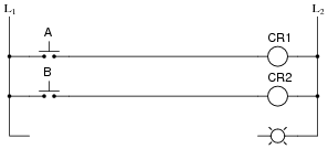
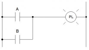
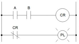
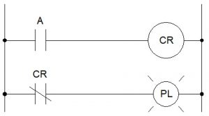
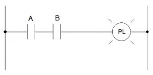
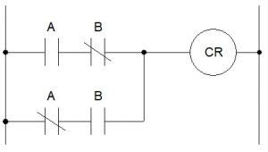
- Create a truth table for each of the following circuits and identify the logical function of each (what’s it take for the pilot light to energize?).
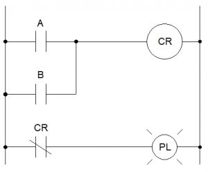
- You’ve been given a partial ladder diagram. Finish the diagram so that an OR function is formed (the indicator lamp energizes if either button A OR B is actuated).
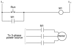
- Analyze this AC motor control circuit diagram, explaining the meaning of each symbol. Also, explain the operation of this motor control circuit. What happens when someone pushes the “Run” button? What happens when they let go of the “Run” button? When does the motor stop?
- The L-side of the contactor is often known as the _______ side, while the T-side of the contactor is often known as the _______ side.
- What do the auxiliary contacts of a contactor do?
- Describe, in your own words, the difference between pick-up, hold-in, and dropout voltage.
- According to the video, how much greater is inrush current than full load current?
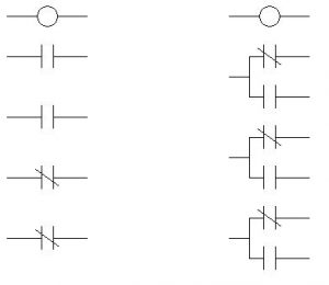
- Use IEC numbering to label the following two schematics (you can re-draw these on separate paper, if necessary):
- List 5 possible causes of overload in an industrial setting.
- What are the two components of a motor starter?
- What’s the difference between a manual and automatic reset on an overload relay?
- Name three types of overloads discussed in the video.
- Draw the NEMA schematic symbol for an overload and show how overloads are represented in a ladder diagram.
- Draw a diagram (not one used in the video) of a 2-wire circuit.
- Draw a diagram (not one used in the video) of a 3-wire circuit.
This chapter is an adaptation of Lessons in Electric Circuits by Tony R. Kuphaldt (on allaboutcircuits.com), and is used under a Design Science License.
Media Attributions
- Relay Schematics