
13.6: Successive Approximation ADC
- Page ID
- 999

One method of addressing the digital ramp ADC’s shortcomings is the so-called successive-approximation ADC. The only change in this design is a very special counter circuit known as a successive-approximation register. Instead of counting up in binary sequence, this register counts by trying all values of bits starting with the most-significant bit and finishing at the least-significant bit. Throughout the count process, the register monitors the comparator’s output to see if the binary count is less than or greater than the analog signal input, adjusting the bit values accordingly. The way the register counts is identical to the “trial-and-fit” method of decimal-to-binary conversion, whereby different values of bits are tried from MSB to LSB to get a binary number that equals the original decimal number. The advantage to this counting strategy is much faster results: the DAC output converges on the analog signal input in much larger steps than with the 0-to-full count sequence of a regular counter.
Without showing the inner workings of the successive-approximation register (SAR), the circuit looks like this:
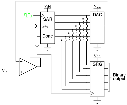
It should be noted that the SAR is generally capable of outputting the binary number in serial (one bit at a time) format, thus eliminating the need for a shift register. Plotted over time, the operation of a successive-approximation ADC looks like this:
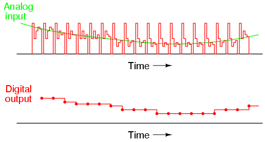
Note how the updates for this ADC occur at regular intervals, unlike the digital ramp ADC circuit.