
6.9: PWM Power Controller
- Page ID
- 2198

PARTS AND MATERIALS
- Four 6 volt batteries
- One capacitor, 100 µF electrolytic, 35 WVDC (Radio Shack catalog # 272-1028 or equivalent)
- One capacitor, 0.1 µF, non-polarized (Radio Shack catalog # 272-135)
- One 555 timer IC (Radio Shack catalog # 276-1723)
- Dual operational amplifier, model 1458 recommended (Radio Shack catalog # 276-038)
- One NPN power transistor—(Radio Shack catalog # 276-2041 or equivalent)
- Three 1N4001 rectifying diodes (Radio Shack catalog # 276-1101)
- One 10 kΩ potentiometer, linear taper (Radio Shack catalog # 271-1715)
- One 33 kΩ resistor
- 12-volt automotive tail-light lamp
- Audio detector with headphones
CROSS-REFERENCES
Lessons In Electric Circuits, Volume 3, chapter 8: “Operational Amplifiers”
Lessons In Electric Circuits, Volume 2, chapter 7: “Mixed-Frequency AC Signals”
LEARNING OBJECTIVES
- How to use the 555 timer as an astable multivibrator
- How to use an op-amp as a comparator
- How to use diodes to drop unwanted DC voltage
- How to control power to a load by pulse-width modulation
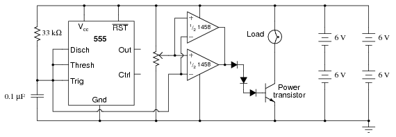
SCHEMATIC DIAGRAM
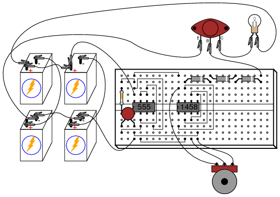
ILLUSTRATION
INSTRUCTIONS
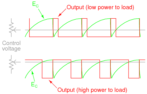
This circuit uses a 555 timer to generate a sawtooth voltage waveform across a capacitor, then compares that signal against a steady voltage provided by a potentiometer, using an op-amp as a comparator. The comparison of these two voltage signals produces a square-wave output from the op-amp, varying in duty cycle according to the potentiometer’s position. This variable duty cycle signal then drives the base of a power transistor, switching current on and off through the load. The 555’s oscillation frequency is much higher than the lamp filament’s ability to thermally cycle (heat and cool), so any variation in duty cycle, or pulse width, has the effect of controlling the total power dissipated by the load over time.
Controlling electrical power through a load by means of quickly switching it on and off, and varying the “on” time, is known as pulse-width modulation, or PWM. It is a very efficient means of controlling electrical power because the controlling element (the power transistor) dissipates comparatively little power in switching on and off, especially if compared to the wasted power dissipated of a rheostat in a similar situation. When the transistor is in cutoff, its power dissipation is zero because there is no current through it. When the transistor is saturated, its dissipation is very low because there is little voltage dropped between collector and emitter while it is conducting current.
PWM is a concept easier understood through experimentation than reading. It would be nice to view the capacitor voltage, potentiometer voltage, and op-amp output waveforms all on one (triple-trace) oscilloscope to see how they relate to one another, and to the load power. However, most of us have no access to a triple-trace oscilloscope, much less any oscilloscope at all, so an alternative method is to slow the 555 oscillator down enough that the three voltages may be compared with a simple DC voltmeter. Replace the 0.1 µF capacitor with one that is 100 µF or larger. This will slow the oscillation frequency down by a factor of at least a thousand, enabling you to measure the capacitor voltage slowly rise over time, and the op-amp output transition from “high” to “low” when the capacitor voltage becomes greater than the potentiometer voltage. With such a slow oscillation frequency, the load power will not be proportioned as before. Rather, the lamp will turn on and off at regular intervals. Feel free to experiment with other capacitor or resistor values to speed up the oscillations enough so the lamp never fully turns on or off, but is “throttled” by quick on-and-off pulsing of the transistor.
When you examine the schematic, you will notice two operational amplifiers connected in parallel. This is done to provide maximum current output to the base terminal of the power transistor. A single op-amp (one-half of a 1458 IC) may not be able to provide sufficient output current to drive the transistor into saturation, so two op-amps are used in tandem. This should only be done if the op-amps in question are overload-protected, which the 1458 series of op-amps are. Otherwise, it is possible (though unlikely) that one op-amp could turn on before the other, and damage result from the two outputs short-circuiting each other (one driving “high” and the other driving “low” simultaneously). The inherent short-circuit protection offered by the 1458 allows for direct driving of the power transistor base without any need for a current-limiting resistor.
The three diodes in series connecting the op-amps’ outputs to the transistor’s base are there to drop voltage and ensure the transistor falls into cutoff when the op-amp outputs go “low.” Because the 1458 op-amp cannot swing its output voltage all the way down to ground potential, but only to within about 2 volts of ground, a direct connection from the op-amp to the transistor would mean the transistor would never fully turn off. Adding three silicon diodes in series drops approximately 2.1 volts (0.7 volts times 3) to ensure there is minimal voltage at the transistor’s base when the op-amp outputs go “low.”
It is interesting to listen to the op-amp output signal through an audio detector as the potentiometer is adjusted through its full range of motion. Adjusting the potentiometer has no effect on signal frequency, but it greatly affects duty cycle. Note the difference in tone quality, or timbre, as the potentiometer varies the duty cycle from 0% to 50% to 100%. Varying the duty cycle has the effect of changing the harmonic content of the waveform, which makes the tone sound different.
You might notice a particular uniqueness to the sound heard through the detector headphones when the potentiometer is in the center position (50% duty cycle—50% load power), versus a kind of similarity in sound just above or below 50% duty cycle. This is due to the absence or presence of even-numbered harmonics. Any waveform that is symmetrical above and below its centerline, such as a square wave with a 50% duty cycle, contains no even-numbered harmonics, only odd-numbered. If the duty cycle is below or above 50%, the waveform will not exhibit this symmetry, and there will be even-numbered harmonics. The presence of these even-numbered harmonic frequencies can be detected by the human ear, as some of them correspond to octaves of the fundamental frequency and thus “fit” more naturally into the tone scheme.