
8.7: CMOS 555 Long Duration Flyback LED Flasher
- Page ID
- 2217

PARTS AND MATERIALS
- Two AAA Batteries
- Battery Clip (Radio Shack catalog # 270-398B)
- U1, U2 - CMOS TLC555 timer IC (Radio Shack catalog # 276-1718 or equivalent)
- Q1 - 2N3906 PNP Transistor (Radio Shack catalog #276-1604 (15 pack) or equivalent)
- Q2 - 2N2222 NPN Transistor (Radio Shack catalog #276-1617 (15 pack) or equivalent)
- D1 - Red light-emitting diode (Radio Shack catalog # 276-041 or equivalent)
- D2 - Blue light-emitting diode (Radio Shack catalog # 276-311 or equivalent)
- R1 - 1.5 MΩ 1/4W 5% Resistor
- R2 - 47 KΩ 1/4W 5% Resistor
- R3,R5 - 10 KΩ 1/4W 5% Resistor
- R4 - 1 MΩ 1/4W 5% Resisto
- r
- R6 - 100 KΩ 1/4W 5% Resistor
- R7 - 1 KΩ 1/4W 5% Resistor
- C1 - 1 µF Tantalum Capacitor (Radio Shack catalog # 272-1025 or equivalent)
- C2 - 100 pF Ceramic Disc Capacitor (Radio Shack catalog # 272-123)
- C3 - 100 µF Electrolytic Capacitor (Radio Shack catalog 272-1028 or equivalent)
- L1 - 200 µH Choke or Inductor (Exact value not critical, see end of chapter)
CROSS-REFERENCES
Lessons In Electric Circuits, Volume 1, chapter 16: Title “Inductor transient response”
Lessons In Electric Circuits, Volume 1, chapter 16: Title “Why L/R and not LR?”
Lessons In Electric Circuits, Volume 3, chapter 4: Title “The common-emitter amplifier”
Lessons In Electric Circuits, Volume 3, chapter 9: Title “Electrostatic Discharge”
Lessons In Electric Circuits, Volume 4, chapter 10: Title “Monostable multivibrators”
LEARNING OBJECTIVES
- Learn another mode of operation for the 555
- How to handle ESD Parts
- How to use a transistor for a simple gate (resistor transistor inverter)
- How inductors can convert power using inductive flyback
- How to make an inductor
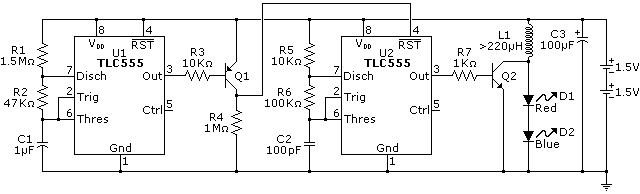
SCHEMATIC DIAGRAM
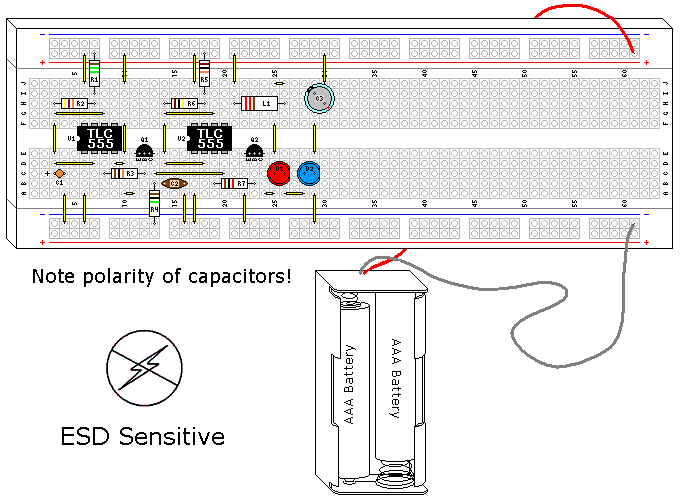
ILLUSTRATION
INSTRUCTIONS
NOTE! This project uses a static sensitive part, the CMOS 555. If you do not use protection as described in Volume 3, Chapter 9, ElectroStatic Discharge, you run the risk of destroying it.
This particular experiment builds on another experiment, “Commutating diode” (Volume 6, chapter 5). It is worth reviewing that section before proceeding.
This is the last of the long duration LED flasher series. They have shown how to use a CMOS 555 to flash an LED, and how to boost the voltage of the batteries to allow an LED with more voltage drop than the batteries to be used. Here we are doing the same thing, but with an inductor instead of a capacitor.
The basic concept is adapted from another invention, the Joule Thief. A joule thief is a simple transistor oscillator that also uses inductive kickback to light an white light LED from a 11/2 battery, and the LED needs at least 3.6 volts to start conducting! Like the joule thief, it is possible to use 11/2 volts to get this circuit to work. However, since a CMOS 555 is rated for 2 volts minimum 11/2 volts is not recommended, but we can take advantage of the extreme efficiency of this circuit. If you want to learn more about the joule thief plenty of information can be found on the web.
This circuit can also drive more that 1 or 2 LEDs in series. As the numbers of LEDs go up the ability of the batteries to last a long duration goes down, as the amount of voltage the inductor can generate is somewhat dependent on battery voltage. For the purposes of this experiment two dissimilar LEDs were used to demonstrate its independence of LED voltage drop. The high intensity of the blue LED swamps the red LED, but if you look closely you will find the red LED is at its maximum brightness. You can use pretty much whatever color of LEDs you choose for this experiment.
Generally the high voltage created by inductive kickback is something to be eliminated. This circuit uses it, but if you make a mistake with the polarity of the LEDs the blue LED, which is more ESD sensitive, will likely die (this has been verified). An uncontrolled pulse from a coil resembles an ESD event. The transistor and the TLC555 can also be at risk.
The inductor in this circuit is probably the least critical part in the design. The term inductor is generic, you can also find this component called a choke or a coil. A solenoid coil would also work, since that is also a type of inductor. So would the coil from a relay. Of all the components I have used, this is probably the least critical I’ve come across. Indeed, coils are probably the most practical component you can make yourself that exists. I’ll cover how to make a coil that will work in this design after the Theory of Operation, but the part shown on the illustration is a 200µH choke I bought from a local electronics retailer.
THEORY OF OPERATION
Both capacitors and inductors store energy. Capacitors try to maintain constant voltage, whereas inductors try to maintain constant current. Both resist change to their respective aspect. This is the basis for the flyback transformer, which is a common circuit used in old CRT circuits and other uses where high voltage is needed with a minimum of fuss. When you charge a coil a magnetic field expands around it, basically it is an electromagnet, and the magnetic field is stored energy. When the current stops this magnetic field collapses, created electricity as the field crosses the wires in the coil.
This circuit uses two astable multivibrators. The first multivibrator controls the second. Both are designed for minimum current, as well as the inverter made using Q1. Both the oscillators are very similar, the first has been covered in previous experiments. The problem is it stays on, or is high, 97% of the time. On the previous circuits we used the low state to light the LED, in this case the high is what turns the second multivibrator on. Using a simple transistor inverter designed for extra low current solves this problem. This is actually a very old logic family, RTL, which is short for resistor transistor logic.
The second multivibrator oscillates at 68.6 KHz, with a square wave that is around 50%. This circuit uses the exact same principals as is shown in the Minimum Parts LED Flasher. Again, the largest practical resistors are used to minimize current, and this means a really small capacitor for C2. This high frequency square wave is used to turn Q2 on and off as a simple switch.
Figure 1 shows what happens when the Q2 is conducting, and the coil starts to charge. If Q2 were to stay on then an effective short across the batteries would result, but since this is part of an oscillator this won’t happen. Before the coil can reach it’s maximum current Q2 switches, and the switch is open.
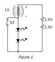
Figure 2 shows Q2 when it opens, and the coil is charged. The coil tries to maintain the current, but if there is no discharge path it can not do this. If there were no discharge path is the coil would create a high voltage pulse, seeking to maintain the current that was flowing through it, and this voltage would be quite high. However, we have a couple of LEDs in the discharge path, so the coils pulse quickly goes to the voltage drop of the combined LEDs, then dumps the rest of its charge as current. As a result there is no high voltage generated, but there is a conversion to the voltage required to light the LEDs.

The LEDs are pulsed, and the light curve follows the discharge curve of the coil fairly closely. However, the human eye averages this light output to something we perceive as continuous light.
PARTS AND MATERIALS
- 26 Feet (8 Meters) of 26AWG Magnet Wire (Radio Shack catalog #278-1345 or equivalent)
- 6/32X1.5 inch screw, a M4X30mm screw, or a nail of similar diameter cut down to size, steel or iron, but not stainless
- Matching lock nut (optional)
- Transparent Tape (optional, needed if using screws)
- Super Glue
- Soldering Iron, Solder
As has been mentioned before, this is not a precision part. Inductors in general can have a large variance for many applications, and this one specifically can be off on the high side a large amount. The target here is greater than 220µH.
If you are using a screw, use one layer of the transparent tape between the threads and the wire. This is to prevent the threads of the screw from cutting into the wire and shorting the coil out. If you are using a lock nut put it on the screw 1” (25mm) from the head of the screw. Starting around 1” from one end of the wire, use the glue to tack the wire on the head of the nail or screw as shown. Let the glue set.
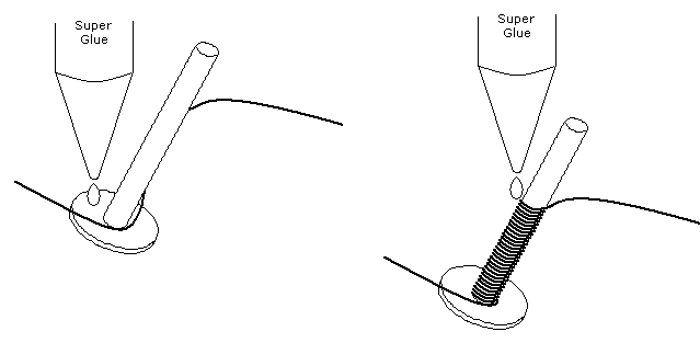
Wind the wire neatly and tightly 1” the length of screw, again tacking it in place with super glue. (Figure above). You can use a variable speed drill to help with this, as long as you are careful. Like all power appliances, it can bite you. Hold the wire tight until the glue sets, then start winding a second layer over the first. Continue this process until all of the wire except the last 1” is used, using the glue to occasionally tack the wire down. Arrange the wire on the last layer so the second inductor lead is on the other end of the screw away from the first. Tack this down for a final time with the glue. Let dry completely.
Gently take a sharp blade and scrap the enamel off each end of the two leads. Tin the exposed copper with the soldering iron and the solder, and you now have a functional inductor that can be used in this experiment.
Here is what the one I made looked like: Figure below.
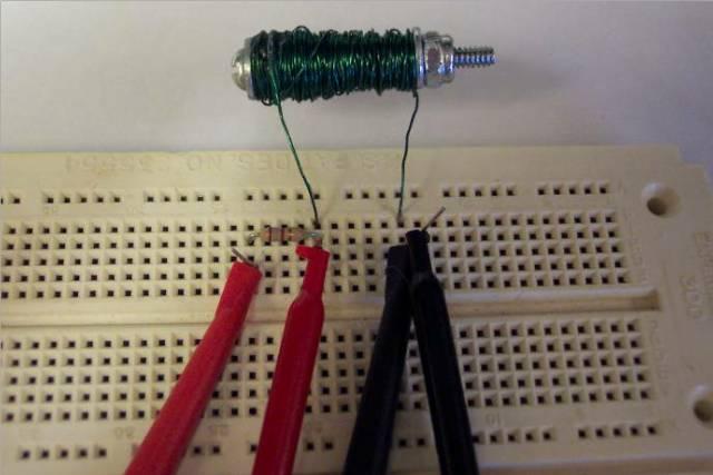
The connections shown are being used to measure the inductance, which worked out pretty close to 220µH.