
2.4: Principles of Dimensioning
- Page ID
- 3232
A good sketch of an object is one that you can use as a blueprint to manufacture the object. Your sketch must show all the necessary dimensions of the part, locate any features it may have (such as holes and slots), give information on the material it is to be made from, and if necessary, stipulate the processes to be used in the manufacture of the object.
Three principles of dimensioning must be followed:
- Do not leave any size, shape, or material in doubt.
- To avoid confusion and the possibility of error, no dimension should be repeated twice on any sketch or drawing.
- Dimensions and notations must be placed on the sketch where they can be clearly and easily read.
Consider Figure \(\PageIndex{1}\) and note whether these three dimensioning principles have been followed.
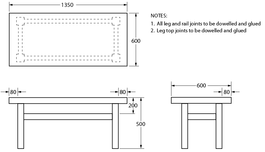
Figure \(\PageIndex{1}\): Shop table
Although the dimensions and notations are clear and easy to read in Figure 14, the following points should be made:
- Leg and rail sizes have not been shown.
- The thickness of the top has not been given.
- The material has not been given as a notation.
- The 600 dimension has been repeated.
- The type of finish to be used has not been given.
- Note 2 is redundant.
The sketch of the shop table is far from complete, and the table could not be made without a lot of guesswork. Figure \(\PageIndex{2}\), on the other hand, shows a completed sketch that, along with the necessary notes and dimension information, can be readily used for construction purposes.
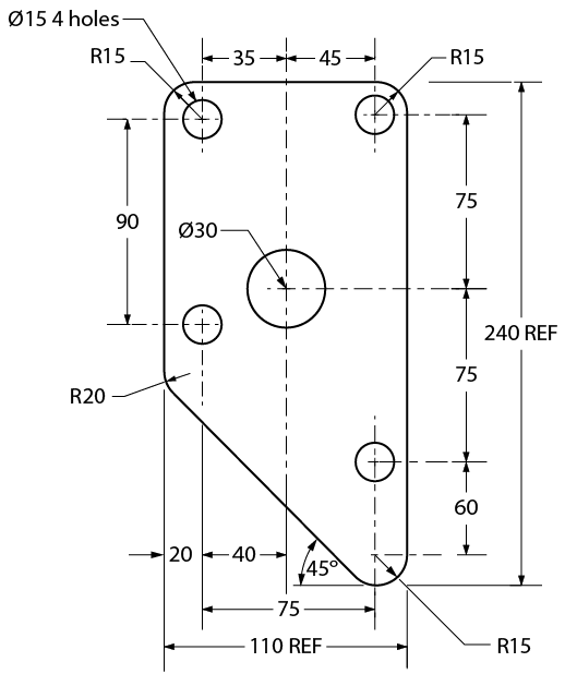
Figure \(\PageIndex{2}\): Dimensioning
Rules of dimensioning
For most objects, there are three types of dimensions:
- size dimensions
- location dimensions
- notation dimensions
Figure \(\PageIndex{3}\) illustrates the difference between size and location dimensions. (S = size dimension and L = location dimension).
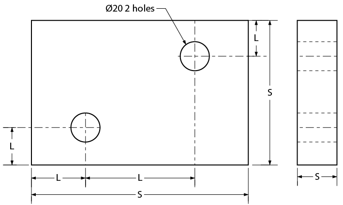
Figure \(\PageIndex{3}\): Shim Plate
Size dimensions are necessary so that the material size of the object can be determined. Location dimensions are necessary so that parts, holes, or other features can be positioned in or on the object. Notation dimensions describe the part, hole, or other feature with a short note, such as the “ø20 2 holes” notation (see Figure 16). Keep these points in mind:
- Keep all dimension lines at least 10 mm (3/8") clear of object lines wherever possible.
- Try to group related dimensions rather than scattering them.
- Try to keep dimensions off the views themselves.
- Separate one line of dimensions from another line of dimensions or from a notation by a space of at least 10 mm (3/8").
- Leave a space of approximately 3 mm (1/8") between the object outline and the beginning of any extension line.
- Keep arrowheads slim and neat.
- Never dimension to a hidden line.
- Draw leader lines at an angle when intersecting object lines to avoid confusing them with extension lines.
Figure \(\PageIndex{4}\) illustrates good placement of dimensions and notations. Note the placement of extension lines and the use of center lines to locate features such as holes. Also, note the shape and size of arrowheads.
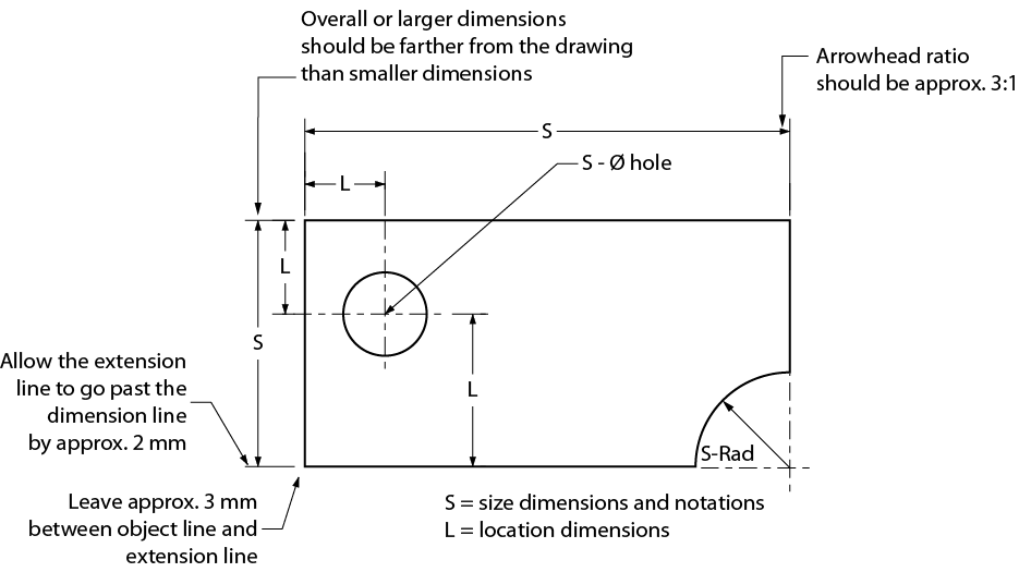
Figure \(\PageIndex{4}\): Extension line usage
Dimensioning systems
Two systems are used for dimensioning drawings. They are aligned and unidirectional systems. Figure \(\PageIndex{5}\) shows examples of both systems. As you can see, the aligned system requires that you turn the drawing on its side, whereas the unidirectional system may be read from the normal reading position. For most drawings, the unidirectional system is preferred, as it is easier to read; however, architectural drawings still use the aligned system.
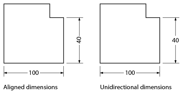
Figure \(\PageIndex{5}\): Dimensioning systems
Systems of measurement
You may be required to sketch or read drawings constructed with either metric (SI) or imperial dimensions. You may also encounter drawings that are dual-dimensioned and contain both systems of measurement on the same drawing.
SI system of measurement
The SI system of measurement has become the official standard in Canada. It is common practice on shop drawings to express all metric dimensions in millimeters. Figure \(\PageIndex{6}\) shows a detail drawing of a connector arm using metric measurements. All metric drawings should contain a note specifying that all dimensions are in millimeters.
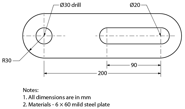
Figure \(\PageIndex{6}\): Connector arm – metric measurement
Imperial system of measurement
An imperial drawing may use the decimal-inch system, the fractional-inch system, or feet and
inches.
- In the decimal-inch system, very accurate dimensions for items such as machine parts are expressed as decimals of an inch, such as 0.005". In words, this reads as five one-thousandths of an inch.
- In the fraction-inch system, dimensions for things such as steel and lumber sizes are expressed as inches and fractions of an inch from as small as 1/64" (Figure \(\PageIndex{7}\)). Most drawings that are dimensioned in the imperial system will use the fraction-inch system.
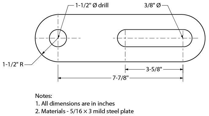
Figure \(\PageIndex{7}\): Connector arm – imperial measurement
In the feet-inch system (Figure \(\PageIndex{8}\)), the dimensions of large structures such as machine frames and buildings are expressed in feet and inches, such as 2'-6" (two feet, six inches).
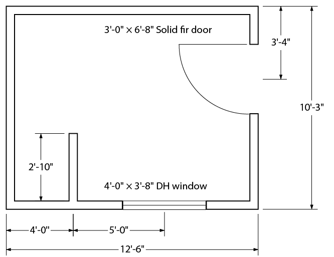
Figure \(\PageIndex{8}\): Fuel storage shed
Dimensioning orthographic sketches
The following are rules and procedures for dimensioning single- and multi-view sketches:
- Place dimensions on views that show parts of features as solid outlines. Avoid dimensioning hidden lines wherever possible.
- Try to keep dimensions between views. Leave adequate room between views when you begin your sketch.
- Keep the smallest dimensions nearest to the object outline.
- Diameters in metric measurement should be denoted on a sketch using the symbol ø (e.g., ø20 – 2 holes). A radius should be denoted using the letter R (e.g., R 25).
- Diameters in imperial measurements may be denoted on a sketch by the symbol ø or the abbreviation DIA (e.g., 3" ø DRILL or 4½" DIA). A radius may be denoted using the letter R or the abbreviation RAD (e.g., 3" R or 6½" RAD).
- Arrows carrying notations should always point toward the center of circular objects.
- Arrows should always point toward a circle center when dimensioning a diameter and away from the center when dimensioning a radius.