
1.5: Unit 4: Offset Boring Head
- Page ID
- 2272
OBJECTIVE
After completing this unit, you should be able to:
- Identify offset Boring head
- Explain how to correct set up for Rotary Table.
Offset Boring Head
The offset boring is an attachment that fits the milling machine spindle and permits most drilled holes to have a better finish and greater diameter accuracy. Offset boring head are used to create large hole when tolerance do not allow for a drill bit or do not have a large enough drill or reamer. A offset boring head can be used to enlarge hole, or adjust hole centerline in certain instances.
Safety:
Be sure all set screws are tight before operation. Be sure offset boring head has a clearance to fit into hole when boring. Remove Allen wrench before turning the mill one. Double check mill speed before operation.
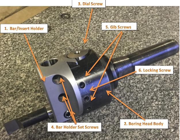
Figure 1. Offset Boring Head
OFFSET BORING HEAD AND TOOLS
Figure 1. shows an offset boring head. Note that the boring bar can be adjusted at a right angle axis. This feature makes it possible to position the boring cutter accurately to bore holes of varying diameters.
This adjustment is more convenient than adjusting the cutter in the boring bar holder or changing the boring bar. Another advantage of the offset boring head is the fact that graduated micrometer collar allows the tool to be moved accurately a specified amount usually in increments of (0.001) without the use of dial indicator or other measuring device.
Offset Boring Head
A Boring Heads have three major components:
- boring head body
- bar holder/insert holder
- dial screw
The boring head body has a black oxide finish for rust prevention. The bar holder or insert holder (#1) has been satin chromed for wear resistance. The dial screw (#3) has been precision ground to give accurate movement of the bar holder/insert holder in the dove tail slide. The gib tension has been preset at the factory. The two gib screws (#5) should not be loosened to make size adjustments. These screws are for adjusting the gib pressure only and are filled with red wax to prevent accidental adjustment. The locking screw (#6) is the only screw used for making size changes to the boring head.
Diameter Adjustment
To adjust the diameter of an Allied Criterion standard boring head:
1. Loosen the locking screw (#6).
2. Turn the dial screw (#3) clockwise to increase the diameter and counterclockwise to decrease the diameter.
3. Tighten the locking screw (#6). Adjusting Standard Boring Heads
Procedure:
- Set up and carefully align the work parallel to the table travel.
2. Align the center of the Milling Machine spindle with the reference point on the work.
3. Spot the location of hole with a center drill or spotting tool.
4. Drilled hole over ½ inch, Be sure offset boring head has a clearance to fit into hole when boring.
5. Install bore head into Milling Machine.
6. Install boring bar and tighten set screw and loosen lock screw and adjust boring bar to hole edge.
7. Recheck the work alignment, as well as the alignment of the spindle with the reference point, to make sure it has not shifted. If any error is evident, it will necessary to repeat procedure 6 before processing.
8. Adjust Milling Machine speed for hole size and material.
9. Engage worm feed on Mill. Bring quill to material. Pull handle out to engage power feed. When at desired depth push hand back to disengage feed and then turn off Mill. Remove boring head from hole.
10. Finish bore hole to the required size.
NOTE: Repeat Procedures 6-9 until hole is desired size.
Rotary Table
A rotary table can be used to make arcs and circles. For example, the circular T-slot in the swivel base for a vise can be made using a rotary table. Rotary tables can also be used for indexing, where a workpiece must be rotated an exact amount between operations. You can make gears on a milling machine using a rotary table. Dividing plates make indexing with a rotary table easier.
Rotary tables are most commonly mounted “flat”, with the table rotating around a vertical axis, in the same plane as the cutter of a vertical milling machine. An alternate setup is to mount the rotary table on its end (or mount it “flat” on a 90° angle plate), so that it rotates about a horizontal axis. In this configuration a tailstock can also be used, thus holding the workpiece “between centers.”
With the table mounted on a secondary table, the workpiece is accurately centered on the rotary table’s axis, which in turn is centered on the cutting tool’s axis. All three axes are thus coaxial. From this point, the secondary table can be offset in either the X or Y direction to set the cutter the desired distance from the workpiece’s center. This allows concentric machining operations on the workpiece. Placing the workpiece eccentrically a set distance from the center permits more complex curves to be cut. As with other setups on a vertical mill, the milling operation can be either drilling a series of concentric, and possibly equidistant holes, or face or end milling either circular or semicircular shapes and contours.
A rotary table can be used:
- To machine spanner flats on a bolt
- To drill equidistant holes on a circular flange
- To cut a round piece with a protruding tang
- To create large-diameter holes, via milling in a circular toolpath, on small milling machines that don’t have the power to drive large twist drills (>0.500″/>13 mm)
- To mill helixes
- To cut complex curves (with proper setup)
- To cut straight lines at any angle
- To cut arcs
- With the addition of a compound table on top of the rotary table, the user can move the center of rotation to anywhere on the part being cut. This enables an arc to be cut at any place on the part.
- To cut circular pieces
Setting Up a Rotary Table
When using a rotary table on a Milling Machine, whether to mill an arc or drill holes in some circular pattern, there are two things that must be done to set up the workpiece. First, the workpiece must be centered on the rotary table. Second, the rotary table must be centered under the spindle. Then the mill table can be moved some appropriate distance and you can start cutting.
You could center the table under the spindle first, by indicating off the hole in the center of the table. Then you could mount the workpiece on the table and indicate off the workpiece. There are two problems with this approach. First, you are assuming that the hole in the table is true and centered. That may or may not be true. Second, this approach risks a sort of accumulation of errors, as you’re measuring from two different features (the rotary table’s hole and some feature on the workpiece). First center the workpiece on the rotary table, and then center the rotary table under the spindle.
To center the workpiece on the rotary table, spin the rotary table and watch for deflection of the indicator pointer. Adjust the position of the mill table(X and Y) as required, until the needle no longer deflects.
You dial in a rotary table by placing a dial test indicator in a chuck or collet in the spindle, which is then rotated by hand with the indicator tip in contact with the hole of the rotary table. If your machine can be taken out of gear, it helps to do so, so the spindle swings freely. It’s obviously easier to use a drill chuck than a collet, too, so you have something that you can turn easily. Make your adjustments using the saddle and table hand wheels.
Once you have center located (the indicator will read the same as you rotate the spindle, it’s a very good idea to set both of your dials at “0”, instead of marking some random location. Make sure you have backlash set properly, too. Set the dial is reading in a positive direction so it’s easy to count off any changes, and you never have to remember which way you had chosen to set backlash. I also always mark the table and saddle with a wax pencil so I know where center is located. That tells you when to stop turning the handle when “0” comes around if you want to get the table back to center to load another part.
Once you have located center of the table and have set dials and locked the table and saddle, you usually have some feature on your part that you desire to be centered. In some cases it may be a hole, in others it may be the outside edge of the circular part. In a case like either of these, it’s common practice to use the same indicator and swing it inside the hole or the perimeter of the part. The perimeter may require you to get around clamps, which can usually be accomplished by using the quill to move the indicator up far enough to clear them. When you dial in parts to a table that has already been located, you tap the part around, you do not make adjustments with the saddle or table handles. Tap the part after you’ve snugged up the clamps slightly, so it doesn’t move about wildly. You can achieve virtually perfect location that way, certainly as close as the machine is capable of working.
After the workpiece is centered on the rotary table, you now turn the spindle by hand, so the indicator tip sweeps the inside of the hole. Adjust the position of the mill table as required until no needle deflection is noted.
Setting up your Rotary Table
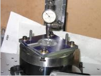
How to center the spindle over the center of the rotary table. Here are some of the methods to use.
To Center the Rotary Table with the Vertical Mill Spindle
Follow The following procedure:
1. Square the vertical head with the machine table.
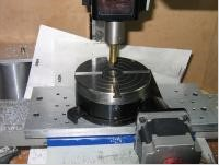
2. Mount the rotary table on the milling machine table.
3. Place a test plug in the center hole of the rotary table.
4. Mount an dial indicator in the milling machine spindle.
5. With the dial indicator just clearing the top of the test plug, rotate the machine spindle by hand and approximately align the plug with the spindle.
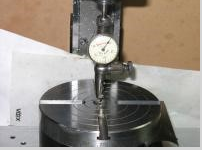
6. Bring the dial indicator into contact with the diameter of the plug, and rotate the spindle by hand.
7. Adjust the machine table by the longitudinal(X) and crossfeed(Y) handles until the dial indicator registers no movement.
8. Lock the milling machine table and saddle, and recheck the alignment.
9. Readjust if necessary.
A way to setup your rotary table
 |
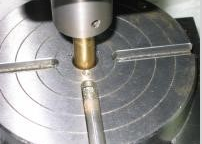

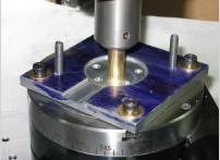


Indicate Jig

Centering the jig or workpiece over the center of the rotary table. To do this, rotate the rotary table and adjust the work piece until I get consistent run out all the way around.
To Center a Workpiece with the Rotary Table
Often it is necessary to perform a rotary table operation on several identical workpieces, each having a machined hole in the center. To quickly align each workpiece, a special plug can be made to fit the center hole of the workpiece and the hole in the rotary table. Once the machine spindle has been aligned with the rotary table, each succeeding piece can be aligned quickly and accurately by placing it over the plug.
If there are only a few pieces, which would not justify the manufacture of a special plug, or if the workpiece does not have a hole through it center, the following method can be used to center the workpiece on the rotary table.
1. Align the rotary table with the vertical mill head spindle.
2. Lightly clamp the workpiece on the rotary table in the center. Do not move the longitudinal(X) or crossfeed(Y) feed handles.
3. Disengage the rotary table worm mechanism.
4. Mount an dial indicator in the milling machine spindle or milling machine table, depending upon the workpiece.
5. Bring the dial indicator into contact with the surface to be indicated, and revolve the rotary table by hand.
6. With a soft metal bar, tap the workpiece(away from the indicator movement) until no movement is registered on the indicator in a complete revolution of the rotary table.
7. Clamp the workpiece tightly, and recheck the accuracy of the setup.
Radius Milling
To mill the end on the workpiece to a certain radius or to machine circular slots having a definite radius, following procedure below should be followed.
1. Align the vertical milling machine at 90* to the table.
2. Mount an dial indicator in the milling machine spindle.
3. Mount rotary table on the milling machine table.
4. Center the rotary table with the machine spindle using a test plug in the table and a dial indicator on the spindle.
5. Set the longitudinal(X)feed dial and the crossfeed(Y) dial to zero.
6. Mount the workpiece on the rotary table, aligning the center of the radial cuts with the center of the table. A special arbor may be used for this. Another method is to align the center of the radial cut with a wiggler mounted in the machine spindle.
7. Move either the crossfeed or the longitudinal feed(whichever is more convenient) an amount equal to the radius required.
8. Lock both the table and the saddle.
9. Mount the proper end mill.
10. Set the correct speed(RPM).
11. Rotate the workpiece, using the rotary table feed handwheel, to the starting point of the cut.
12. Set the depth of the cut and machine the radius to the size indicated on the drawing, using hand or power feed.
UNIT TEST
1. When is an offset boring head used?
2. Name three major components of Boring Heads.
3. Why is the locking screw tightened after tool slide adjustments have been made.
4. Why does the tool slide have multiple holes to hold boring tools?
5. What determines the cutting speed in boring?
6. For what purpose may a rotary table be used?
7. What is the purpose of the hole in the center of a rotary table?
8. Describe briefly how a rotary table may be centered with a vertical mill spindle.
9. Describe briefly how a single workpiece would be centered on a rotary table.
10. Explain how a large radius may be cut using a rotary table.
Chapter Attribution Information
This chapter was derived from the following sources.
- Tapping Procedures derived from Drilling and Tapping by the University of Idaho, CC:BY-SA 3.0.
- Tramming derived from Tramming Mill Head by the University of Idaho, CC:BY-SA 3.0.
- Dial Indicator (Photo) derived from Dial Gauge by Wikimedia, CC:BY-SA 3.0.
- Milling Machine Procedures derived from Mechanical Engineering Tools by the Massachusetts Institute of Technology, CC:BY-NC-SA 4.0.
- Rotary Table derived from Rotary Table by the University of Idaho, CC:BY-SA 3.0.