
4.10: Induction Motor, Large
- Page ID
- 2161

\( \newcommand{\vecs}[1]{\overset { \scriptstyle \rightharpoonup} {\mathbf{#1}} } \)
\( \newcommand{\vecd}[1]{\overset{-\!-\!\rightharpoonup}{\vphantom{a}\smash {#1}}} \)
\( \newcommand{\dsum}{\displaystyle\sum\limits} \)
\( \newcommand{\dint}{\displaystyle\int\limits} \)
\( \newcommand{\dlim}{\displaystyle\lim\limits} \)
\( \newcommand{\id}{\mathrm{id}}\) \( \newcommand{\Span}{\mathrm{span}}\)
( \newcommand{\kernel}{\mathrm{null}\,}\) \( \newcommand{\range}{\mathrm{range}\,}\)
\( \newcommand{\RealPart}{\mathrm{Re}}\) \( \newcommand{\ImaginaryPart}{\mathrm{Im}}\)
\( \newcommand{\Argument}{\mathrm{Arg}}\) \( \newcommand{\norm}[1]{\| #1 \|}\)
\( \newcommand{\inner}[2]{\langle #1, #2 \rangle}\)
\( \newcommand{\Span}{\mathrm{span}}\)
\( \newcommand{\id}{\mathrm{id}}\)
\( \newcommand{\Span}{\mathrm{span}}\)
\( \newcommand{\kernel}{\mathrm{null}\,}\)
\( \newcommand{\range}{\mathrm{range}\,}\)
\( \newcommand{\RealPart}{\mathrm{Re}}\)
\( \newcommand{\ImaginaryPart}{\mathrm{Im}}\)
\( \newcommand{\Argument}{\mathrm{Arg}}\)
\( \newcommand{\norm}[1]{\| #1 \|}\)
\( \newcommand{\inner}[2]{\langle #1, #2 \rangle}\)
\( \newcommand{\Span}{\mathrm{span}}\) \( \newcommand{\AA}{\unicode[.8,0]{x212B}}\)
\( \newcommand{\vectorA}[1]{\vec{#1}} % arrow\)
\( \newcommand{\vectorAt}[1]{\vec{\text{#1}}} % arrow\)
\( \newcommand{\vectorB}[1]{\overset { \scriptstyle \rightharpoonup} {\mathbf{#1}} } \)
\( \newcommand{\vectorC}[1]{\textbf{#1}} \)
\( \newcommand{\vectorD}[1]{\overrightarrow{#1}} \)
\( \newcommand{\vectorDt}[1]{\overrightarrow{\text{#1}}} \)
\( \newcommand{\vectE}[1]{\overset{-\!-\!\rightharpoonup}{\vphantom{a}\smash{\mathbf {#1}}}} \)
\( \newcommand{\vecs}[1]{\overset { \scriptstyle \rightharpoonup} {\mathbf{#1}} } \)
\(\newcommand{\longvect}{\overrightarrow}\)
\( \newcommand{\vecd}[1]{\overset{-\!-\!\rightharpoonup}{\vphantom{a}\smash {#1}}} \)
\(\newcommand{\avec}{\mathbf a}\) \(\newcommand{\bvec}{\mathbf b}\) \(\newcommand{\cvec}{\mathbf c}\) \(\newcommand{\dvec}{\mathbf d}\) \(\newcommand{\dtil}{\widetilde{\mathbf d}}\) \(\newcommand{\evec}{\mathbf e}\) \(\newcommand{\fvec}{\mathbf f}\) \(\newcommand{\nvec}{\mathbf n}\) \(\newcommand{\pvec}{\mathbf p}\) \(\newcommand{\qvec}{\mathbf q}\) \(\newcommand{\svec}{\mathbf s}\) \(\newcommand{\tvec}{\mathbf t}\) \(\newcommand{\uvec}{\mathbf u}\) \(\newcommand{\vvec}{\mathbf v}\) \(\newcommand{\wvec}{\mathbf w}\) \(\newcommand{\xvec}{\mathbf x}\) \(\newcommand{\yvec}{\mathbf y}\) \(\newcommand{\zvec}{\mathbf z}\) \(\newcommand{\rvec}{\mathbf r}\) \(\newcommand{\mvec}{\mathbf m}\) \(\newcommand{\zerovec}{\mathbf 0}\) \(\newcommand{\onevec}{\mathbf 1}\) \(\newcommand{\real}{\mathbb R}\) \(\newcommand{\twovec}[2]{\left[\begin{array}{r}#1 \\ #2 \end{array}\right]}\) \(\newcommand{\ctwovec}[2]{\left[\begin{array}{c}#1 \\ #2 \end{array}\right]}\) \(\newcommand{\threevec}[3]{\left[\begin{array}{r}#1 \\ #2 \\ #3 \end{array}\right]}\) \(\newcommand{\cthreevec}[3]{\left[\begin{array}{c}#1 \\ #2 \\ #3 \end{array}\right]}\) \(\newcommand{\fourvec}[4]{\left[\begin{array}{r}#1 \\ #2 \\ #3 \\ #4 \end{array}\right]}\) \(\newcommand{\cfourvec}[4]{\left[\begin{array}{c}#1 \\ #2 \\ #3 \\ #4 \end{array}\right]}\) \(\newcommand{\fivevec}[5]{\left[\begin{array}{r}#1 \\ #2 \\ #3 \\ #4 \\ #5 \\ \end{array}\right]}\) \(\newcommand{\cfivevec}[5]{\left[\begin{array}{c}#1 \\ #2 \\ #3 \\ #4 \\ #5 \\ \end{array}\right]}\) \(\newcommand{\mattwo}[4]{\left[\begin{array}{rr}#1 \amp #2 \\ #3 \amp #4 \\ \end{array}\right]}\) \(\newcommand{\laspan}[1]{\text{Span}\{#1\}}\) \(\newcommand{\bcal}{\cal B}\) \(\newcommand{\ccal}{\cal C}\) \(\newcommand{\scal}{\cal S}\) \(\newcommand{\wcal}{\cal W}\) \(\newcommand{\ecal}{\cal E}\) \(\newcommand{\coords}[2]{\left\{#1\right\}_{#2}}\) \(\newcommand{\gray}[1]{\color{gray}{#1}}\) \(\newcommand{\lgray}[1]{\color{lightgray}{#1}}\) \(\newcommand{\rank}{\operatorname{rank}}\) \(\newcommand{\row}{\text{Row}}\) \(\newcommand{\col}{\text{Col}}\) \(\renewcommand{\row}{\text{Row}}\) \(\newcommand{\nul}{\text{Nul}}\) \(\newcommand{\var}{\text{Var}}\) \(\newcommand{\corr}{\text{corr}}\) \(\newcommand{\len}[1]{\left|#1\right|}\) \(\newcommand{\bbar}{\overline{\bvec}}\) \(\newcommand{\bhat}{\widehat{\bvec}}\) \(\newcommand{\bperp}{\bvec^\perp}\) \(\newcommand{\xhat}{\widehat{\xvec}}\) \(\newcommand{\vhat}{\widehat{\vvec}}\) \(\newcommand{\uhat}{\widehat{\uvec}}\) \(\newcommand{\what}{\widehat{\wvec}}\) \(\newcommand{\Sighat}{\widehat{\Sigma}}\) \(\newcommand{\lt}{<}\) \(\newcommand{\gt}{>}\) \(\newcommand{\amp}{&}\) \(\definecolor{fillinmathshade}{gray}{0.9}\)PARTS AND MATERIALS
- AC power source: 120VAC
- Capacitor, 3.3 µF 120VAC or 350VDC, non-polarized
- #33 AWG magnet wire, 2 pounds
- wooden board approx. 6 to 12 in. square.
- AC line cord with plug
- 5.1-inch dia. plastic 3-liter soda bottle
- discarded ballpoint pen
- misc. small wood blocks
CROSS-REFERENCES
Lessons In Electric Circuits, Volume 2, chapter 13: “AC motors”, “Single Phase induction motors”,“Permanent split-capacitor motor”.
LEARNING OBJECTIVES
- To build a large exhibit size AC permanent split-capacitor induction motor.
- To illustrate the simplicity of the AC induction motor.
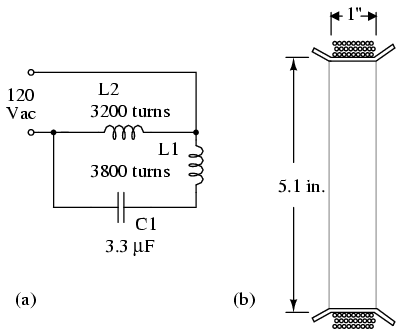
SCHEMATIC DIAGRAM
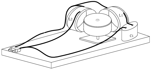
ILLUSTRATION
INSTRUCTIONS
This is a larger version of a “permanent capacitor split-phase induction motor”. There are two different stator coils. The 1.0 inch wide 3200 turn L2 winding is shown in the illustration above (b), wound over a section of 5.1-inch diameter plastic 3-liter soda bottle. L1 is approximately 3800 turns of #33 AWG (American wire gauge) enameled magnet wire wound over a 1.25 width of a section of a soda bottle, wider than shown at (b). Mark a 1.25-inch wide cylinder with 0.25-inch margins on each end. The wire will be wound on the 1.25-inch zone. The form is cut from the bottle on the outside edges of the margin. Cuts of 0.25 inch from the margin to the winding zone are spaced at 1-inch intervals around the circumference of both ends so that the margin may be bent up at 90o to hold the wire on the form. To avoid counting the 3800 turns, scramble wind a 1/8 inch thickness of magnet wire over the one-inch width of the form. Else, count the turns. Scrape the enamel from 1-inch on the free end, and scrape only a small section from the lead to the spool. Do NOT cut the lead to the spool. Measure the resistance, and estimate how much more wire to wind to achieve 894 Ω. Apply enamel, nail polish, tape, or other insulation to the bare spot on the spool lead. Continue winding, and recheck the resistance. Once the approximate 894 Ω is achieved, leave a few inches of magnet wire for the lead. Cut the lead from the spool. Secure the windings to the form with lacing twine or other means.
The L1 winding of 3200 turns is approximately 744 Ω and is wound on a 1.0-inch wide form as shown at (b) in a manner similar to the previous L2 winding.
Strip the enamel off 1-inch of the ends of magnet wire leads if not already done. Splice the bare ends to heavier gauge insulated hook-up wire. Solder the splice. Insulate with tape or heat-shrink tubing. Secure the splice to the coil body. Then proceed with the second coil. The coils may be mounted in one corner of the wooden base. Alternatively, for more flexibility in use, they may be mounted to movable pallets.
Refer to both the schematic diagram and the illustration for assembly. Note that the coils are mounted at right angles. L2, the smaller coil is wired to both sides of the 120 Vac line. The capacitor is wired in series with the wider coil L1. The capacitor provides a leading phase shift of the current with respect to voltage. The schematic and illustration show no power switch or fuse. Add these additions are recommended.
If this device is intended for use by non-technicians as an unsupervised exhibit, all exposed bare terminations like the capacitor must be made finger safe by covering with shields. The switch and fuse mentioned above are necessary. Finally, the enamel on the coils only provides a single layer of insulation. For safety, a second layer such as an insulating wrapping, Plexiglas box, or other means is called for. Replace all wooden components with Plexiglas for superior fire safety in an unsupervised exhibit.
The rotor must be made of a ferromagnetic material like a steel vegetable can, fruitcake can, etc. A too long vegetable can may be cut in half. The illustration for the previous small induction motor shows rotor dimpled bearing and pivot details. The rotor may be smaller than the coil forms as in the case of a cut down the vegetable can. It can even be as small as the can lid rotor used with the previous small motor. It is also possible to drive a rotor larger than the coils, which is the case with the fruitcake can. Locate and mark the center of the rotor. The center needs to be dimpled. Select an eighth-inch diameter (a few mm) nail (a) and file or grind the point round. Use this and a block of wood to dimple the rotor as shown in the previous small motor A fairly long can balances better than a flat rotor due to the lower center of gravity. The tip of a ballpoint pen works well as a pivot for larger rotors. Mount the pivot to a movable wooden pedestal.
Double check the wiring. Check that any bare wire has been insulated. The circuit may be powered-up without the rotor. Excessive heating in L2 indicates that more turns are required. Excessive heat in L1 calls for a reduction in the capacitance of C1. No heat at all indicates an open circuit to the affected coil.
Place the rotor atop the pivot and move it between both energized coils. It should spin. The closer it is, the faster it should spin. Both coils should be warm, indicating power. Try different size and style rotors. Try a small rotor on the opposite side of the coils compared to the illustration.
Three models of this motor have been built using #33 AWG magnet wire because a large spool was on hand. AWG #32 magnet wire is probably easier to get. It should work. Although the current will be higher due to the lower resistance of the larger diameter #32 wire. If a 3.3µF capacitor is not available, use something close as long as it has an adequate voltage rating. A discarded AC motor run capacitor (bathtub shaped) was used by the author. Do no use a motor start capacitor (black cylinder). These are only usable for a few seconds of motor starting and may explode if used longer than that.
Try this: It is possible to simultaneously spin more than one rotor. For example, in addition to the main rotor inside the right angle formed by the coils, place a second smaller rotor (can or bottle lid) near the pair of coils outside the right angle at the vertex.
It is possible to reverse the direction of rotation by reversing one of the coils. If the coils are mounted to movable pallets, rotate one coil 180o. Another method, especially useful with fixed coils, is to wire one of the coils to a DPDT polarity reversing switch. For example, disconnect L2 and wire it to the wipers (center contacts) of the DPDT switch. The top contacts go to the 120 Vac. The top contacts also go to the bottom contacts in an X-crossover pattern.