2.7: Junction Diodes
- Page ID
- 1740
\( \newcommand{\vecs}[1]{\overset { \scriptstyle \rightharpoonup} {\mathbf{#1}} } \)
\( \newcommand{\vecd}[1]{\overset{-\!-\!\rightharpoonup}{\vphantom{a}\smash {#1}}} \)
\( \newcommand{\dsum}{\displaystyle\sum\limits} \)
\( \newcommand{\dint}{\displaystyle\int\limits} \)
\( \newcommand{\dlim}{\displaystyle\lim\limits} \)
\( \newcommand{\id}{\mathrm{id}}\) \( \newcommand{\Span}{\mathrm{span}}\)
( \newcommand{\kernel}{\mathrm{null}\,}\) \( \newcommand{\range}{\mathrm{range}\,}\)
\( \newcommand{\RealPart}{\mathrm{Re}}\) \( \newcommand{\ImaginaryPart}{\mathrm{Im}}\)
\( \newcommand{\Argument}{\mathrm{Arg}}\) \( \newcommand{\norm}[1]{\| #1 \|}\)
\( \newcommand{\inner}[2]{\langle #1, #2 \rangle}\)
\( \newcommand{\Span}{\mathrm{span}}\)
\( \newcommand{\id}{\mathrm{id}}\)
\( \newcommand{\Span}{\mathrm{span}}\)
\( \newcommand{\kernel}{\mathrm{null}\,}\)
\( \newcommand{\range}{\mathrm{range}\,}\)
\( \newcommand{\RealPart}{\mathrm{Re}}\)
\( \newcommand{\ImaginaryPart}{\mathrm{Im}}\)
\( \newcommand{\Argument}{\mathrm{Arg}}\)
\( \newcommand{\norm}[1]{\| #1 \|}\)
\( \newcommand{\inner}[2]{\langle #1, #2 \rangle}\)
\( \newcommand{\Span}{\mathrm{span}}\) \( \newcommand{\AA}{\unicode[.8,0]{x212B}}\)
\( \newcommand{\vectorA}[1]{\vec{#1}} % arrow\)
\( \newcommand{\vectorAt}[1]{\vec{\text{#1}}} % arrow\)
\( \newcommand{\vectorB}[1]{\overset { \scriptstyle \rightharpoonup} {\mathbf{#1}} } \)
\( \newcommand{\vectorC}[1]{\textbf{#1}} \)
\( \newcommand{\vectorD}[1]{\overrightarrow{#1}} \)
\( \newcommand{\vectorDt}[1]{\overrightarrow{\text{#1}}} \)
\( \newcommand{\vectE}[1]{\overset{-\!-\!\rightharpoonup}{\vphantom{a}\smash{\mathbf {#1}}}} \)
\( \newcommand{\vecs}[1]{\overset { \scriptstyle \rightharpoonup} {\mathbf{#1}} } \)
\( \newcommand{\vecd}[1]{\overset{-\!-\!\rightharpoonup}{\vphantom{a}\smash {#1}}} \)
\(\newcommand{\avec}{\mathbf a}\) \(\newcommand{\bvec}{\mathbf b}\) \(\newcommand{\cvec}{\mathbf c}\) \(\newcommand{\dvec}{\mathbf d}\) \(\newcommand{\dtil}{\widetilde{\mathbf d}}\) \(\newcommand{\evec}{\mathbf e}\) \(\newcommand{\fvec}{\mathbf f}\) \(\newcommand{\nvec}{\mathbf n}\) \(\newcommand{\pvec}{\mathbf p}\) \(\newcommand{\qvec}{\mathbf q}\) \(\newcommand{\svec}{\mathbf s}\) \(\newcommand{\tvec}{\mathbf t}\) \(\newcommand{\uvec}{\mathbf u}\) \(\newcommand{\vvec}{\mathbf v}\) \(\newcommand{\wvec}{\mathbf w}\) \(\newcommand{\xvec}{\mathbf x}\) \(\newcommand{\yvec}{\mathbf y}\) \(\newcommand{\zvec}{\mathbf z}\) \(\newcommand{\rvec}{\mathbf r}\) \(\newcommand{\mvec}{\mathbf m}\) \(\newcommand{\zerovec}{\mathbf 0}\) \(\newcommand{\onevec}{\mathbf 1}\) \(\newcommand{\real}{\mathbb R}\) \(\newcommand{\twovec}[2]{\left[\begin{array}{r}#1 \\ #2 \end{array}\right]}\) \(\newcommand{\ctwovec}[2]{\left[\begin{array}{c}#1 \\ #2 \end{array}\right]}\) \(\newcommand{\threevec}[3]{\left[\begin{array}{r}#1 \\ #2 \\ #3 \end{array}\right]}\) \(\newcommand{\cthreevec}[3]{\left[\begin{array}{c}#1 \\ #2 \\ #3 \end{array}\right]}\) \(\newcommand{\fourvec}[4]{\left[\begin{array}{r}#1 \\ #2 \\ #3 \\ #4 \end{array}\right]}\) \(\newcommand{\cfourvec}[4]{\left[\begin{array}{c}#1 \\ #2 \\ #3 \\ #4 \end{array}\right]}\) \(\newcommand{\fivevec}[5]{\left[\begin{array}{r}#1 \\ #2 \\ #3 \\ #4 \\ #5 \\ \end{array}\right]}\) \(\newcommand{\cfivevec}[5]{\left[\begin{array}{c}#1 \\ #2 \\ #3 \\ #4 \\ #5 \\ \end{array}\right]}\) \(\newcommand{\mattwo}[4]{\left[\begin{array}{rr}#1 \amp #2 \\ #3 \amp #4 \\ \end{array}\right]}\) \(\newcommand{\laspan}[1]{\text{Span}\{#1\}}\) \(\newcommand{\bcal}{\cal B}\) \(\newcommand{\ccal}{\cal C}\) \(\newcommand{\scal}{\cal S}\) \(\newcommand{\wcal}{\cal W}\) \(\newcommand{\ecal}{\cal E}\) \(\newcommand{\coords}[2]{\left\{#1\right\}_{#2}}\) \(\newcommand{\gray}[1]{\color{gray}{#1}}\) \(\newcommand{\lgray}[1]{\color{lightgray}{#1}}\) \(\newcommand{\rank}{\operatorname{rank}}\) \(\newcommand{\row}{\text{Row}}\) \(\newcommand{\col}{\text{Col}}\) \(\renewcommand{\row}{\text{Row}}\) \(\newcommand{\nul}{\text{Nul}}\) \(\newcommand{\var}{\text{Var}}\) \(\newcommand{\corr}{\text{corr}}\) \(\newcommand{\len}[1]{\left|#1\right|}\) \(\newcommand{\bbar}{\overline{\bvec}}\) \(\newcommand{\bhat}{\widehat{\bvec}}\) \(\newcommand{\bperp}{\bvec^\perp}\) \(\newcommand{\xhat}{\widehat{\xvec}}\) \(\newcommand{\vhat}{\widehat{\vvec}}\) \(\newcommand{\uhat}{\widehat{\uvec}}\) \(\newcommand{\what}{\widehat{\wvec}}\) \(\newcommand{\Sighat}{\widehat{\Sigma}}\) \(\newcommand{\lt}{<}\) \(\newcommand{\gt}{>}\) \(\newcommand{\amp}{&}\) \(\definecolor{fillinmathshade}{gray}{0.9}\)Selenium oxide rectifiers were used before modern power diode rectifiers became available. These and the Cu2O rectifiers were polycrystalline devices. Photoelectric cells were once made from Selenium.
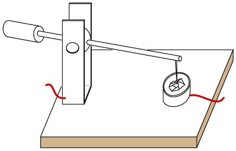
Before the modern semiconductor era, an early diode application was as a radio frequency detector, which recovered audio from a radio signal. The “semiconductor” was a polycrystalline piece of the mineral galena, lead sulfide, PbS. A pointed metallic wire known as a cat whisker was brought in contact with a spot on a crystal within the polycrystalline mineral. (Figure below) The operator labored to find a “sensitive” spot on the galena by moving the cat whisker about. Presumably, there were P and N-type spots randomly distributed throughout the crystal due to the variability of uncontrolled impurities. Less often the mineral iron pyrites, fools gold, was used, as was the mineral carborundum, silicon carbide, SiC, another detector, part of a Presumably there were P and N-type spots randomly distributed throughout the crystal due to the variability of uncontrolled impurities. Less often the mineral iron pyrites, fools gold, was used, as was the mineral carborundum, silicon carbide, SiC, another detector, part of a foxhole radio, consisted of a sharpened pencil lead bound to a bent safety pin, touching a rusty blue-blade disposable razor blade. These all required searching for a sensitive spot, easily lost because of vibration.

Crystal detector
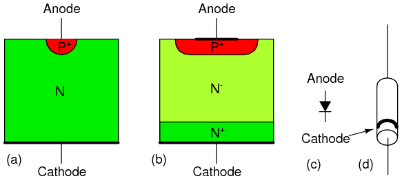
Replacing the mineral with an N-doped semiconductor (Figure below(a) ) makes the whole surface sensitive, so that searching for a sensitive spot was no longer required. This device was perfected by G.W.Pickard in 1906. The pointed metal contact produced a localized P-type region within the semiconductor. The metal point was fixed in place, and the whole point contact diode encapsulated in a cylindrical body for mechanical and electrical stability. (Figure below(d) ) Note that the cathode bar on the schematic corresponds to the bar on the physical package.
Silicon point contact diodes made an important contribution to radar in World War II, detecting giga-hertz radio frequency echo signals in the radar receiver. The concept to be made clear is that the point contact diode preceded the junction diode and modern semiconductors by several decades. Even to this day, the point contact diode is a practical means of microwave frequency detection because of its low capacitance. Germanium point contact diodes were once more readily available than they are today, being preferred for the lower 0.2 V forward voltage in some applications like self-powered crystal radios. Point contact diodes, though sensitive to a wide bandwidth, have a low current capability compared with junction diodes.

Silicon diode cross-section: (a) point contact diode, (b) junction diode, (c) schematic symbol, (d) small signal diode package.
Most diodes today are silicon junction diodes. The cross-section in Figure above(b) looks a bit more complex than a simple PN junction; though, it is still a PN junction. Starting at the cathode connection, the N+ indicates this region is heavily doped, having nothing to do with polarity. This reduces the series resistance of the diode. The N- region is lightly doped as indicated by the (-). Light doping produces a diode with a higher reverse breakdown voltage, important for high voltage power rectifier diodes. Lower voltage diodes, even low voltage power rectifiers, would have lower forward losses with heavier doping. The heaviest level of doping produces zener diodes designed for a low reverse breakdown voltage. However, heavy doping increases the reverse leakage current. The P+ region at the anode contact is heavily doped P-type semiconductor, a good contact strategy. Glass encapsulated small signal junction diodes are capable of 10’s to 100’s of mA of current. Plastic or ceramic encapsulated power rectifier diodes handle to 1000’s of amperes of current.
Review
- Point contact diodes have superb high-frequency characteristics, usable well into the microwave frequencies.
- Junction diodes range in size from small signal diodes to power rectifiers capable of 1000’s of amperes.
- The level of doping near the junction determines the reverse breakdown voltage. Light doping produces a high voltage diode. Heavy doping produces a lower breakdown voltage, and increases reverse leakage current. Zener diodes have a lower breakdown voltage because of heavy doping.


