8.14: Operational Amplifier Models
- Page ID
- 1864
\( \newcommand{\vecs}[1]{\overset { \scriptstyle \rightharpoonup} {\mathbf{#1}} } \)
\( \newcommand{\vecd}[1]{\overset{-\!-\!\rightharpoonup}{\vphantom{a}\smash {#1}}} \)
\( \newcommand{\dsum}{\displaystyle\sum\limits} \)
\( \newcommand{\dint}{\displaystyle\int\limits} \)
\( \newcommand{\dlim}{\displaystyle\lim\limits} \)
\( \newcommand{\id}{\mathrm{id}}\) \( \newcommand{\Span}{\mathrm{span}}\)
( \newcommand{\kernel}{\mathrm{null}\,}\) \( \newcommand{\range}{\mathrm{range}\,}\)
\( \newcommand{\RealPart}{\mathrm{Re}}\) \( \newcommand{\ImaginaryPart}{\mathrm{Im}}\)
\( \newcommand{\Argument}{\mathrm{Arg}}\) \( \newcommand{\norm}[1]{\| #1 \|}\)
\( \newcommand{\inner}[2]{\langle #1, #2 \rangle}\)
\( \newcommand{\Span}{\mathrm{span}}\)
\( \newcommand{\id}{\mathrm{id}}\)
\( \newcommand{\Span}{\mathrm{span}}\)
\( \newcommand{\kernel}{\mathrm{null}\,}\)
\( \newcommand{\range}{\mathrm{range}\,}\)
\( \newcommand{\RealPart}{\mathrm{Re}}\)
\( \newcommand{\ImaginaryPart}{\mathrm{Im}}\)
\( \newcommand{\Argument}{\mathrm{Arg}}\)
\( \newcommand{\norm}[1]{\| #1 \|}\)
\( \newcommand{\inner}[2]{\langle #1, #2 \rangle}\)
\( \newcommand{\Span}{\mathrm{span}}\) \( \newcommand{\AA}{\unicode[.8,0]{x212B}}\)
\( \newcommand{\vectorA}[1]{\vec{#1}} % arrow\)
\( \newcommand{\vectorAt}[1]{\vec{\text{#1}}} % arrow\)
\( \newcommand{\vectorB}[1]{\overset { \scriptstyle \rightharpoonup} {\mathbf{#1}} } \)
\( \newcommand{\vectorC}[1]{\textbf{#1}} \)
\( \newcommand{\vectorD}[1]{\overrightarrow{#1}} \)
\( \newcommand{\vectorDt}[1]{\overrightarrow{\text{#1}}} \)
\( \newcommand{\vectE}[1]{\overset{-\!-\!\rightharpoonup}{\vphantom{a}\smash{\mathbf {#1}}}} \)
\( \newcommand{\vecs}[1]{\overset { \scriptstyle \rightharpoonup} {\mathbf{#1}} } \)
\( \newcommand{\vecd}[1]{\overset{-\!-\!\rightharpoonup}{\vphantom{a}\smash {#1}}} \)
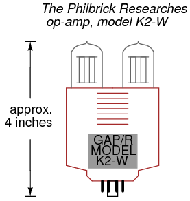
\(\newcommand{\avec}{\mathbf a}\) \(\newcommand{\bvec}{\mathbf b}\) \(\newcommand{\cvec}{\mathbf c}\) \(\newcommand{\dvec}{\mathbf d}\) \(\newcommand{\dtil}{\widetilde{\mathbf d}}\) \(\newcommand{\evec}{\mathbf e}\) \(\newcommand{\fvec}{\mathbf f}\) \(\newcommand{\nvec}{\mathbf n}\) \(\newcommand{\pvec}{\mathbf p}\) \(\newcommand{\qvec}{\mathbf q}\) \(\newcommand{\svec}{\mathbf s}\) \(\newcommand{\tvec}{\mathbf t}\) \(\newcommand{\uvec}{\mathbf u}\) \(\newcommand{\vvec}{\mathbf v}\) \(\newcommand{\wvec}{\mathbf w}\) \(\newcommand{\xvec}{\mathbf x}\) \(\newcommand{\yvec}{\mathbf y}\) \(\newcommand{\zvec}{\mathbf z}\) \(\newcommand{\rvec}{\mathbf r}\) \(\newcommand{\mvec}{\mathbf m}\) \(\newcommand{\zerovec}{\mathbf 0}\) \(\newcommand{\onevec}{\mathbf 1}\) \(\newcommand{\real}{\mathbb R}\) \(\newcommand{\twovec}[2]{\left[\begin{array}{r}#1 \\ #2 \end{array}\right]}\) \(\newcommand{\ctwovec}[2]{\left[\begin{array}{c}#1 \\ #2 \end{array}\right]}\) \(\newcommand{\threevec}[3]{\left[\begin{array}{r}#1 \\ #2 \\ #3 \end{array}\right]}\) \(\newcommand{\cthreevec}[3]{\left[\begin{array}{c}#1 \\ #2 \\ #3 \end{array}\right]}\) \(\newcommand{\fourvec}[4]{\left[\begin{array}{r}#1 \\ #2 \\ #3 \\ #4 \end{array}\right]}\) \(\newcommand{\cfourvec}[4]{\left[\begin{array}{c}#1 \\ #2 \\ #3 \\ #4 \end{array}\right]}\) \(\newcommand{\fivevec}[5]{\left[\begin{array}{r}#1 \\ #2 \\ #3 \\ #4 \\ #5 \\ \end{array}\right]}\) \(\newcommand{\cfivevec}[5]{\left[\begin{array}{c}#1 \\ #2 \\ #3 \\ #4 \\ #5 \\ \end{array}\right]}\) \(\newcommand{\mattwo}[4]{\left[\begin{array}{rr}#1 \amp #2 \\ #3 \amp #4 \\ \end{array}\right]}\) \(\newcommand{\laspan}[1]{\text{Span}\{#1\}}\) \(\newcommand{\bcal}{\cal B}\) \(\newcommand{\ccal}{\cal C}\) \(\newcommand{\scal}{\cal S}\) \(\newcommand{\wcal}{\cal W}\) \(\newcommand{\ecal}{\cal E}\) \(\newcommand{\coords}[2]{\left\{#1\right\}_{#2}}\) \(\newcommand{\gray}[1]{\color{gray}{#1}}\) \(\newcommand{\lgray}[1]{\color{lightgray}{#1}}\) \(\newcommand{\rank}{\operatorname{rank}}\) \(\newcommand{\row}{\text{Row}}\) \(\newcommand{\col}{\text{Col}}\) \(\renewcommand{\row}{\text{Row}}\) \(\newcommand{\nul}{\text{Nul}}\) \(\newcommand{\var}{\text{Var}}\) \(\newcommand{\corr}{\text{corr}}\) \(\newcommand{\len}[1]{\left|#1\right|}\) \(\newcommand{\bbar}{\overline{\bvec}}\) \(\newcommand{\bhat}{\widehat{\bvec}}\) \(\newcommand{\bperp}{\bvec^\perp}\) \(\newcommand{\xhat}{\widehat{\xvec}}\) \(\newcommand{\vhat}{\widehat{\vvec}}\) \(\newcommand{\uhat}{\widehat{\uvec}}\) \(\newcommand{\what}{\widehat{\wvec}}\) \(\newcommand{\Sighat}{\widehat{\Sigma}}\) \(\newcommand{\lt}{<}\) \(\newcommand{\gt}{>}\) \(\newcommand{\amp}{&}\) \(\definecolor{fillinmathshade}{gray}{0.9}\)While mention of operational amplifiers typically provokes visions of semiconductor devices built as integrated circuits on a miniature silicon chip, the first op-amps were actually vacuum tube circuits. The first commercial, general purpose operational amplifier was manufactured by the George A. Philbrick Researches, Incorporated, in 1952. Designated the K2-W, it was built around two twin-triode tubes mounted in an assembly with an octal (8-pin) socket for easy installation and servicing in electronic equipment chassis of that era. The assembly looked something like this:

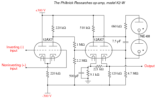
The schematic diagram shows the two tubes, along with ten resistors and two capacitors, a fairly simple circuit design even by 1952 standards:

In case you’re unfamiliar with the operation of vacuum tubes, they operate similarly to N-channel depletion-type IGFET transistors: that is, they conduct more current when the control grid (the dashed line) is made more positive with respect to the cathode (the bent line near the bottom of the tube symbol), and conduct less current when the control grid is made less positive (or more negative) than the cathode. The twin triode tube on the left functions as a differential pair, converting the differential inputs (inverting and noninverting input voltage signals) into a single, amplified voltage signal which is then fed to the control grid of the left triode of the second triode pair through a voltage divider (1 MΩ—2.2 MΩ). That triode amplifies and inverts the output of the differential pair for a larger voltage gain, then the amplified signal is coupled to the second triode of the same dual-triode tube in a noninverting amplifier configuration for a larger current gain. The two neon “glow tubes” act as voltage regulators, similar to the behavior of semiconductor zener diodes, to provide a bias voltage in the coupling between the two single-ended amplifier triodes.
With a dual-supply voltage of +300/-300 volts, this op-amp could only swing its output +/- 50 volts, which is very poor by today’s standards. It had an open-loop voltage gain of 15,000 to 20,000, a slew rate of +/- 12 volts/µsecond, a maximum output current of 1 mA, a quiescent power consumption of over 3 watts (not including power for the tubes’ filaments!), and cost about $24 in 1952 dollars. Better performance could have been attained using a more sophisticated circuit design, but only at the expense of greater power consumption, greater cost, and decreased reliability.
With the advent of solid-state transistors, op-amps with far less quiescent power consumption and increased reliability became feasible, but many of the other performance parameters remained about the same. Take for instance Philbrick’s model P55A, a general-purpose solid-state op-amp circa 1966. The P55A sported an open-loop gain of 40,000, a slew rate of 1.5 volt/µsecond and an output swing of +/- 11 volts (at a power supply voltage of +/- 15 volts), a maximum output current of 2.2 mA, and a cost of $49 (or about $21 for the “utility grade” version). The P55A, as well as other op-amps in Philbrick’s lineup of the time, was of discrete-component construction, its constituent transistors, resistors, and capacitors housed in a solid “brick” resembling a large integrated circuit package.
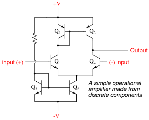
It isn’t very difficult to build a crude operational amplifier using discrete components. A schematic of one such circuit is shown in Figure below.

A simple operational amplifier made from discrete components.
While its performance is rather dismal by modern standards, it demonstrates that complexity is not necessary to create a minimally functional op-amp. Transistors Q3 and Q4 form the heart of another differential pair circuit, the semiconductor equivalent of the first triode tube in the K2-W schematic. As it was in the vacuum tube circuit, the purpose of a differential pair is to amplify and convert a differential voltage between the two input terminals to a single-ended output voltage.
With the advent of integrated-circuit (IC) technology, op-amp designs experienced a dramatic increase in performance, reliability, density, and economy. Between the years of 1964 and 1968, the Fairchild corporation introduced three models of IC op-amps: the 702, 709, and the still-popular 741. While the 741 is now considered outdated in terms of performance, it is still a favorite among hobbyists for its simplicity and fault tolerance (short-circuit protection on the output, for instance). Personal experience abusing many 741 op-amps has led me to the conclusion that it is a hard chip to kill . . .
The internal schematic diagram for a model 741 op-amp is shown in Figure below.

Schematic diagram of a model 741 op-amp.
By integrated circuit standards, the 741 is a very simple device: an example of small-scale integration, or SSI technology. It would be no small matter to build this circuit using discrete components, so you can see the advantages of even the most primitive integrated circuit technology over discrete components where high parts counts are involved.
For the hobbyist, student, or engineer desiring greater performance, there are literally hundreds of op-amp models to choose from. Many sell for less than a dollar apiece, even retail! Special-purpose instrumentation and radio-frequency (RF) op-amps may be quite a bit more expensive. In this section I will showcase several popular and affordable op-amps, comparing and contrasting their performance specifications. The venerable 741 is included as a “benchmark” for comparison, although it is, as I said before, considered an obsolete design.
Listed in Table above are but a few of the low-cost operational amplifier models widely available from electronics suppliers. Most of them are available through retail supply stores such as Radio Shack. All are under $1.00 cost direct from the manufacturer (year 2001 prices). As you can see, there is substantial variation in performance between some of these units. Take for instance the parameter of input bias current: the CA3130 wins the prize for lowest, at 0.05 nA (or 50 pA), and the LM833 has the highest at slightly over 1 µA. The model CA3130 achieves its incredibly low bias current through the use of MOSFET transistors in its input stage. One manufacturer advertises the 3130’s input impedance as 1.5 tera-ohms, or 1.5 x 10¹² Ω! Other op-amps shown here with low bias current figures use JFET input transistors, while the high bias current models use bipolar input transistors.
While the 741 is specified in many electronic project schematics and showcased in many textbooks, its performance has long been surpassed by other designs in every measure. Even some designs originally based on the 741 have been improved over the years to far surpass original design specifications. One such example is the model 1458, two op-amps in an 8-pin DIP package, which at one time had the exact same performance specifications as the single 741. In its latest incarnation it boasts a wider power supply voltage range, a slew rate 50 times as great, and almost twice the output current capability of a 741, while still retaining the output short-circuit protection feature of the 741. Op-amps with JFET and MOSFET input transistors far exceed the 741’s performance in terms of bias current, and generally manage to beat the 741 in terms of bandwidth and slew rate as well.
My own personal recommendations for op-amps are as such: when low bias current is a priority (such as in low-speed integrator circuits), choose the 3130. For general-purpose DC amplifier work, the 1458 offers good performance (and you get two op-amps in the space of one package). For an upgrade in performance, choose the model 353, as it is a pin-compatible replacement for the 1458. The 353 is designed with JFET input circuitry for very low bias current, and has a bandwidth 4 times are great as the 1458, although its output current limit is lower (but still short-circuit protected). It may be more difficult to find on the shelf of your local electronics supply house, but it is just as reasonably priced as the 1458.
If low power supply voltage is a requirement, I recommend the model 324, as it functions on as low as 3 volts DC. Its input bias current requirements are also low, and it provides four op-amps in a single 14-pin chip. Its major weakness is speed, limited to 1 MHz bandwidth and an output slew rate of only 0.25 volts per µs. For high-frequency AC amplifier circuits, the 318 is a very good “general purpose” model.
Special-purpose op-amps are available for modest cost which provide better performance specifications. Many of these are tailored for a specific type of performance advantage, such as maximum bandwidth or minimum bias current. Take for instance the op-amps, both designed for high bandwidth in Table below.
The CLC404 lists at $21.80 (almost as much as George Philbrick’s first commercial op-amp, albeit without correction for inflation), while the CLC425 is quite a bit less expensive at $3.23 per unit. In both cases high speed is achieved at the expense of high bias currents and restrictive power supply voltage ranges. Some op-amps, designed for high power output are listed in Table below.
Yes, the LM12CL actually has an output current rating of 13 amps (13,000 milliamps)! It lists at $14.40, which is not a lot of money, considering the raw power of the device. The LM7171, on the other hand, trades high current output ability for fast voltage output ability (a high slew rate). It lists at $1.19, about as low as some “general purpose” op-amps.
Amplifier packages may also be purchased as complete application circuits as opposed to bare operational amplifiers. The Burr-Brown and Analog Devices corporations, for example, both long known for their precision amplifier product lines, offer instrumentation amplifiers in pre-designed packages as well as other specialized amplifier devices. In designs where high precision and repeatability after repair is important, it might be advantageous for the circuit designer to choose such a pre-engineered amplifier “block” rather than build the circuit from individual op-amps. Of course, these units typically cost quite a bit more than individual op-amps.


