13.7: Combination Tubes
- Page ID
- 1882
\( \newcommand{\vecs}[1]{\overset { \scriptstyle \rightharpoonup} {\mathbf{#1}} } \)
\( \newcommand{\vecd}[1]{\overset{-\!-\!\rightharpoonup}{\vphantom{a}\smash {#1}}} \)
\( \newcommand{\id}{\mathrm{id}}\) \( \newcommand{\Span}{\mathrm{span}}\)
( \newcommand{\kernel}{\mathrm{null}\,}\) \( \newcommand{\range}{\mathrm{range}\,}\)
\( \newcommand{\RealPart}{\mathrm{Re}}\) \( \newcommand{\ImaginaryPart}{\mathrm{Im}}\)
\( \newcommand{\Argument}{\mathrm{Arg}}\) \( \newcommand{\norm}[1]{\| #1 \|}\)
\( \newcommand{\inner}[2]{\langle #1, #2 \rangle}\)
\( \newcommand{\Span}{\mathrm{span}}\)
\( \newcommand{\id}{\mathrm{id}}\)
\( \newcommand{\Span}{\mathrm{span}}\)
\( \newcommand{\kernel}{\mathrm{null}\,}\)
\( \newcommand{\range}{\mathrm{range}\,}\)
\( \newcommand{\RealPart}{\mathrm{Re}}\)
\( \newcommand{\ImaginaryPart}{\mathrm{Im}}\)
\( \newcommand{\Argument}{\mathrm{Arg}}\)
\( \newcommand{\norm}[1]{\| #1 \|}\)
\( \newcommand{\inner}[2]{\langle #1, #2 \rangle}\)
\( \newcommand{\Span}{\mathrm{span}}\) \( \newcommand{\AA}{\unicode[.8,0]{x212B}}\)
\( \newcommand{\vectorA}[1]{\vec{#1}} % arrow\)
\( \newcommand{\vectorAt}[1]{\vec{\text{#1}}} % arrow\)
\( \newcommand{\vectorB}[1]{\overset { \scriptstyle \rightharpoonup} {\mathbf{#1}} } \)
\( \newcommand{\vectorC}[1]{\textbf{#1}} \)
\( \newcommand{\vectorD}[1]{\overrightarrow{#1}} \)
\( \newcommand{\vectorDt}[1]{\overrightarrow{\text{#1}}} \)
\( \newcommand{\vectE}[1]{\overset{-\!-\!\rightharpoonup}{\vphantom{a}\smash{\mathbf {#1}}}} \)
\( \newcommand{\vecs}[1]{\overset { \scriptstyle \rightharpoonup} {\mathbf{#1}} } \)
\( \newcommand{\vecd}[1]{\overset{-\!-\!\rightharpoonup}{\vphantom{a}\smash {#1}}} \)
\(\newcommand{\avec}{\mathbf a}\) \(\newcommand{\bvec}{\mathbf b}\) \(\newcommand{\cvec}{\mathbf c}\) \(\newcommand{\dvec}{\mathbf d}\) \(\newcommand{\dtil}{\widetilde{\mathbf d}}\) \(\newcommand{\evec}{\mathbf e}\) \(\newcommand{\fvec}{\mathbf f}\) \(\newcommand{\nvec}{\mathbf n}\) \(\newcommand{\pvec}{\mathbf p}\) \(\newcommand{\qvec}{\mathbf q}\) \(\newcommand{\svec}{\mathbf s}\) \(\newcommand{\tvec}{\mathbf t}\) \(\newcommand{\uvec}{\mathbf u}\) \(\newcommand{\vvec}{\mathbf v}\) \(\newcommand{\wvec}{\mathbf w}\) \(\newcommand{\xvec}{\mathbf x}\) \(\newcommand{\yvec}{\mathbf y}\) \(\newcommand{\zvec}{\mathbf z}\) \(\newcommand{\rvec}{\mathbf r}\) \(\newcommand{\mvec}{\mathbf m}\) \(\newcommand{\zerovec}{\mathbf 0}\) \(\newcommand{\onevec}{\mathbf 1}\) \(\newcommand{\real}{\mathbb R}\) \(\newcommand{\twovec}[2]{\left[\begin{array}{r}#1 \\ #2 \end{array}\right]}\) \(\newcommand{\ctwovec}[2]{\left[\begin{array}{c}#1 \\ #2 \end{array}\right]}\) \(\newcommand{\threevec}[3]{\left[\begin{array}{r}#1 \\ #2 \\ #3 \end{array}\right]}\) \(\newcommand{\cthreevec}[3]{\left[\begin{array}{c}#1 \\ #2 \\ #3 \end{array}\right]}\) \(\newcommand{\fourvec}[4]{\left[\begin{array}{r}#1 \\ #2 \\ #3 \\ #4 \end{array}\right]}\) \(\newcommand{\cfourvec}[4]{\left[\begin{array}{c}#1 \\ #2 \\ #3 \\ #4 \end{array}\right]}\) \(\newcommand{\fivevec}[5]{\left[\begin{array}{r}#1 \\ #2 \\ #3 \\ #4 \\ #5 \\ \end{array}\right]}\) \(\newcommand{\cfivevec}[5]{\left[\begin{array}{c}#1 \\ #2 \\ #3 \\ #4 \\ #5 \\ \end{array}\right]}\) \(\newcommand{\mattwo}[4]{\left[\begin{array}{rr}#1 \amp #2 \\ #3 \amp #4 \\ \end{array}\right]}\) \(\newcommand{\laspan}[1]{\text{Span}\{#1\}}\) \(\newcommand{\bcal}{\cal B}\) \(\newcommand{\ccal}{\cal C}\) \(\newcommand{\scal}{\cal S}\) \(\newcommand{\wcal}{\cal W}\) \(\newcommand{\ecal}{\cal E}\) \(\newcommand{\coords}[2]{\left\{#1\right\}_{#2}}\) \(\newcommand{\gray}[1]{\color{gray}{#1}}\) \(\newcommand{\lgray}[1]{\color{lightgray}{#1}}\) \(\newcommand{\rank}{\operatorname{rank}}\) \(\newcommand{\row}{\text{Row}}\) \(\newcommand{\col}{\text{Col}}\) \(\renewcommand{\row}{\text{Row}}\) \(\newcommand{\nul}{\text{Nul}}\) \(\newcommand{\var}{\text{Var}}\) \(\newcommand{\corr}{\text{corr}}\) \(\newcommand{\len}[1]{\left|#1\right|}\) \(\newcommand{\bbar}{\overline{\bvec}}\) \(\newcommand{\bhat}{\widehat{\bvec}}\) \(\newcommand{\bperp}{\bvec^\perp}\) \(\newcommand{\xhat}{\widehat{\xvec}}\) \(\newcommand{\vhat}{\widehat{\vvec}}\) \(\newcommand{\uhat}{\widehat{\uvec}}\) \(\newcommand{\what}{\widehat{\wvec}}\) \(\newcommand{\Sighat}{\widehat{\Sigma}}\) \(\newcommand{\lt}{<}\) \(\newcommand{\gt}{>}\) \(\newcommand{\amp}{&}\) \(\definecolor{fillinmathshade}{gray}{0.9}\)Similar in thought to the idea of the integrated circuit, tube designers tried integrating different tube functions into single tube envelopes to reduce space requirements in more modern tube-type electronic equipment. A common combination seen within a single glass shell was two either diodes or two triodes. The idea of fitting pairs of diodes inside a single envelope makes a lot of sense in light of power supply full-wave rectifier designs, always requiring multiple diodes.
Of course, it would have been quite impossible to combine thousands of tube elements into a single tube envelope the way that thousands of transistors can be etched onto a single piece of silicon, but engineers still did their best to push the limits of tube miniaturization and consolidation. Some of these tubes, whimsically called compactrons, held four or more complete tube elements within a single envelope.
Sometimes the functions of two different tubes could be integrated into a single, combination tube in a way that simply worked more elegantly than two tubes ever could. An example of this was the pentagrid converter, more generally called a heptode, used in some superheterodyne radio designs. These tubes contained seven elements: 5 grids plus a cathode and a plate. Two of the grids were normally reserved for signal input, the other three relegated to screening and suppression (performance-enhancing) functions. Combining the superheterodyne functions of oscillator and signal mixer together in one tube, the signal coupling between these two stages was intrinsic. Rather than having separate oscillator and mixer circuits, the oscillator creating an AC voltage and the mixer “mixing” that voltage with another signal, the pentagrid converter’s oscillator section created an electron stream that oscillated in intensity which then directly passed through another grid for “mixing” with another signal.
This same tube was sometimes used in a different way: by applying a DC voltage to one of the control grids, the gain of the tube could be changed for a signal impressed on the other control grid. This was known as variable-mu operation because the “mu” (µ) of the tube (its amplification factor, measured as a ratio of plate-to-cathode voltage change over grid-to-cathode voltage change with a constant plate current) could be altered at will by a DC control voltage signal.
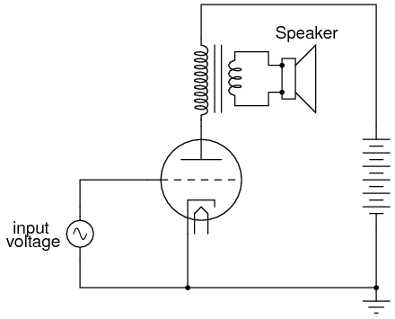
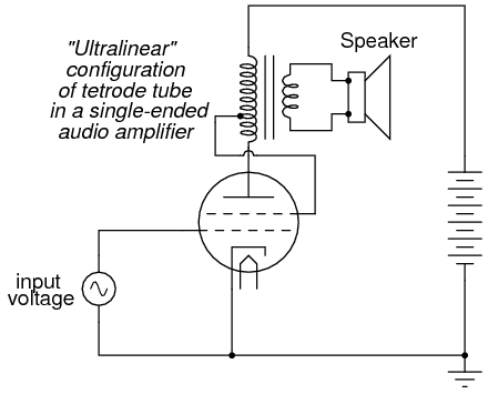
Enterprising electronics engineers also discovered ways to exploit such multi-variable capabilities of “lesser” tubes such as tetrodes and pentodes. One such way was the so-called ultralinear audio power amplifier, invented by a pair of engineers named Hafler and Keroes, utilizing a tetrode tube in combination with a “tapped” output transformer to provide substantial improvements in amplifier linearity (decreases in distortion levels). Consider a “single-ended” triode tube amplifier with an output transformer coupling power to the speaker:

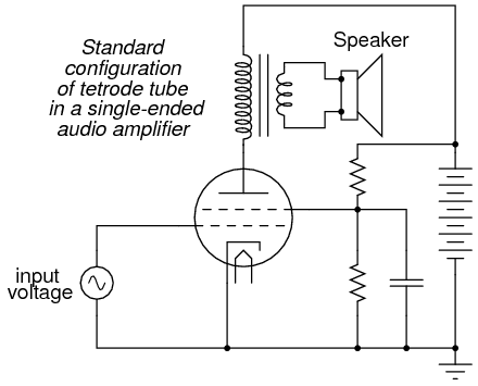
If we substitute a tetrode for a triode in this circuit, we will see improvements in circuit gain resulting from the electrostatic shielding offered by the screen, preventing unwanted feedback between the plate and control grid:

However, the tetrode’s screen may be used for functions other than merely shielding the grid from the plate. It can also be used as another control element, like the grid itself. If a “tap” is made on the transformer’s primary winding, and this tap connected to the screen, the screen will receive a voltage that varies with the signal being amplified (feedback). More specifically, the feedback signal is proportional to the rate-of-change of magnetic flux in the transformer core (dΦ/dt), thus improving the amplifier’s ability to reproduce the input signal waveform at the speaker terminals and not just in the primary winding of the transformer:

This signal feedback results in significant improvements in amplifier linearity (and consequently, distortion), so long as precautions are taken against “overpowering” the screen with too great a positive voltage with respect to the cathode. As a concept, the ultralinear (screen-feedback) design demonstrates the flexibility of operation granted by multiple grid-elements inside a single tube: a capability rarely matched by semiconductor components.
Some tube designs combined multiple tube functions in a most economic way: dual plates with a single cathode, the currents for each of the plates controlled by separate sets of control grids. Common examples of these tubes were triode-heptode and triode-hexode tubes (a hexode tube is a tube with four grids, one cathode, and one plate).
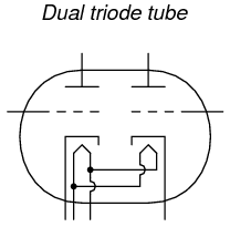
Other tube designs simply incorporated separate tube structures inside a single glass envelope for greater economy. Dual diode (rectifier) tubes were quite common, as were dual triode tubes, especially when the power dissipation of each tube was relatively low.

The 12AX7 and 12AU7 models are common examples of dual-triode tubes, both of low-power rating. The 12AX7 is especially common as a preamplifier tube in electric guitar amplifier circuits.


