1.4: Voltage and Current
- Page ID
- 679
\( \newcommand{\vecs}[1]{\overset { \scriptstyle \rightharpoonup} {\mathbf{#1}} } \)
\( \newcommand{\vecd}[1]{\overset{-\!-\!\rightharpoonup}{\vphantom{a}\smash {#1}}} \)
\( \newcommand{\id}{\mathrm{id}}\) \( \newcommand{\Span}{\mathrm{span}}\)
( \newcommand{\kernel}{\mathrm{null}\,}\) \( \newcommand{\range}{\mathrm{range}\,}\)
\( \newcommand{\RealPart}{\mathrm{Re}}\) \( \newcommand{\ImaginaryPart}{\mathrm{Im}}\)
\( \newcommand{\Argument}{\mathrm{Arg}}\) \( \newcommand{\norm}[1]{\| #1 \|}\)
\( \newcommand{\inner}[2]{\langle #1, #2 \rangle}\)
\( \newcommand{\Span}{\mathrm{span}}\)
\( \newcommand{\id}{\mathrm{id}}\)
\( \newcommand{\Span}{\mathrm{span}}\)
\( \newcommand{\kernel}{\mathrm{null}\,}\)
\( \newcommand{\range}{\mathrm{range}\,}\)
\( \newcommand{\RealPart}{\mathrm{Re}}\)
\( \newcommand{\ImaginaryPart}{\mathrm{Im}}\)
\( \newcommand{\Argument}{\mathrm{Arg}}\)
\( \newcommand{\norm}[1]{\| #1 \|}\)
\( \newcommand{\inner}[2]{\langle #1, #2 \rangle}\)
\( \newcommand{\Span}{\mathrm{span}}\) \( \newcommand{\AA}{\unicode[.8,0]{x212B}}\)
\( \newcommand{\vectorA}[1]{\vec{#1}} % arrow\)
\( \newcommand{\vectorAt}[1]{\vec{\text{#1}}} % arrow\)
\( \newcommand{\vectorB}[1]{\overset { \scriptstyle \rightharpoonup} {\mathbf{#1}} } \)
\( \newcommand{\vectorC}[1]{\textbf{#1}} \)
\( \newcommand{\vectorD}[1]{\overrightarrow{#1}} \)
\( \newcommand{\vectorDt}[1]{\overrightarrow{\text{#1}}} \)
\( \newcommand{\vectE}[1]{\overset{-\!-\!\rightharpoonup}{\vphantom{a}\smash{\mathbf {#1}}}} \)
\( \newcommand{\vecs}[1]{\overset { \scriptstyle \rightharpoonup} {\mathbf{#1}} } \)
\( \newcommand{\vecd}[1]{\overset{-\!-\!\rightharpoonup}{\vphantom{a}\smash {#1}}} \)
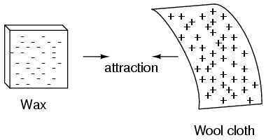
\(\newcommand{\avec}{\mathbf a}\) \(\newcommand{\bvec}{\mathbf b}\) \(\newcommand{\cvec}{\mathbf c}\) \(\newcommand{\dvec}{\mathbf d}\) \(\newcommand{\dtil}{\widetilde{\mathbf d}}\) \(\newcommand{\evec}{\mathbf e}\) \(\newcommand{\fvec}{\mathbf f}\) \(\newcommand{\nvec}{\mathbf n}\) \(\newcommand{\pvec}{\mathbf p}\) \(\newcommand{\qvec}{\mathbf q}\) \(\newcommand{\svec}{\mathbf s}\) \(\newcommand{\tvec}{\mathbf t}\) \(\newcommand{\uvec}{\mathbf u}\) \(\newcommand{\vvec}{\mathbf v}\) \(\newcommand{\wvec}{\mathbf w}\) \(\newcommand{\xvec}{\mathbf x}\) \(\newcommand{\yvec}{\mathbf y}\) \(\newcommand{\zvec}{\mathbf z}\) \(\newcommand{\rvec}{\mathbf r}\) \(\newcommand{\mvec}{\mathbf m}\) \(\newcommand{\zerovec}{\mathbf 0}\) \(\newcommand{\onevec}{\mathbf 1}\) \(\newcommand{\real}{\mathbb R}\) \(\newcommand{\twovec}[2]{\left[\begin{array}{r}#1 \\ #2 \end{array}\right]}\) \(\newcommand{\ctwovec}[2]{\left[\begin{array}{c}#1 \\ #2 \end{array}\right]}\) \(\newcommand{\threevec}[3]{\left[\begin{array}{r}#1 \\ #2 \\ #3 \end{array}\right]}\) \(\newcommand{\cthreevec}[3]{\left[\begin{array}{c}#1 \\ #2 \\ #3 \end{array}\right]}\) \(\newcommand{\fourvec}[4]{\left[\begin{array}{r}#1 \\ #2 \\ #3 \\ #4 \end{array}\right]}\) \(\newcommand{\cfourvec}[4]{\left[\begin{array}{c}#1 \\ #2 \\ #3 \\ #4 \end{array}\right]}\) \(\newcommand{\fivevec}[5]{\left[\begin{array}{r}#1 \\ #2 \\ #3 \\ #4 \\ #5 \\ \end{array}\right]}\) \(\newcommand{\cfivevec}[5]{\left[\begin{array}{c}#1 \\ #2 \\ #3 \\ #4 \\ #5 \\ \end{array}\right]}\) \(\newcommand{\mattwo}[4]{\left[\begin{array}{rr}#1 \amp #2 \\ #3 \amp #4 \\ \end{array}\right]}\) \(\newcommand{\laspan}[1]{\text{Span}\{#1\}}\) \(\newcommand{\bcal}{\cal B}\) \(\newcommand{\ccal}{\cal C}\) \(\newcommand{\scal}{\cal S}\) \(\newcommand{\wcal}{\cal W}\) \(\newcommand{\ecal}{\cal E}\) \(\newcommand{\coords}[2]{\left\{#1\right\}_{#2}}\) \(\newcommand{\gray}[1]{\color{gray}{#1}}\) \(\newcommand{\lgray}[1]{\color{lightgray}{#1}}\) \(\newcommand{\rank}{\operatorname{rank}}\) \(\newcommand{\row}{\text{Row}}\) \(\newcommand{\col}{\text{Col}}\) \(\renewcommand{\row}{\text{Row}}\) \(\newcommand{\nul}{\text{Nul}}\) \(\newcommand{\var}{\text{Var}}\) \(\newcommand{\corr}{\text{corr}}\) \(\newcommand{\len}[1]{\left|#1\right|}\) \(\newcommand{\bbar}{\overline{\bvec}}\) \(\newcommand{\bhat}{\widehat{\bvec}}\) \(\newcommand{\bperp}{\bvec^\perp}\) \(\newcommand{\xhat}{\widehat{\xvec}}\) \(\newcommand{\vhat}{\widehat{\vvec}}\) \(\newcommand{\uhat}{\widehat{\uvec}}\) \(\newcommand{\what}{\widehat{\wvec}}\) \(\newcommand{\Sighat}{\widehat{\Sigma}}\) \(\newcommand{\lt}{<}\) \(\newcommand{\gt}{>}\) \(\newcommand{\amp}{&}\) \(\definecolor{fillinmathshade}{gray}{0.9}\)If we take the examples of wax and wool which have been rubbed together, we find that the surplus of electrons in the wax (negative charge) and the deficit of electrons in the wool (positive charge) creates an imbalance of charge between them. This imbalance manifests itself as an attractive force between the two objects:
If a conductive wire is placed between the charged wax and wool, electrons will flow through it, as some of the excess electrons in the wax rush through the wire to get back to the wool, filling the deficiency of electrons there:
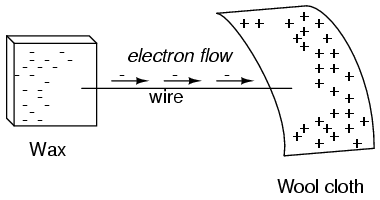
The imbalance of electrons between the atoms in the wax and the atoms in the wool creates a force between the two materials. With no path for electrons to flow from the wax to the wool, all this force can do is attract the two objects together. Now that a conductor bridges the insulating gap, however, the force will provoke electrons to flow in a uniform direction through the wire, if only momentarily, until the charge in that area neutralizes and the force between the wax and wool diminishes.
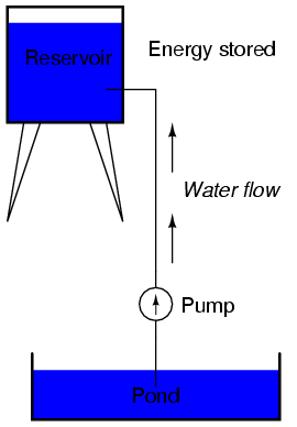
The electric charge formed between these two materials by rubbing them together serves to store a certain amount of energy. This energy is not unlike the energy stored in a high reservoir of water that has been pumped from a lower-level pond:
The influence of gravity on the water in the reservoir creates a force that attempts to move the water down to the lower level again. If a suitable pipe is run from the reservoir back to the pond, water will flow under the influence of gravity down from the reservoir, through the pipe:
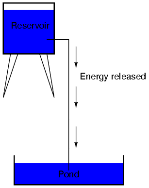
It takes energy to pump that water from the low-level pond to the high-level reservoir, and the movement of water through the piping back down to its original level constitutes a releasing of energy stored from previous pumping.
If the water is pumped to an even higher level, it will take even more energy to do so, thus more energy will be stored, and more energy released if the water is allowed to flow through a pipe back down again:
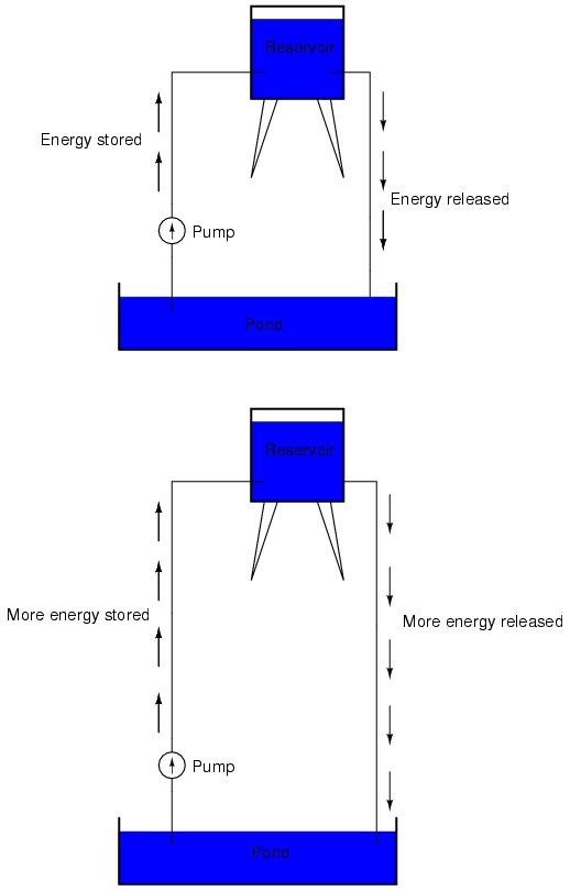
Electrons are not much different. If we rub wax and wool together, we “pump” electrons away from their normal “levels,” creating a condition where a force exists between the wax and wool, as the electrons seek to re-establish their former positions (and balance within their respective atoms). The force attracting electrons back to their original positions around the positive nuclei of their atoms is analogous to the force gravity exerts on water in the reservoir, trying to draw it down to its former level.
Just as the pumping of water to a higher level results in energy being stored, “pumping” electrons to create an electric charge imbalance results in a certain amount of energy being stored in that imbalance. And, just as providing a way for water to flow back down from the heights of the reservoir results in a release of that stored energy, providing a way for electrons to flow back to their original “levels” results in a release of stored energy.
When the electrons are poised in that static condition (just like water sitting still, high in a reservoir), the energy stored there is called potential energy, because it has the possibility (potential) of release that has not been fully realized yet. When you scuff your rubber-soled shoes against a fabric carpet on a dry day, you create an imbalance of electric charge between yourself and the carpet. The action of scuffing your feet stores energy in the form of an imbalance of electrons forced from their original locations. This charge (static electricity) is stationary, and you won’t realize that energy is being stored at all. However, once you place your hand against a metal doorknob (with lots of electron mobility to neutralize your electric charge), that stored energy will be released in the form of a sudden flow of electrons through your hand, and you will perceive it as an electric shock!
This potential energy, stored in the form of an electric charge imbalance and capable of provoking electrons to flow through a conductor, can be expressed as a term called voltage, which technically is a measure of potential energy per unit charge of electrons, or something a physicist would call specific potential energy. Defined in the context of static electricity, voltage is the measure of work required to move a unit charge from one location to another, against the force which tries to keep electric charges balanced. In the context of electrical power sources, voltage is the amount of potential energy available (work to be done) per unit charge, to move electrons through a conductor.
Because voltage is an expression of potential energy, representing the possibility or potential for energy release as the electrons move from one “level” to another, it is always referenced between two points. Consider the water reservoir analogy:
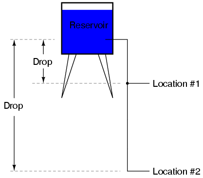
Because of the difference in the height of the drop, there’s potential for much more energy to be released from the reservoir through the piping to location 2 than to location 1. The principle can be intuitively understood in dropping a rock: which results in a more violent impact, a rock dropped from a height of one foot, or the same rock dropped from a height of one mile? Obviously, the drop of greater height results in greater energy released (a more violent impact). We cannot assess the amount of stored energy in a water reservoir simply by measuring the volume of water any more than we can predict the severity of a falling rock’s impact simply from knowing the weight of the rock: in both cases we must also consider how farthese masses will drop from their initial height. The amount of energy released by allowing a mass to drop is relative to the distance between its starting and ending points. Likewise, the potential energy available for moving electrons from one point to another is relative to those two points. Therefore, voltage is always expressed as a quantity between two points. Interestingly enough, the analogy of a mass potentially “dropping” from one height to another is such an apt model that voltage between two points is sometimes called a voltage drop.
Voltage can be generated by means other than rubbing certain types of materials against each other. Chemical reactions, radiant energy, and the influence of magnetism on conductors are a few ways in which voltage may be produced. Respective examples of these three sources of voltage are batteries, solar cells, and generators (such as the “alternator” unit under the hood of your automobile). For now, we won’t go into detail as to how each of these voltage sources works—more important is that we understand how voltage sources can be applied to create electron flow in a circuit.
Let’s take the symbol for a chemical battery and build a circuit step by step:
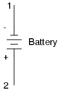
Any source of voltage, including batteries, have two points for electrical contact. In this case, we have point 1 and point 2 in the above diagram. The horizontal lines of varying length indicate that this is a battery, and they further indicate the direction which this battery’s voltage will try to push electrons through a circuit. The fact that the horizontal lines in the battery symbol appear separated (and thus unable to serve as a path for electrons to move) is no cause for concern: in real life, those horizontal lines represent metallic plates immersed in a liquid or semi-solid material that not only conducts electrons, but also generates the voltage to push them along by interacting with the plates.
Notice the little “+” and “-” signs to the immediate left of the battery symbol. The negative (-) end of the battery is always the end with the shortest dash, and the positive (+) end of the battery is always the end with the longest dash. Since we have decided to call electrons “negatively” charged (thanks, Ben!), the negative end of a battery is that end which tries to push electrons out of it. Likewise, the positive end is that end which tries to attract electrons.
With the “+” and “-” ends of the battery not connected to anything, there will be voltage between those two points, but there will be no flow of electrons through the battery, because there is no continuous path for the electrons to move.
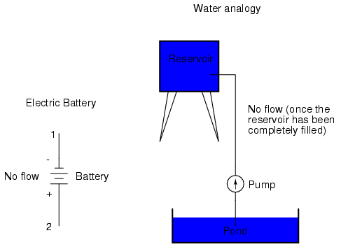
The same principle holds true for the water reservoir and pump analogy: without a return pipe back to the pond, stored energy in the reservoir cannot be released in the form of water flow. Once the reservoir is completely filled up, no flow can occur, no matter how much pressure the pump may generate. There needs to be a complete path (circuit) for water to flow from the pond, to the reservoir, and back to the pond in order for continuous flow to occur.
We can provide such a path for the battery by connecting a piece of wire from one end of the battery to the other. Forming a circuit with a loop of wire, we will initiate a continuous flow of electrons in a clockwise direction:
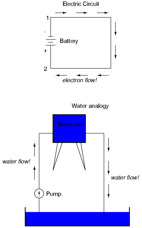
So long as the battery continues to produce voltage and the continuity of the electrical path isn’t broken, electrons will continue to flow in the circuit. Following the metaphor of water moving through a pipe, this continuous, uniform flow of electrons through the circuit is called a current. So long as the voltage source keeps “pushing” in the same direction, the electron flow will continue to move in the same direction in the circuit. This single-direction flow of electrons is called a Direct Current, or DC. In the second volume of this book series, electric circuits are explored where the direction of current switches back and forth: Alternating Current, or AC. But for now, we’ll just concern ourselves with DC circuits.
Because electric current is composed of individual electrons flowing in unison through a conductor by moving along and pushing on the electrons ahead, just like marbles through a tube or water through a pipe, the amount of flow throughout a single circuit will be the same at any point. If we were to monitor a cross-section of the wire in a single circuit, counting the electrons flowing by, we would notice the exact same quantity per unit of time as in any other part of the circuit, regardless of conductor length or conductor diameter.
If we break the circuit’s continuity at any point, the electric current will cease in the entire loop, and the full voltage produced by the battery will be manifested across the break, between the wire ends that used to be connected:
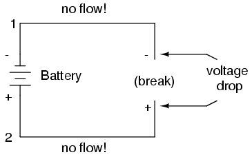
Notice the “+” and “-” signs drawn at the ends of the break in the circuit, and how they correspond to the “+” and “-” signs next to the battery’s terminals. These markers indicate the direction that the voltage attempts to push electron flow, that potential direction commonly referred to as polarity. Remember that voltage is always relative between two points. Because of this fact, the polarity of a voltage drop is also relative between two points: whether a point in a circuit gets labeled with a “+” or a “-” depends on the other point to which it is referenced. Take a look at the following circuit, where each corner of the loop is marked with a number for reference:
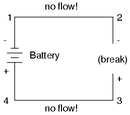
With the circuit’s continuity broken between points 2 and 3, the polarity of the voltage dropped between points 2 and 3 is “-” for point 2 and “+” for point 3. The battery’s polarity (1 “-” and 4 “+”) is trying to push electrons through the loop clockwise from 1 to 2 to 3 to 4 and back to 1 again.
Now let’s see what happens if we connect points 2 and 3 back together again, but place a break in the circuit between points 3 and 4:
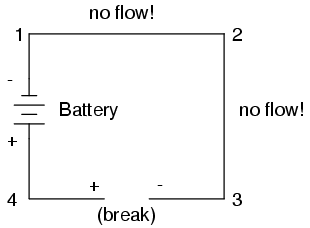
With the break between 3 and 4, the polarity of the voltage drop between those two points is “+” for 4 and “-” for 3. Take special note of the fact that point 3’s “sign” is opposite of that in the first example, where the break was between points 2 and 3 (where point 3 was labeled “+”). It is impossible for us to say that point 3 in this circuit will always be either “+” or “-”, because polarity, like voltage itself, is not specific to a single point, but is always relative between two points!
Review
- Electrons can be motivated to flow through a conductor by the same force manifested in static electricity.
- Voltage is the measure of specific potential energy (potential energy per unit charge) between two locations. In layman’s terms, it is the measure of “push” available to motivate electrons.
- Voltage, as an expression of potential energy, is always relative between two locations, or points. Sometimes it is called a voltage “drop.”
- When a voltage source is connected to a circuit, the voltage will cause a uniform flow of electrons through that circuit called a current.
- In a single (one loop) circuit, the amount of current at any point is the same as the amount of current at any other point.
- If a circuit containing a voltage source is broken, the full voltage of that source will appear across the points of the break.
- The +/- orientation of a voltage drop is called the polarity. It is also relative between two points.


