3.8: Safe Circuit Design
- Page ID
- 701
\( \newcommand{\vecs}[1]{\overset { \scriptstyle \rightharpoonup} {\mathbf{#1}} } \)
\( \newcommand{\vecd}[1]{\overset{-\!-\!\rightharpoonup}{\vphantom{a}\smash {#1}}} \)
\( \newcommand{\id}{\mathrm{id}}\) \( \newcommand{\Span}{\mathrm{span}}\)
( \newcommand{\kernel}{\mathrm{null}\,}\) \( \newcommand{\range}{\mathrm{range}\,}\)
\( \newcommand{\RealPart}{\mathrm{Re}}\) \( \newcommand{\ImaginaryPart}{\mathrm{Im}}\)
\( \newcommand{\Argument}{\mathrm{Arg}}\) \( \newcommand{\norm}[1]{\| #1 \|}\)
\( \newcommand{\inner}[2]{\langle #1, #2 \rangle}\)
\( \newcommand{\Span}{\mathrm{span}}\)
\( \newcommand{\id}{\mathrm{id}}\)
\( \newcommand{\Span}{\mathrm{span}}\)
\( \newcommand{\kernel}{\mathrm{null}\,}\)
\( \newcommand{\range}{\mathrm{range}\,}\)
\( \newcommand{\RealPart}{\mathrm{Re}}\)
\( \newcommand{\ImaginaryPart}{\mathrm{Im}}\)
\( \newcommand{\Argument}{\mathrm{Arg}}\)
\( \newcommand{\norm}[1]{\| #1 \|}\)
\( \newcommand{\inner}[2]{\langle #1, #2 \rangle}\)
\( \newcommand{\Span}{\mathrm{span}}\) \( \newcommand{\AA}{\unicode[.8,0]{x212B}}\)
\( \newcommand{\vectorA}[1]{\vec{#1}} % arrow\)
\( \newcommand{\vectorAt}[1]{\vec{\text{#1}}} % arrow\)
\( \newcommand{\vectorB}[1]{\overset { \scriptstyle \rightharpoonup} {\mathbf{#1}} } \)
\( \newcommand{\vectorC}[1]{\textbf{#1}} \)
\( \newcommand{\vectorD}[1]{\overrightarrow{#1}} \)
\( \newcommand{\vectorDt}[1]{\overrightarrow{\text{#1}}} \)
\( \newcommand{\vectE}[1]{\overset{-\!-\!\rightharpoonup}{\vphantom{a}\smash{\mathbf {#1}}}} \)
\( \newcommand{\vecs}[1]{\overset { \scriptstyle \rightharpoonup} {\mathbf{#1}} } \)
\( \newcommand{\vecd}[1]{\overset{-\!-\!\rightharpoonup}{\vphantom{a}\smash {#1}}} \)
\(\newcommand{\avec}{\mathbf a}\) \(\newcommand{\bvec}{\mathbf b}\) \(\newcommand{\cvec}{\mathbf c}\) \(\newcommand{\dvec}{\mathbf d}\) \(\newcommand{\dtil}{\widetilde{\mathbf d}}\) \(\newcommand{\evec}{\mathbf e}\) \(\newcommand{\fvec}{\mathbf f}\) \(\newcommand{\nvec}{\mathbf n}\) \(\newcommand{\pvec}{\mathbf p}\) \(\newcommand{\qvec}{\mathbf q}\) \(\newcommand{\svec}{\mathbf s}\) \(\newcommand{\tvec}{\mathbf t}\) \(\newcommand{\uvec}{\mathbf u}\) \(\newcommand{\vvec}{\mathbf v}\) \(\newcommand{\wvec}{\mathbf w}\) \(\newcommand{\xvec}{\mathbf x}\) \(\newcommand{\yvec}{\mathbf y}\) \(\newcommand{\zvec}{\mathbf z}\) \(\newcommand{\rvec}{\mathbf r}\) \(\newcommand{\mvec}{\mathbf m}\) \(\newcommand{\zerovec}{\mathbf 0}\) \(\newcommand{\onevec}{\mathbf 1}\) \(\newcommand{\real}{\mathbb R}\) \(\newcommand{\twovec}[2]{\left[\begin{array}{r}#1 \\ #2 \end{array}\right]}\) \(\newcommand{\ctwovec}[2]{\left[\begin{array}{c}#1 \\ #2 \end{array}\right]}\) \(\newcommand{\threevec}[3]{\left[\begin{array}{r}#1 \\ #2 \\ #3 \end{array}\right]}\) \(\newcommand{\cthreevec}[3]{\left[\begin{array}{c}#1 \\ #2 \\ #3 \end{array}\right]}\) \(\newcommand{\fourvec}[4]{\left[\begin{array}{r}#1 \\ #2 \\ #3 \\ #4 \end{array}\right]}\) \(\newcommand{\cfourvec}[4]{\left[\begin{array}{c}#1 \\ #2 \\ #3 \\ #4 \end{array}\right]}\) \(\newcommand{\fivevec}[5]{\left[\begin{array}{r}#1 \\ #2 \\ #3 \\ #4 \\ #5 \\ \end{array}\right]}\) \(\newcommand{\cfivevec}[5]{\left[\begin{array}{c}#1 \\ #2 \\ #3 \\ #4 \\ #5 \\ \end{array}\right]}\) \(\newcommand{\mattwo}[4]{\left[\begin{array}{rr}#1 \amp #2 \\ #3 \amp #4 \\ \end{array}\right]}\) \(\newcommand{\laspan}[1]{\text{Span}\{#1\}}\) \(\newcommand{\bcal}{\cal B}\) \(\newcommand{\ccal}{\cal C}\) \(\newcommand{\scal}{\cal S}\) \(\newcommand{\wcal}{\cal W}\) \(\newcommand{\ecal}{\cal E}\) \(\newcommand{\coords}[2]{\left\{#1\right\}_{#2}}\) \(\newcommand{\gray}[1]{\color{gray}{#1}}\) \(\newcommand{\lgray}[1]{\color{lightgray}{#1}}\) \(\newcommand{\rank}{\operatorname{rank}}\) \(\newcommand{\row}{\text{Row}}\) \(\newcommand{\col}{\text{Col}}\) \(\renewcommand{\row}{\text{Row}}\) \(\newcommand{\nul}{\text{Nul}}\) \(\newcommand{\var}{\text{Var}}\) \(\newcommand{\corr}{\text{corr}}\) \(\newcommand{\len}[1]{\left|#1\right|}\) \(\newcommand{\bbar}{\overline{\bvec}}\) \(\newcommand{\bhat}{\widehat{\bvec}}\) \(\newcommand{\bperp}{\bvec^\perp}\) \(\newcommand{\xhat}{\widehat{\xvec}}\) \(\newcommand{\vhat}{\widehat{\vvec}}\) \(\newcommand{\uhat}{\widehat{\uvec}}\) \(\newcommand{\what}{\widehat{\wvec}}\) \(\newcommand{\Sighat}{\widehat{\Sigma}}\) \(\newcommand{\lt}{<}\) \(\newcommand{\gt}{>}\) \(\newcommand{\amp}{&}\) \(\definecolor{fillinmathshade}{gray}{0.9}\)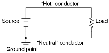
As far as the voltage source and load are concerned, grounding makes no difference at all. It exists purely for the sake of personnel safety, by guaranteeing that at least one point in the circuit will be safe to touch (zero voltage to ground). The “Hot” side of the circuit, named for its potential for shock hazard, will be dangerous to touch unless voltage is secured by proper disconnection from the source (ideally, using a systematic lock-out/tag-out procedure).
This imbalance of hazard between the two conductors in a simple power circuit is important to understand. The following series of illustrations are based on common household wiring systems (using DC voltage sources rather than AC for simplicity).
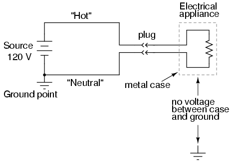
If we take a look at a simple, household electrical appliance such as a toaster with a conductive metal case, we can see that there should be no shock hazard when it is operating properly. The wires conducting power to the toaster’s heating element are insulated from touching the metal case (and each other) by rubber or plastic.
However, if one of the wires inside the toaster were to accidentally come in contact with the metal case, the case will be made electrically common to the wire, and touching the case will be just as hazardous as touching the wire bare. Whether or not this presents a shock hazard depends on which wire accidentally touches:
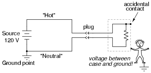
If the “hot” wire contacts the case, it places the user of the toaster in danger. On the other hand, if the neutral wire contacts the case, there is no danger of shock:
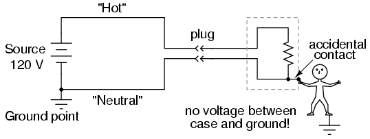
To help ensure that the former failure is less likely than the latter, engineers try to design appliances in such a way as to minimize hot conductor contact with the case. Ideally, of course, you don’t want either wire accidentally coming in contact with the conductive case of the appliance, but there are usually ways to design the layout of the parts to make accidental contact less likely for one wire than for the other. However, this preventative measure is effective only if power plug polarity can be guaranteed. If the plug can be reversed, then the conductor more likely to contact the case might very well be the “hot” one:
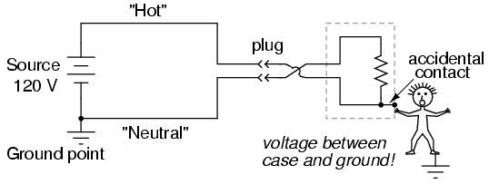
Appliances designed this way usually come with “polarized” plugs, one prong of the plug being slightly narrower than the other. Power receptacles are also designed like this, one slot being narrower than the other. Consequently, the plug cannot be inserted “backwards,” and conductor identity inside the appliance can be guaranteed. Remember that this has no effect whatsoever on the basic function of the appliance: its strictly for the sake of user safety.
Some engineers address the safety issue simply by making the outside case of the appliance nonconductive. Such appliances are called double-insulated, since the insulating case serves as a second layer of insulation above and beyond that of the conductors themselves. If a wire inside the appliance accidently comes in contact with the case, there is no danger presented to the user of the appliance.
Other engineers tackle the problem of safety by maintaining a conductive case, but using a third conductor to firmly connect that case to ground:
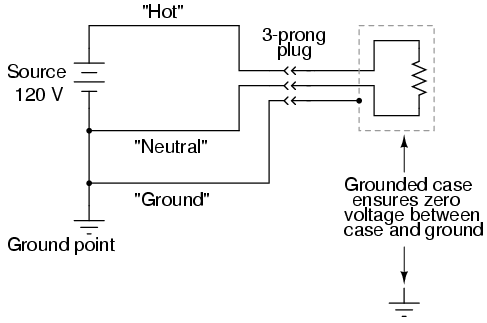
The third prong on the power cord provides a direct electrical connection from the appliance case to earth ground, making the two points electrically common with each other. If they’re electrically common, then there cannot be any voltage dropped between them. At least, that’s how it is supposed to work. If the hot conductor accidently touches the metal appliance case, it will create a direct short-circuit back to the voltage source through the ground wire, tripping any overcurrent protection devices. The user of the appliance will remain safe.
This is why its so important never to cut the third prong off a power plug when trying to fit it into a two-prong receptacle. If this is done, there will be no grounding of the appliance case to keep the user(s) safe. The appliance will still function properly, but if there is an internal fault bringing the hot wire in contact with the case, the results can be deadly. If a two-prong receptacle must be used, a two- to three-prong receptacle adapter can be installed with a grounding wire attached to the receptacle’s grounded cover screw. This will maintain the safety of the grounded appliance while plugged in to this type of receptacle.
Electrically safe engineering doesn’t necessarily end at the load, however. A final safeguard against electrical shock can be arranged on the power supply side of the circuit rather than the appliance itself. This safeguard is called ground-fault detection, and it works like this:
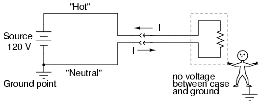
In a properly functioning appliance (shown above), the current measured through the hot conductor should be exactly equal to the current through the neutral conductor, because there’s only one path for electrons to flow in the circuit. With no fault inside the appliance, there is no connection between circuit conductors and the person touching the case, and therefore no shock.
If, however, the hot wire accidentally contacts the metal case, there will be current through the person touching the case. The presence of a shock current will be manifested as a difference of current between the two power conductors at the receptacle:
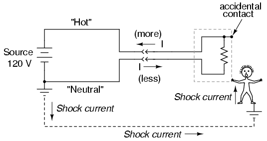
This difference in current between the “hot” and “neutral” conductors will only exist if there is current through the ground connection, meaning that there is a fault in the system. Therefore, such a current difference can be used as a way to detect a fault condition. If a device is set up to measure this difference of current between the two power conductors, a detection of current imbalance can be used to trigger the opening of a disconnect switch, thus cutting power off and preventing serious shock:
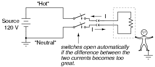
Such devices are called Ground Fault Current Interruptors, or GFCIs for short. Outside North America, the GFCI is variously known as a safety switch, a residual current device (RCD), an RCBO or RCD/MCB if combined with a miniature circuit breaker, or earth leakage circuit breaker (ELCB). They are compact enough to be built into a power receptacle. These receptacles are easily identified by their distinctive “Test” and “Reset” buttons. The big advantage with using this approach to ensure safety is that it works regardless of the appliance’s design. Of course, using a double-insulated or grounded appliance in addition to a GFCI receptacle would be better yet, but its comforting to know that something can be done to improve safety above and beyond the design and condition of the appliance.
The arc fault circuit interrupter (AFCI), a circuit breaker designed to prevent fires, is designed to open on intermittent resistive short circuits. For example, a normal 15 A breaker is designed to open circuit quickly if loaded well beyond the 15 A rating, more slowly a little beyond the rating. While this protects against direct shorts and several seconds of overload, respectively, it does not protect against arcs– similar to arc-welding. An arc is a highly variable load, repetitively peaking at over 70 A, open circuiting with alternating current zero-crossings. Though, the average current is not enough to trip a standard breaker, it is enough to start a fire. This arc could be created by a metalic short circuit which burns the metal open, leaving a resistive sputtering plasma of ionized gases.
The AFCI contains electronic circuitry to sense this intermittent resistive short circuit. It protects against both hot to neutral and hot to ground arcs. The AFCI does not protect against personal shock hazards like a GFCI does. Thus, GFCIs still need to be installed in kitchen, bath, and outdoors circuits. Since the AFCI often trips upon starting large motors, and more generally on brushed motors, its installation is limited to bedroom circuits by the U.S. National Electrical code. Use of the AFCI should reduce the number of electrical fires. However, nuisance-trips when running appliances with motors on AFCI circuits is a problem.
Review
- Power systems often have one side of the voltage supply connected to earth ground to ensure safety at that point.
- The “grounded” conductor in a power system is called the neutral conductor, while the ungrounded conductor is called the hot.
- Grounding in power systems exists for the sake of personnel safety, not the operation of the load(s).
- Electrical safety of an appliance or other load can be improved by good engineering: polarized plugs, double insulation, and three-prong “grounding” plugs are all ways that safety can be maximized on the load side.
- Ground Fault Current Interruptors (GFCIs) work by sensing a difference in current between the two conductors supplying power to the load. There should be no difference in current at all. Any difference means that current must be entering or exiting the load by some means other than the two main conductors, which is not good. A significant current difference will automatically open a disconnecting switch mechanism, cutting power off completely.


