12.2: Conductor Size
- Page ID
- 1039
\( \newcommand{\vecs}[1]{\overset { \scriptstyle \rightharpoonup} {\mathbf{#1}} } \)
\( \newcommand{\vecd}[1]{\overset{-\!-\!\rightharpoonup}{\vphantom{a}\smash {#1}}} \)
\( \newcommand{\id}{\mathrm{id}}\) \( \newcommand{\Span}{\mathrm{span}}\)
( \newcommand{\kernel}{\mathrm{null}\,}\) \( \newcommand{\range}{\mathrm{range}\,}\)
\( \newcommand{\RealPart}{\mathrm{Re}}\) \( \newcommand{\ImaginaryPart}{\mathrm{Im}}\)
\( \newcommand{\Argument}{\mathrm{Arg}}\) \( \newcommand{\norm}[1]{\| #1 \|}\)
\( \newcommand{\inner}[2]{\langle #1, #2 \rangle}\)
\( \newcommand{\Span}{\mathrm{span}}\)
\( \newcommand{\id}{\mathrm{id}}\)
\( \newcommand{\Span}{\mathrm{span}}\)
\( \newcommand{\kernel}{\mathrm{null}\,}\)
\( \newcommand{\range}{\mathrm{range}\,}\)
\( \newcommand{\RealPart}{\mathrm{Re}}\)
\( \newcommand{\ImaginaryPart}{\mathrm{Im}}\)
\( \newcommand{\Argument}{\mathrm{Arg}}\)
\( \newcommand{\norm}[1]{\| #1 \|}\)
\( \newcommand{\inner}[2]{\langle #1, #2 \rangle}\)
\( \newcommand{\Span}{\mathrm{span}}\) \( \newcommand{\AA}{\unicode[.8,0]{x212B}}\)
\( \newcommand{\vectorA}[1]{\vec{#1}} % arrow\)
\( \newcommand{\vectorAt}[1]{\vec{\text{#1}}} % arrow\)
\( \newcommand{\vectorB}[1]{\overset { \scriptstyle \rightharpoonup} {\mathbf{#1}} } \)
\( \newcommand{\vectorC}[1]{\textbf{#1}} \)
\( \newcommand{\vectorD}[1]{\overrightarrow{#1}} \)
\( \newcommand{\vectorDt}[1]{\overrightarrow{\text{#1}}} \)
\( \newcommand{\vectE}[1]{\overset{-\!-\!\rightharpoonup}{\vphantom{a}\smash{\mathbf {#1}}}} \)
\( \newcommand{\vecs}[1]{\overset { \scriptstyle \rightharpoonup} {\mathbf{#1}} } \)
\( \newcommand{\vecd}[1]{\overset{-\!-\!\rightharpoonup}{\vphantom{a}\smash {#1}}} \)
\(\newcommand{\avec}{\mathbf a}\) \(\newcommand{\bvec}{\mathbf b}\) \(\newcommand{\cvec}{\mathbf c}\) \(\newcommand{\dvec}{\mathbf d}\) \(\newcommand{\dtil}{\widetilde{\mathbf d}}\) \(\newcommand{\evec}{\mathbf e}\) \(\newcommand{\fvec}{\mathbf f}\) \(\newcommand{\nvec}{\mathbf n}\) \(\newcommand{\pvec}{\mathbf p}\) \(\newcommand{\qvec}{\mathbf q}\) \(\newcommand{\svec}{\mathbf s}\) \(\newcommand{\tvec}{\mathbf t}\) \(\newcommand{\uvec}{\mathbf u}\) \(\newcommand{\vvec}{\mathbf v}\) \(\newcommand{\wvec}{\mathbf w}\) \(\newcommand{\xvec}{\mathbf x}\) \(\newcommand{\yvec}{\mathbf y}\) \(\newcommand{\zvec}{\mathbf z}\) \(\newcommand{\rvec}{\mathbf r}\) \(\newcommand{\mvec}{\mathbf m}\) \(\newcommand{\zerovec}{\mathbf 0}\) \(\newcommand{\onevec}{\mathbf 1}\) \(\newcommand{\real}{\mathbb R}\) \(\newcommand{\twovec}[2]{\left[\begin{array}{r}#1 \\ #2 \end{array}\right]}\) \(\newcommand{\ctwovec}[2]{\left[\begin{array}{c}#1 \\ #2 \end{array}\right]}\) \(\newcommand{\threevec}[3]{\left[\begin{array}{r}#1 \\ #2 \\ #3 \end{array}\right]}\) \(\newcommand{\cthreevec}[3]{\left[\begin{array}{c}#1 \\ #2 \\ #3 \end{array}\right]}\) \(\newcommand{\fourvec}[4]{\left[\begin{array}{r}#1 \\ #2 \\ #3 \\ #4 \end{array}\right]}\) \(\newcommand{\cfourvec}[4]{\left[\begin{array}{c}#1 \\ #2 \\ #3 \\ #4 \end{array}\right]}\) \(\newcommand{\fivevec}[5]{\left[\begin{array}{r}#1 \\ #2 \\ #3 \\ #4 \\ #5 \\ \end{array}\right]}\) \(\newcommand{\cfivevec}[5]{\left[\begin{array}{c}#1 \\ #2 \\ #3 \\ #4 \\ #5 \\ \end{array}\right]}\) \(\newcommand{\mattwo}[4]{\left[\begin{array}{rr}#1 \amp #2 \\ #3 \amp #4 \\ \end{array}\right]}\) \(\newcommand{\laspan}[1]{\text{Span}\{#1\}}\) \(\newcommand{\bcal}{\cal B}\) \(\newcommand{\ccal}{\cal C}\) \(\newcommand{\scal}{\cal S}\) \(\newcommand{\wcal}{\cal W}\) \(\newcommand{\ecal}{\cal E}\) \(\newcommand{\coords}[2]{\left\{#1\right\}_{#2}}\) \(\newcommand{\gray}[1]{\color{gray}{#1}}\) \(\newcommand{\lgray}[1]{\color{lightgray}{#1}}\) \(\newcommand{\rank}{\operatorname{rank}}\) \(\newcommand{\row}{\text{Row}}\) \(\newcommand{\col}{\text{Col}}\) \(\renewcommand{\row}{\text{Row}}\) \(\newcommand{\nul}{\text{Nul}}\) \(\newcommand{\var}{\text{Var}}\) \(\newcommand{\corr}{\text{corr}}\) \(\newcommand{\len}[1]{\left|#1\right|}\) \(\newcommand{\bbar}{\overline{\bvec}}\) \(\newcommand{\bhat}{\widehat{\bvec}}\) \(\newcommand{\bperp}{\bvec^\perp}\) \(\newcommand{\xhat}{\widehat{\xvec}}\) \(\newcommand{\vhat}{\widehat{\vvec}}\) \(\newcommand{\uhat}{\widehat{\uvec}}\) \(\newcommand{\what}{\widehat{\wvec}}\) \(\newcommand{\Sighat}{\widehat{\Sigma}}\) \(\newcommand{\lt}{<}\) \(\newcommand{\gt}{>}\) \(\newcommand{\amp}{&}\) \(\definecolor{fillinmathshade}{gray}{0.9}\)Two Basic Varieties of Electrical Wire: Solid and Stranded
Electrical wire is usually round in cross-section (although there are some unique exceptions to this rule), and comes in two basic varieties: solid and stranded. Solid copper wire is just as it sounds: a single, solid strand of copper the whole length of the wire. Stranded wire is composed of smaller strands of solid copper wire twisted together to form a single, larger conductor. The greatest benefit of stranded wire is its mechanical flexibility, being able to withstand repeated bending and twisting much better than solid copper (which tends to fatigue and break after time).
Wire size can be measured in several ways. We could speak of a wire’s diameter, but since its really the cross-sectional area that matters most regarding the flow of electrons, we are better off designating wire size in terms of area.
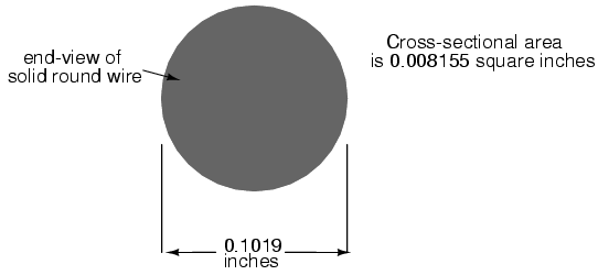
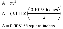
The wire cross-section picture shown above is, of course, not drawn to scale. The diameter is shown as being 0.1019 inches. Calculating the area of the cross-section with the formula Area = πr2, we get an area of 0.008155 square inches:
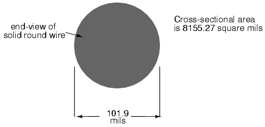
These are fairly small numbers to work with, so wire sizes are often expressed in measures of thousandths-of-an-inch, or mils. For the illustrated example, we would say that the diameter of the wire was 101.9 mils (0.1019 inch times 1000). We could also, if we wanted, express the area of the wire in the unit of square mils, calculating that value with the same circle-area formula, Area = πr2:
Calculating the Circular-mil Area of a Wire
However, electricians and others frequently concerned with wire size use another unit of area measurement tailored specifically for wire’s circular cross-section. This special unit is called the circular mil (sometimes abbreviated cmil). The sole purpose for having this special unit of measurement is to eliminate the need to invoke the factor π (3.1415927 . . .) in the formula for calculating area, plus the need to figure wire radiuswhen you’ve been given diameter. The formula for calculating the circular-mil area of a circular wire is very simple:

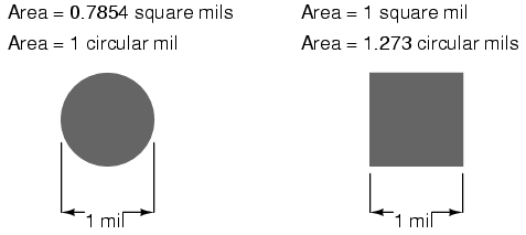
Because this is a unit of area measurement, the mathematical power of 2 is still in effect (doubling the width of a circle will always quadruple its area, no matter what units are used, or if the width of that circle is expressed in terms of radius or diameter). To illustrate the difference between measurements in square mils and measurements in circular mils, I will compare a circle with a square, showing the area of each shape in both unit measures:
And for another size of wire:
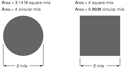
Obviously, the circle of a given diameter has less cross-sectional area than a square of width and height equal to the circle’s diameter: both units of area measurement reflect that. However, it should be clear that the unit of “square mil” is really tailored for the convenient determination of a square’s area, while “circular mil” is tailored for the convenient determination of a circle’s area: the respective formula for each is simpler to work with. It must be understood that both units are valid for measuring the area of a shape, no matter what shape that may be. The conversion between circular mils and square mils is a simple ratio: there are π (3.1415927 . . .) square mils to every 4 circular mils.
Measuring Cross-Sectional Wire Area with Gauge
Another measure of cross-sectional wire area is the gauge. The gauge scale is based on whole numbers rather than fractional or decimal inches. The larger the gauge number, the skinnier the wire; the smaller the gauge number, the fatter the wire. For those acquainted with shotguns, this inversely-proportional measurement scale should sound familiar.
The table at the end of this section equates gauge with inch diameter, circular mils, and square inches for solid wire. The larger sizes of wire reach an end of the common gauge scale (which naturally tops out at a value of 1), and are represented by a series of zeros. “3/0” is another way to represent “000,” and is pronounced “triple-ought.” Again, those acquainted with shotguns should recognize the terminology, strange as it may sound. To make matters even more confusing, there is more than one gauge “standard” in use around the world. For electrical conductor sizing, the American Wire Gauge (AWG), also known as the Brown and Sharpe (B&S) gauge, is the measurement system of choice. In Canada and Great Britain, the British Standard Wire Gauge (SWG) is the legal measurement system for electrical conductors. Other wire gauge systems exist in the world for classifying wire diameter, such as the Stubs steel wire gauge and the Steel Music Wire Gauge (MWG), but these measurement systems apply to non-electrical wire use.
The American Wire Gauge (AWG) measurement system, despite its oddities, was designed with a purpose: for every three steps in the gauge scale, wire area (and weight per unit length) approximately doubles. This is a handy rule to remember when making rough wire size estimations!
For very large wire sizes (fatter than 4/0), the wire gauge system is typically abandoned for cross-sectional area measurement in thousands of circular mils (MCM), borrowing the old Roman numeral “M” to denote a multiple of “thousand” in front of “CM” for “circular mils.” The following table of wire sizes does not show any sizes bigger than 4/0 gauge, because solid copper wire becomes impractical to handle at those sizes. Stranded wire construction is favored, instead.
For some high-current applications, conductor sizes beyond the practical size limit of round wire are required. In these instances, thick bars of solid metal called busbars are used as conductors. Busbars are usually made of copper or aluminum, and are most often uninsulated. They are physically supported away from whatever framework or structure is holding them by insulator standoff mounts. Although a square or rectangular cross-section is very common for busbar shape, other shapes are used as well. Cross-sectional area for busbars is typically rated in terms of circular mils (even for square and rectangular bars!), most likely for the convenience of being able to directly equate busbar size with round wire.
REVIEW:
- Electrons flow through large-diameter wires easier than small-diameter wires, due to the greater cross-sectional area they have in which to move.
- Rather than measure small wire sizes in inches, the unit of “mil” (1/1000 of an inch) is often employed.
- The cross-sectional area of a wire can be expressed in terms of square units (square inches or square mils), circular mils, or “gauge” scale.
- Calculating square-unit wire area for a circular wire involves the circle area formula:

- Calculating circular-mil wire area for a circular wire is much simpler, due to the fact that the unit of “circular mil” was sized just for this purpose: to eliminate the “pi” and the d/2 (radius) factors in the formula.

- There are π (3.1416) square mils for every 4 circular mils.
- The gauge system of wire sizing is based on whole numbers, larger numbers representing smaller-area wires and vice versa. Wires thicker than 1 gauge are represented by zeros: 0, 00, 000, and 0000 (spoken “single-ought,” “double-ought,” “triple-ought,” and “quadruple-ought.”
- Very large wire sizes are rated in thousands of circular mils (MCM’s), typical for busbars and wire sizes beyond 4/0.
- Busbars are solid bars of copper or aluminum used in high-current circuit construction. Connections made to busbars are usually welded or bolted, and the busbars are often bare (uninsulated), supported away from metal frames through the use of insulating standoffs.


