
3.8: Precision Potentiometer
- Page ID
- 2140

\( \newcommand{\vecs}[1]{\overset { \scriptstyle \rightharpoonup} {\mathbf{#1}} } \)
\( \newcommand{\vecd}[1]{\overset{-\!-\!\rightharpoonup}{\vphantom{a}\smash {#1}}} \)
\( \newcommand{\id}{\mathrm{id}}\) \( \newcommand{\Span}{\mathrm{span}}\)
( \newcommand{\kernel}{\mathrm{null}\,}\) \( \newcommand{\range}{\mathrm{range}\,}\)
\( \newcommand{\RealPart}{\mathrm{Re}}\) \( \newcommand{\ImaginaryPart}{\mathrm{Im}}\)
\( \newcommand{\Argument}{\mathrm{Arg}}\) \( \newcommand{\norm}[1]{\| #1 \|}\)
\( \newcommand{\inner}[2]{\langle #1, #2 \rangle}\)
\( \newcommand{\Span}{\mathrm{span}}\)
\( \newcommand{\id}{\mathrm{id}}\)
\( \newcommand{\Span}{\mathrm{span}}\)
\( \newcommand{\kernel}{\mathrm{null}\,}\)
\( \newcommand{\range}{\mathrm{range}\,}\)
\( \newcommand{\RealPart}{\mathrm{Re}}\)
\( \newcommand{\ImaginaryPart}{\mathrm{Im}}\)
\( \newcommand{\Argument}{\mathrm{Arg}}\)
\( \newcommand{\norm}[1]{\| #1 \|}\)
\( \newcommand{\inner}[2]{\langle #1, #2 \rangle}\)
\( \newcommand{\Span}{\mathrm{span}}\) \( \newcommand{\AA}{\unicode[.8,0]{x212B}}\)
\( \newcommand{\vectorA}[1]{\vec{#1}} % arrow\)
\( \newcommand{\vectorAt}[1]{\vec{\text{#1}}} % arrow\)
\( \newcommand{\vectorB}[1]{\overset { \scriptstyle \rightharpoonup} {\mathbf{#1}} } \)
\( \newcommand{\vectorC}[1]{\textbf{#1}} \)
\( \newcommand{\vectorD}[1]{\overrightarrow{#1}} \)
\( \newcommand{\vectorDt}[1]{\overrightarrow{\text{#1}}} \)
\( \newcommand{\vectE}[1]{\overset{-\!-\!\rightharpoonup}{\vphantom{a}\smash{\mathbf {#1}}}} \)
\( \newcommand{\vecs}[1]{\overset { \scriptstyle \rightharpoonup} {\mathbf{#1}} } \)
\( \newcommand{\vecd}[1]{\overset{-\!-\!\rightharpoonup}{\vphantom{a}\smash {#1}}} \)
\(\newcommand{\avec}{\mathbf a}\) \(\newcommand{\bvec}{\mathbf b}\) \(\newcommand{\cvec}{\mathbf c}\) \(\newcommand{\dvec}{\mathbf d}\) \(\newcommand{\dtil}{\widetilde{\mathbf d}}\) \(\newcommand{\evec}{\mathbf e}\) \(\newcommand{\fvec}{\mathbf f}\) \(\newcommand{\nvec}{\mathbf n}\) \(\newcommand{\pvec}{\mathbf p}\) \(\newcommand{\qvec}{\mathbf q}\) \(\newcommand{\svec}{\mathbf s}\) \(\newcommand{\tvec}{\mathbf t}\) \(\newcommand{\uvec}{\mathbf u}\) \(\newcommand{\vvec}{\mathbf v}\) \(\newcommand{\wvec}{\mathbf w}\) \(\newcommand{\xvec}{\mathbf x}\) \(\newcommand{\yvec}{\mathbf y}\) \(\newcommand{\zvec}{\mathbf z}\) \(\newcommand{\rvec}{\mathbf r}\) \(\newcommand{\mvec}{\mathbf m}\) \(\newcommand{\zerovec}{\mathbf 0}\) \(\newcommand{\onevec}{\mathbf 1}\) \(\newcommand{\real}{\mathbb R}\) \(\newcommand{\twovec}[2]{\left[\begin{array}{r}#1 \\ #2 \end{array}\right]}\) \(\newcommand{\ctwovec}[2]{\left[\begin{array}{c}#1 \\ #2 \end{array}\right]}\) \(\newcommand{\threevec}[3]{\left[\begin{array}{r}#1 \\ #2 \\ #3 \end{array}\right]}\) \(\newcommand{\cthreevec}[3]{\left[\begin{array}{c}#1 \\ #2 \\ #3 \end{array}\right]}\) \(\newcommand{\fourvec}[4]{\left[\begin{array}{r}#1 \\ #2 \\ #3 \\ #4 \end{array}\right]}\) \(\newcommand{\cfourvec}[4]{\left[\begin{array}{c}#1 \\ #2 \\ #3 \\ #4 \end{array}\right]}\) \(\newcommand{\fivevec}[5]{\left[\begin{array}{r}#1 \\ #2 \\ #3 \\ #4 \\ #5 \\ \end{array}\right]}\) \(\newcommand{\cfivevec}[5]{\left[\begin{array}{c}#1 \\ #2 \\ #3 \\ #4 \\ #5 \\ \end{array}\right]}\) \(\newcommand{\mattwo}[4]{\left[\begin{array}{rr}#1 \amp #2 \\ #3 \amp #4 \\ \end{array}\right]}\) \(\newcommand{\laspan}[1]{\text{Span}\{#1\}}\) \(\newcommand{\bcal}{\cal B}\) \(\newcommand{\ccal}{\cal C}\) \(\newcommand{\scal}{\cal S}\) \(\newcommand{\wcal}{\cal W}\) \(\newcommand{\ecal}{\cal E}\) \(\newcommand{\coords}[2]{\left\{#1\right\}_{#2}}\) \(\newcommand{\gray}[1]{\color{gray}{#1}}\) \(\newcommand{\lgray}[1]{\color{lightgray}{#1}}\) \(\newcommand{\rank}{\operatorname{rank}}\) \(\newcommand{\row}{\text{Row}}\) \(\newcommand{\col}{\text{Col}}\) \(\renewcommand{\row}{\text{Row}}\) \(\newcommand{\nul}{\text{Nul}}\) \(\newcommand{\var}{\text{Var}}\) \(\newcommand{\corr}{\text{corr}}\) \(\newcommand{\len}[1]{\left|#1\right|}\) \(\newcommand{\bbar}{\overline{\bvec}}\) \(\newcommand{\bhat}{\widehat{\bvec}}\) \(\newcommand{\bperp}{\bvec^\perp}\) \(\newcommand{\xhat}{\widehat{\xvec}}\) \(\newcommand{\vhat}{\widehat{\vvec}}\) \(\newcommand{\uhat}{\widehat{\uvec}}\) \(\newcommand{\what}{\widehat{\wvec}}\) \(\newcommand{\Sighat}{\widehat{\Sigma}}\) \(\newcommand{\lt}{<}\) \(\newcommand{\gt}{>}\) \(\newcommand{\amp}{&}\) \(\definecolor{fillinmathshade}{gray}{0.9}\)PARTS AND MATERIALS
- Two single-turn, linear-taper potentiometers, 5 kΩ each (Radio Shack catalog # 271-1714)
- One single-turn, linear-taper potentiometer, 50 kΩ (Radio Shack catalog # 271-1716)
- Plastic or metal mounting box
- Three “banana” jack style binding posts, or other terminal hardware, for connection to potentiometer circuit (Radio Shack catalog # 274-662 or equivalent)
This is a project useful to those who want a precision potentiometer without spending a lot of money. Ordinarily, multi-turn potentiometers are used to obtain precise voltage division ratios, but a cheaper alternative exists using multiple, single-turn (sometimes called “3/4-turn”) potentiometers connected together in a compound divider network.
Because this is a useful project, I recommend building it in permanent form using some form of project enclosure. Suppliers such as Radio Shack offer nice project boxes, but boxes purchased at a general hardware store are much less expensive, if a bit ugly. The ultimate in low cost for a new box are the plastic boxes sold as light switch and receptacle boxes for household electrical wiring.
“Banana” jacks allow for the temporary connection of test leads and jumper wires equipped with matching “banana” plug ends. Most multimeter test leads have this style of plug for insertion into the meter jacks. Banana plugs are so named because of their oblong appearance formed by spring steel strips, which maintain firm contact with the jack walls when inserted. Some banana jacks are called binding postsbecause they also allow plain wires to be firmly attached. Binding posts have screw-on sleeves that fit over a metal post. The sleeve is used as a nut to secure a wire wrapped around the post, or inserted through a perpendicular hole drilled through the post. A brief inspection of any binding post will clarify this verbal description.
CROSS-REFERENCES
Lessons In Electric Circuits, Volume 1, chapter 6: “Divider Circuits and Kirchhoff’s Laws”
LEARNING OBJECTIVES
- Soldering practice
- Potentiometer function and operation
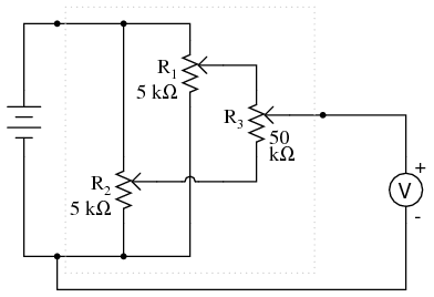
SCHEMATIC DIAGRAM
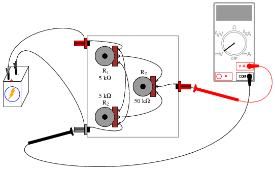
ILLUSTRATION
INSTRUCTIONS
It is essential that the connecting wires be soldered to the potentiometer terminals, not twisted or taped. Since potentiometer action is dependent on resistance, the resistance of all wiring connections must be carefully controlled to a bare minimum. Soldering ensures a condition of low resistance between joined conductors, and also provides very good mechanical strength for the connections.
When the circuit is assembled, connect a 6-volt battery to the outer two binding posts. Connect a voltmeter between the “wiper” post and the battery’s negative (-) terminal. This voltmeter will measure the “output” of the circuit.
The circuit works on the principle of compressed range: the voltage output range of this circuit available by adjusting potentiometer R3 is restricted between the limits set by potentiometers R1 and R2. In other words, if R1 and R2 were set to output 5 volts and 3 volts, respectively, from a 6-volt battery, the range of output voltages obtainable by adjusting R3 would be restricted from 3 to 5 volts for the full rotation of that potentiometer. If only a single potentiometer were used instead of this three-potentiometer circuit, full rotation would produce an output voltage from 0 volts to full battery voltage. The “range compression” afforded by this circuit allows for more precise voltage adjustment than would be normally obtainable using a single potentiometer.
Operating this potentiometer network is more complex than using a single potentiometer. To begin, turn the R3 potentiometer fully clockwise, so that its wiper is in the full “up” position as referenced to the schematic diagram (electrically “closest” to R1‘s wiper terminal). Adjust potentiometer R1 until the upper voltage limit is reached, as indicated by the voltmeter.
Turn the R3 potentiometer fully counter-clockwise, so that its wiper is in the full “down” position as referenced to the schematic diagram (electrically “closest” to R2‘s wiper terminal). Adjust potentiometer R2until the lower voltage limit is reached, as indicated by the voltmeter.
When either the R1 or the R2 potentiometer is adjusted, it interferes with the prior setting of the other. In other words, if R1 is initially adjusted to provide an upper voltage limit of 5.000 volts from a 6 volt battery, and then R2 is adjusted to provide some lower limit voltage different from what it was before, R1 will no longer be set to 5.000 volts.
To obtain precise upper and lower voltage limits, turn R3 fully clockwise to read and adjust the voltage of R1, then turn R3 fully counter-clockwise to read and adjust the voltage of R2, repeating as necessary.
Technically, this phenomenon of one adjustment affecting the other is known as interaction, and it is usually undesirable due to the extra effort required to set and re-set the adjustments. The reason that R1 and R2were specified as 10 times less resistance than R3 is to minimize this effect. If all three potentiometers were of equal resistance value, the interaction between R1 and R2 would be more severe, though manageable with patience. Bear in mind that the upper and lower voltage limits need not be set precisely in order for this circuit to achieve its goal of increased precision. So long as R3‘s adjustment range is compressed to some lesser value than full battery voltage, we will enjoy greater precision than a single potentiometer could provide.
Once the upper and lower voltage limits have been set, potentiometer R3 may be adjusted to produce an output voltage anywhere between those limits.