4.2: Transformer—Power Supply
- Page ID
- 1258

\( \newcommand{\vecs}[1]{\overset { \scriptstyle \rightharpoonup} {\mathbf{#1}} } \)
\( \newcommand{\vecd}[1]{\overset{-\!-\!\rightharpoonup}{\vphantom{a}\smash {#1}}} \)
\( \newcommand{\id}{\mathrm{id}}\) \( \newcommand{\Span}{\mathrm{span}}\)
( \newcommand{\kernel}{\mathrm{null}\,}\) \( \newcommand{\range}{\mathrm{range}\,}\)
\( \newcommand{\RealPart}{\mathrm{Re}}\) \( \newcommand{\ImaginaryPart}{\mathrm{Im}}\)
\( \newcommand{\Argument}{\mathrm{Arg}}\) \( \newcommand{\norm}[1]{\| #1 \|}\)
\( \newcommand{\inner}[2]{\langle #1, #2 \rangle}\)
\( \newcommand{\Span}{\mathrm{span}}\)
\( \newcommand{\id}{\mathrm{id}}\)
\( \newcommand{\Span}{\mathrm{span}}\)
\( \newcommand{\kernel}{\mathrm{null}\,}\)
\( \newcommand{\range}{\mathrm{range}\,}\)
\( \newcommand{\RealPart}{\mathrm{Re}}\)
\( \newcommand{\ImaginaryPart}{\mathrm{Im}}\)
\( \newcommand{\Argument}{\mathrm{Arg}}\)
\( \newcommand{\norm}[1]{\| #1 \|}\)
\( \newcommand{\inner}[2]{\langle #1, #2 \rangle}\)
\( \newcommand{\Span}{\mathrm{span}}\) \( \newcommand{\AA}{\unicode[.8,0]{x212B}}\)
\( \newcommand{\vectorA}[1]{\vec{#1}} % arrow\)
\( \newcommand{\vectorAt}[1]{\vec{\text{#1}}} % arrow\)
\( \newcommand{\vectorB}[1]{\overset { \scriptstyle \rightharpoonup} {\mathbf{#1}} } \)
\( \newcommand{\vectorC}[1]{\textbf{#1}} \)
\( \newcommand{\vectorD}[1]{\overrightarrow{#1}} \)
\( \newcommand{\vectorDt}[1]{\overrightarrow{\text{#1}}} \)
\( \newcommand{\vectE}[1]{\overset{-\!-\!\rightharpoonup}{\vphantom{a}\smash{\mathbf {#1}}}} \)
\( \newcommand{\vecs}[1]{\overset { \scriptstyle \rightharpoonup} {\mathbf{#1}} } \)
\( \newcommand{\vecd}[1]{\overset{-\!-\!\rightharpoonup}{\vphantom{a}\smash {#1}}} \)
\(\newcommand{\avec}{\mathbf a}\) \(\newcommand{\bvec}{\mathbf b}\) \(\newcommand{\cvec}{\mathbf c}\) \(\newcommand{\dvec}{\mathbf d}\) \(\newcommand{\dtil}{\widetilde{\mathbf d}}\) \(\newcommand{\evec}{\mathbf e}\) \(\newcommand{\fvec}{\mathbf f}\) \(\newcommand{\nvec}{\mathbf n}\) \(\newcommand{\pvec}{\mathbf p}\) \(\newcommand{\qvec}{\mathbf q}\) \(\newcommand{\svec}{\mathbf s}\) \(\newcommand{\tvec}{\mathbf t}\) \(\newcommand{\uvec}{\mathbf u}\) \(\newcommand{\vvec}{\mathbf v}\) \(\newcommand{\wvec}{\mathbf w}\) \(\newcommand{\xvec}{\mathbf x}\) \(\newcommand{\yvec}{\mathbf y}\) \(\newcommand{\zvec}{\mathbf z}\) \(\newcommand{\rvec}{\mathbf r}\) \(\newcommand{\mvec}{\mathbf m}\) \(\newcommand{\zerovec}{\mathbf 0}\) \(\newcommand{\onevec}{\mathbf 1}\) \(\newcommand{\real}{\mathbb R}\) \(\newcommand{\twovec}[2]{\left[\begin{array}{r}#1 \\ #2 \end{array}\right]}\) \(\newcommand{\ctwovec}[2]{\left[\begin{array}{c}#1 \\ #2 \end{array}\right]}\) \(\newcommand{\threevec}[3]{\left[\begin{array}{r}#1 \\ #2 \\ #3 \end{array}\right]}\) \(\newcommand{\cthreevec}[3]{\left[\begin{array}{c}#1 \\ #2 \\ #3 \end{array}\right]}\) \(\newcommand{\fourvec}[4]{\left[\begin{array}{r}#1 \\ #2 \\ #3 \\ #4 \end{array}\right]}\) \(\newcommand{\cfourvec}[4]{\left[\begin{array}{c}#1 \\ #2 \\ #3 \\ #4 \end{array}\right]}\) \(\newcommand{\fivevec}[5]{\left[\begin{array}{r}#1 \\ #2 \\ #3 \\ #4 \\ #5 \\ \end{array}\right]}\) \(\newcommand{\cfivevec}[5]{\left[\begin{array}{c}#1 \\ #2 \\ #3 \\ #4 \\ #5 \\ \end{array}\right]}\) \(\newcommand{\mattwo}[4]{\left[\begin{array}{rr}#1 \amp #2 \\ #3 \amp #4 \\ \end{array}\right]}\) \(\newcommand{\laspan}[1]{\text{Span}\{#1\}}\) \(\newcommand{\bcal}{\cal B}\) \(\newcommand{\ccal}{\cal C}\) \(\newcommand{\scal}{\cal S}\) \(\newcommand{\wcal}{\cal W}\) \(\newcommand{\ecal}{\cal E}\) \(\newcommand{\coords}[2]{\left\{#1\right\}_{#2}}\) \(\newcommand{\gray}[1]{\color{gray}{#1}}\) \(\newcommand{\lgray}[1]{\color{lightgray}{#1}}\) \(\newcommand{\rank}{\operatorname{rank}}\) \(\newcommand{\row}{\text{Row}}\) \(\newcommand{\col}{\text{Col}}\) \(\renewcommand{\row}{\text{Row}}\) \(\newcommand{\nul}{\text{Nul}}\) \(\newcommand{\var}{\text{Var}}\) \(\newcommand{\corr}{\text{corr}}\) \(\newcommand{\len}[1]{\left|#1\right|}\) \(\newcommand{\bbar}{\overline{\bvec}}\) \(\newcommand{\bhat}{\widehat{\bvec}}\) \(\newcommand{\bperp}{\bvec^\perp}\) \(\newcommand{\xhat}{\widehat{\xvec}}\) \(\newcommand{\vhat}{\widehat{\vvec}}\) \(\newcommand{\uhat}{\widehat{\uvec}}\) \(\newcommand{\what}{\widehat{\wvec}}\) \(\newcommand{\Sighat}{\widehat{\Sigma}}\) \(\newcommand{\lt}{<}\) \(\newcommand{\gt}{>}\) \(\newcommand{\amp}{&}\) \(\definecolor{fillinmathshade}{gray}{0.9}\)PARTS AND MATERIALS
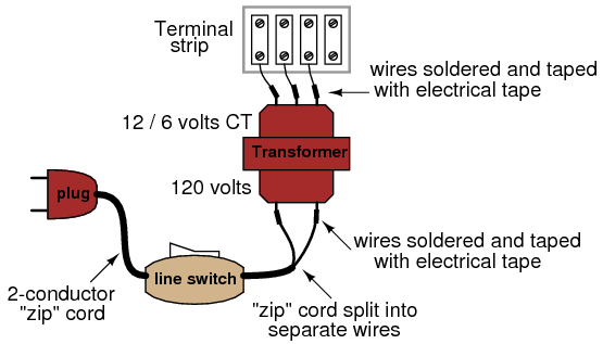
- Power transformer, 120VAC step-down to 12VAC, with the center-tapped secondary winding (Radio Shack catalog # 273-1365, 273-1352, or 273-1511).
- Terminal strip with at least three terminals.
- Household wall-socket power plug and cord.
- Line cord switch.
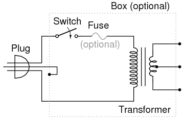
- Box (optional).
- Fuse and fuse holder (optional).
Power transformers may be obtained from old radios, which can usually be obtained from a thrift store for a few dollars (or less!). The radio would also provide the power cord and plug necessary for this project. Line cord switches may be obtained from a hardware store. If you want to be absolutely sure what kind of transformer you’re getting, though, you should purchase one from an electronics supply store.
If you decide to equip your power supply with a fuse, be sure to get a slow-acting, or slow-blow fuse. Transformers may draw high “surge” currents when initially connected to an AC source, and these transient currents will blow a fast-acting fuse. Determine the proper current rating of the fuse by dividing the transformer’s “VA” rating by 120 volts: in other words, calculate the full allowable primary winding current and size the fuse accordingly.
CROSS-REFERENCES
Lessons In Electric Circuits, Volume 2, chapter 1: “Basic AC Theory”
Lessons In Electric Circuits, Volume 2, chapter 9: “Transformers”
LEARNING OBJECTIVES
- Transformer voltage step-down behavior.
- Purpose of tapped windings.
- Safe wiring techniques for power cords.
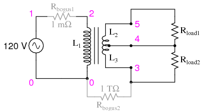
SCHEMATIC DIAGRAM
ILLUSTRATION
INSTRUCTIONS
Warning! This project involves the use of dangerous voltages. You must make sure all high-voltage (120-volt household power) conductors are safely insulated from accidental contact. No bare wires should be seen anywhere on the “primary” side of the transformer circuit. Be sure to solder all wire connections so that they’re secure, and use real electrical tape (not duct tape, scotch tape, packing tape, or any other kind!) to insulate your soldered connections.
If you wish to enclose the transformer inside of a box, you may use an electrical “junction” box, obtained from a hardware store or electrical supply house. If the enclosure used is metal rather than plastic, a three-prong plug should be used, with the “ground” prong (the longest one on the plug) connected directly to the metal case for maximum safety.
Before plugging the plug into a wall socket, do a safety check with an ohmmeter. With the line switch in the “on” position, measure resistance between either plug prong and the transformer case. There should be infinite (maximum) resistance. If the meter registers continuity (some resistance value less than infinity), then you have a “short” between one of the power conductors and the case, which is dangerous!
Next, check the transformer windings themselves for continuity. With the line switch in the “on” position, there should be a small amount of resistance between the two plug prongs. When the switch is turned “off,” the resistance indication should increase to infinity (open circuit—no continuity). Measure resistance between pairs of wires on the secondary side. These secondary windings should register much lower resistance than the primary. Why is this?
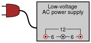
Plug the cord into a wall socket and turn the switch on. You should be able to measure AC voltage at the secondary side of the transformer, between pairs of terminals. Between two of these terminals, you should measure about 12 volts. Between either of these two terminals and the third terminal, you should measure half that. This third wire is the “center-tap” wire of the secondary winding.
It would be advisable to keep this project assembled for use in powering other experiments shown in this book. From here on, I will designate this “low-voltage AC power supply” using this illustration:
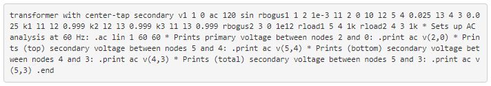
COMPUTER SIMULATION