
4.17: Signal Coupling
- Page ID
- 2168

\( \newcommand{\vecs}[1]{\overset { \scriptstyle \rightharpoonup} {\mathbf{#1}} } \)
\( \newcommand{\vecd}[1]{\overset{-\!-\!\rightharpoonup}{\vphantom{a}\smash {#1}}} \)
\( \newcommand{\id}{\mathrm{id}}\) \( \newcommand{\Span}{\mathrm{span}}\)
( \newcommand{\kernel}{\mathrm{null}\,}\) \( \newcommand{\range}{\mathrm{range}\,}\)
\( \newcommand{\RealPart}{\mathrm{Re}}\) \( \newcommand{\ImaginaryPart}{\mathrm{Im}}\)
\( \newcommand{\Argument}{\mathrm{Arg}}\) \( \newcommand{\norm}[1]{\| #1 \|}\)
\( \newcommand{\inner}[2]{\langle #1, #2 \rangle}\)
\( \newcommand{\Span}{\mathrm{span}}\)
\( \newcommand{\id}{\mathrm{id}}\)
\( \newcommand{\Span}{\mathrm{span}}\)
\( \newcommand{\kernel}{\mathrm{null}\,}\)
\( \newcommand{\range}{\mathrm{range}\,}\)
\( \newcommand{\RealPart}{\mathrm{Re}}\)
\( \newcommand{\ImaginaryPart}{\mathrm{Im}}\)
\( \newcommand{\Argument}{\mathrm{Arg}}\)
\( \newcommand{\norm}[1]{\| #1 \|}\)
\( \newcommand{\inner}[2]{\langle #1, #2 \rangle}\)
\( \newcommand{\Span}{\mathrm{span}}\) \( \newcommand{\AA}{\unicode[.8,0]{x212B}}\)
\( \newcommand{\vectorA}[1]{\vec{#1}} % arrow\)
\( \newcommand{\vectorAt}[1]{\vec{\text{#1}}} % arrow\)
\( \newcommand{\vectorB}[1]{\overset { \scriptstyle \rightharpoonup} {\mathbf{#1}} } \)
\( \newcommand{\vectorC}[1]{\textbf{#1}} \)
\( \newcommand{\vectorD}[1]{\overrightarrow{#1}} \)
\( \newcommand{\vectorDt}[1]{\overrightarrow{\text{#1}}} \)
\( \newcommand{\vectE}[1]{\overset{-\!-\!\rightharpoonup}{\vphantom{a}\smash{\mathbf {#1}}}} \)
\( \newcommand{\vecs}[1]{\overset { \scriptstyle \rightharpoonup} {\mathbf{#1}} } \)
\( \newcommand{\vecd}[1]{\overset{-\!-\!\rightharpoonup}{\vphantom{a}\smash {#1}}} \)
\(\newcommand{\avec}{\mathbf a}\) \(\newcommand{\bvec}{\mathbf b}\) \(\newcommand{\cvec}{\mathbf c}\) \(\newcommand{\dvec}{\mathbf d}\) \(\newcommand{\dtil}{\widetilde{\mathbf d}}\) \(\newcommand{\evec}{\mathbf e}\) \(\newcommand{\fvec}{\mathbf f}\) \(\newcommand{\nvec}{\mathbf n}\) \(\newcommand{\pvec}{\mathbf p}\) \(\newcommand{\qvec}{\mathbf q}\) \(\newcommand{\svec}{\mathbf s}\) \(\newcommand{\tvec}{\mathbf t}\) \(\newcommand{\uvec}{\mathbf u}\) \(\newcommand{\vvec}{\mathbf v}\) \(\newcommand{\wvec}{\mathbf w}\) \(\newcommand{\xvec}{\mathbf x}\) \(\newcommand{\yvec}{\mathbf y}\) \(\newcommand{\zvec}{\mathbf z}\) \(\newcommand{\rvec}{\mathbf r}\) \(\newcommand{\mvec}{\mathbf m}\) \(\newcommand{\zerovec}{\mathbf 0}\) \(\newcommand{\onevec}{\mathbf 1}\) \(\newcommand{\real}{\mathbb R}\) \(\newcommand{\twovec}[2]{\left[\begin{array}{r}#1 \\ #2 \end{array}\right]}\) \(\newcommand{\ctwovec}[2]{\left[\begin{array}{c}#1 \\ #2 \end{array}\right]}\) \(\newcommand{\threevec}[3]{\left[\begin{array}{r}#1 \\ #2 \\ #3 \end{array}\right]}\) \(\newcommand{\cthreevec}[3]{\left[\begin{array}{c}#1 \\ #2 \\ #3 \end{array}\right]}\) \(\newcommand{\fourvec}[4]{\left[\begin{array}{r}#1 \\ #2 \\ #3 \\ #4 \end{array}\right]}\) \(\newcommand{\cfourvec}[4]{\left[\begin{array}{c}#1 \\ #2 \\ #3 \\ #4 \end{array}\right]}\) \(\newcommand{\fivevec}[5]{\left[\begin{array}{r}#1 \\ #2 \\ #3 \\ #4 \\ #5 \\ \end{array}\right]}\) \(\newcommand{\cfivevec}[5]{\left[\begin{array}{c}#1 \\ #2 \\ #3 \\ #4 \\ #5 \\ \end{array}\right]}\) \(\newcommand{\mattwo}[4]{\left[\begin{array}{rr}#1 \amp #2 \\ #3 \amp #4 \\ \end{array}\right]}\) \(\newcommand{\laspan}[1]{\text{Span}\{#1\}}\) \(\newcommand{\bcal}{\cal B}\) \(\newcommand{\ccal}{\cal C}\) \(\newcommand{\scal}{\cal S}\) \(\newcommand{\wcal}{\cal W}\) \(\newcommand{\ecal}{\cal E}\) \(\newcommand{\coords}[2]{\left\{#1\right\}_{#2}}\) \(\newcommand{\gray}[1]{\color{gray}{#1}}\) \(\newcommand{\lgray}[1]{\color{lightgray}{#1}}\) \(\newcommand{\rank}{\operatorname{rank}}\) \(\newcommand{\row}{\text{Row}}\) \(\newcommand{\col}{\text{Col}}\) \(\renewcommand{\row}{\text{Row}}\) \(\newcommand{\nul}{\text{Nul}}\) \(\newcommand{\var}{\text{Var}}\) \(\newcommand{\corr}{\text{corr}}\) \(\newcommand{\len}[1]{\left|#1\right|}\) \(\newcommand{\bbar}{\overline{\bvec}}\) \(\newcommand{\bhat}{\widehat{\bvec}}\) \(\newcommand{\bperp}{\bvec^\perp}\) \(\newcommand{\xhat}{\widehat{\xvec}}\) \(\newcommand{\vhat}{\widehat{\vvec}}\) \(\newcommand{\uhat}{\widehat{\uvec}}\) \(\newcommand{\what}{\widehat{\wvec}}\) \(\newcommand{\Sighat}{\widehat{\Sigma}}\) \(\newcommand{\lt}{<}\) \(\newcommand{\gt}{>}\) \(\newcommand{\amp}{&}\) \(\definecolor{fillinmathshade}{gray}{0.9}\)PARTS AND MATERIALS
- 6 volt battery
- One capacitor, 0.22 µF (Radio Shack catalog # 272-1070 or equivalent)
- One capacitor, 0.047 µF (Radio Shack catalog # 272-134 or equivalent)
- Small “hobby” motor, permanent-magnet type (Radio Shack catalog # 273-223 or equivalent)
- Audio detector with headphones
- Length of telephone cable, several feet long (Radio Shack catalog # 278-872)
Telephone cable is also available from hardware stores. Any unshielded multiconductor cable will suffice for this experiment. Cables with thin conductors (telephone cable is typically 24-gauge) produce a more pronounced effect.
CROSS-REFERENCES
Lessons In Electric Circuits, Volume 2, chapter 7: “Mixed-Frequency AC Signals”
Lessons In Electric Circuits, Volume 2, chapter 8: “Filters”
LEARNING OBJECTIVES
- How to “couple” AC signals and block DC signals to a measuring instrument
- How stray coupling happens in cables
- Techniques to minimize inter-cable coupling
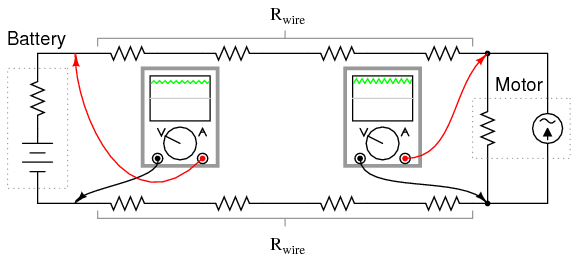
SCHEMATIC DIAGRAM
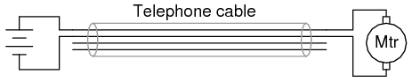
ILLUSTRATION
INSTRUCTIONS
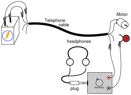
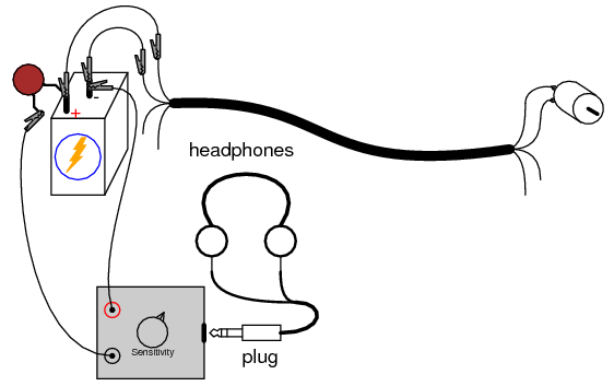
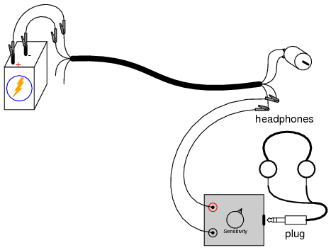
Connect the motor to the battery using two of the telephone cable’s four conductors. The motor should run, as expected. Now, connect the audio signal detector across the motor terminals, with the 0.047 µF capacitor in series, like this:
You should be able to hear a “buzz” or “whine” in the headphones, representing the AC “noise” voltage produced by the motor as the brushes make and break contact with the rotating commutator bars. The purpose of the series capacitor is to act as a high-pass filter so that the detector only receives the AC voltage across the motor’s terminals, not any DC voltage. This is precisely how oscilloscopes provide an “AC coupling” feature for measuring the AC content of a signal without any DC bias voltage: a capacitor is connected in series with one test probe.
Ideally, one would expect nothing but pure DC voltage at the motor’s terminals, because the motor is connected directly in parallel with the battery. Since the motor’s terminals are electrically common with the respective terminals of the battery, and the battery’s nature is to maintain a constant DC voltage, nothing but DC voltage should appear at the motor terminals, right? Well, because of resistance internal to the battery and along the conductor lengths, current pulses drawn by the motor produce oscillating voltage “dips” at the motor terminals, causing the AC “noise” heard by the detector:
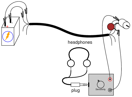
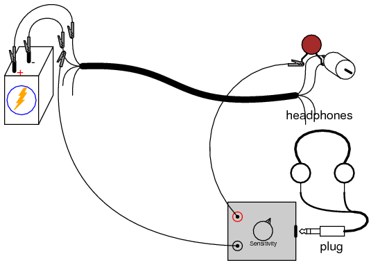
Use the audio detector to measure “noise” voltage directly across the battery. Since the AC noise is produced in this circuit by pulsating voltage drops along stray resistances, the less resistance we measure across, the less noise voltage we should detect:
You may also measure noise voltage dropped along either of the telephone cable conductors supplying power to the motor, by connecting the audio detector between both ends of a single cable conductor. The noise detected here originates from current pulses through the resistance of the wire:
Now that we have established how AC noise is created and distributed in this circuit, let’s explore how it is coupled to adjacent wires in the cable. Use the audio detector to measure voltage between one of the motor terminals and one of the unused wires in the telephone cable. The 0.047 µF capacitor is not needed in this exercise, because there is no DC voltage between these points for the detector to detect anyway:
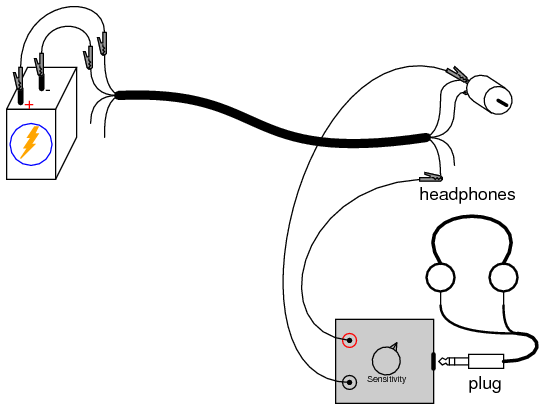
The noise voltage detected here is due to stray capacitance between adjacent cable conductors creating an AC current “path” between the wires. Remember that no current actually goes through a capacitance, but the alternate charging and discharging action of a capacitance, whether it be intentional or unintentional, provides alternating current a pathway of sorts.
If we were to try and conduct a voltage signal between one of the unused wires and a point common with the motor, that signal would become tainted with noise voltage from the motor. This could be quite detrimental, depending on how much noise was coupled between the two circuits and how sensitive one circuit was to the other’s noise. Since the primary coupling phenomenon in this circuit is capacitive in nature, higher-frequency noise voltages are more strongly coupled than lower-frequency noise voltages.
If the additional signal was a DC signal, with no AC expected in it, we could mitigate the problem of coupled noise by “decoupling” the AC noise with a relatively large capacitor connected across the DC signal’s conductors. Use the 0.22 µF capacitor for this purpose, as shown:
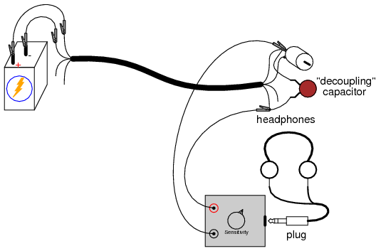
The decoupling capacitor acts as a practical short-circuit to any AC noise voltage, while not affecting DC voltage signals between those two points at all. So long as the decoupling capacitor value is significantly larger than the stray “coupling” capacitance between the cable’s conductors, the AC noise voltage will be held to a minimum.
Another way of minimizing coupled noise in a cable is to avoid having two circuits share a common conductor. To illustrate, connect the audio detector between the two unused wires and listen for a noise signal:
There should be far less noise detected between any two of the unused conductors than between one unused conductor and one used in the motor circuit. The reason for this drastic reduction in noise is that stray capacitance between cable conductors tends to couple the same noise voltage to both of the unused conductors in approximately equal proportions. Thus, when measuring voltage between those two conductors, the detector only “sees” the difference between two approximately identical noise signals.