
7.6: LED Sequencer
- Page ID
- 1283

\( \newcommand{\vecs}[1]{\overset { \scriptstyle \rightharpoonup} {\mathbf{#1}} } \)
\( \newcommand{\vecd}[1]{\overset{-\!-\!\rightharpoonup}{\vphantom{a}\smash {#1}}} \)
\( \newcommand{\dsum}{\displaystyle\sum\limits} \)
\( \newcommand{\dint}{\displaystyle\int\limits} \)
\( \newcommand{\dlim}{\displaystyle\lim\limits} \)
\( \newcommand{\id}{\mathrm{id}}\) \( \newcommand{\Span}{\mathrm{span}}\)
( \newcommand{\kernel}{\mathrm{null}\,}\) \( \newcommand{\range}{\mathrm{range}\,}\)
\( \newcommand{\RealPart}{\mathrm{Re}}\) \( \newcommand{\ImaginaryPart}{\mathrm{Im}}\)
\( \newcommand{\Argument}{\mathrm{Arg}}\) \( \newcommand{\norm}[1]{\| #1 \|}\)
\( \newcommand{\inner}[2]{\langle #1, #2 \rangle}\)
\( \newcommand{\Span}{\mathrm{span}}\)
\( \newcommand{\id}{\mathrm{id}}\)
\( \newcommand{\Span}{\mathrm{span}}\)
\( \newcommand{\kernel}{\mathrm{null}\,}\)
\( \newcommand{\range}{\mathrm{range}\,}\)
\( \newcommand{\RealPart}{\mathrm{Re}}\)
\( \newcommand{\ImaginaryPart}{\mathrm{Im}}\)
\( \newcommand{\Argument}{\mathrm{Arg}}\)
\( \newcommand{\norm}[1]{\| #1 \|}\)
\( \newcommand{\inner}[2]{\langle #1, #2 \rangle}\)
\( \newcommand{\Span}{\mathrm{span}}\) \( \newcommand{\AA}{\unicode[.8,0]{x212B}}\)
\( \newcommand{\vectorA}[1]{\vec{#1}} % arrow\)
\( \newcommand{\vectorAt}[1]{\vec{\text{#1}}} % arrow\)
\( \newcommand{\vectorB}[1]{\overset { \scriptstyle \rightharpoonup} {\mathbf{#1}} } \)
\( \newcommand{\vectorC}[1]{\textbf{#1}} \)
\( \newcommand{\vectorD}[1]{\overrightarrow{#1}} \)
\( \newcommand{\vectorDt}[1]{\overrightarrow{\text{#1}}} \)
\( \newcommand{\vectE}[1]{\overset{-\!-\!\rightharpoonup}{\vphantom{a}\smash{\mathbf {#1}}}} \)
\( \newcommand{\vecs}[1]{\overset { \scriptstyle \rightharpoonup} {\mathbf{#1}} } \)
\(\newcommand{\longvect}{\overrightarrow}\)
\( \newcommand{\vecd}[1]{\overset{-\!-\!\rightharpoonup}{\vphantom{a}\smash {#1}}} \)
\(\newcommand{\avec}{\mathbf a}\) \(\newcommand{\bvec}{\mathbf b}\) \(\newcommand{\cvec}{\mathbf c}\) \(\newcommand{\dvec}{\mathbf d}\) \(\newcommand{\dtil}{\widetilde{\mathbf d}}\) \(\newcommand{\evec}{\mathbf e}\) \(\newcommand{\fvec}{\mathbf f}\) \(\newcommand{\nvec}{\mathbf n}\) \(\newcommand{\pvec}{\mathbf p}\) \(\newcommand{\qvec}{\mathbf q}\) \(\newcommand{\svec}{\mathbf s}\) \(\newcommand{\tvec}{\mathbf t}\) \(\newcommand{\uvec}{\mathbf u}\) \(\newcommand{\vvec}{\mathbf v}\) \(\newcommand{\wvec}{\mathbf w}\) \(\newcommand{\xvec}{\mathbf x}\) \(\newcommand{\yvec}{\mathbf y}\) \(\newcommand{\zvec}{\mathbf z}\) \(\newcommand{\rvec}{\mathbf r}\) \(\newcommand{\mvec}{\mathbf m}\) \(\newcommand{\zerovec}{\mathbf 0}\) \(\newcommand{\onevec}{\mathbf 1}\) \(\newcommand{\real}{\mathbb R}\) \(\newcommand{\twovec}[2]{\left[\begin{array}{r}#1 \\ #2 \end{array}\right]}\) \(\newcommand{\ctwovec}[2]{\left[\begin{array}{c}#1 \\ #2 \end{array}\right]}\) \(\newcommand{\threevec}[3]{\left[\begin{array}{r}#1 \\ #2 \\ #3 \end{array}\right]}\) \(\newcommand{\cthreevec}[3]{\left[\begin{array}{c}#1 \\ #2 \\ #3 \end{array}\right]}\) \(\newcommand{\fourvec}[4]{\left[\begin{array}{r}#1 \\ #2 \\ #3 \\ #4 \end{array}\right]}\) \(\newcommand{\cfourvec}[4]{\left[\begin{array}{c}#1 \\ #2 \\ #3 \\ #4 \end{array}\right]}\) \(\newcommand{\fivevec}[5]{\left[\begin{array}{r}#1 \\ #2 \\ #3 \\ #4 \\ #5 \\ \end{array}\right]}\) \(\newcommand{\cfivevec}[5]{\left[\begin{array}{c}#1 \\ #2 \\ #3 \\ #4 \\ #5 \\ \end{array}\right]}\) \(\newcommand{\mattwo}[4]{\left[\begin{array}{rr}#1 \amp #2 \\ #3 \amp #4 \\ \end{array}\right]}\) \(\newcommand{\laspan}[1]{\text{Span}\{#1\}}\) \(\newcommand{\bcal}{\cal B}\) \(\newcommand{\ccal}{\cal C}\) \(\newcommand{\scal}{\cal S}\) \(\newcommand{\wcal}{\cal W}\) \(\newcommand{\ecal}{\cal E}\) \(\newcommand{\coords}[2]{\left\{#1\right\}_{#2}}\) \(\newcommand{\gray}[1]{\color{gray}{#1}}\) \(\newcommand{\lgray}[1]{\color{lightgray}{#1}}\) \(\newcommand{\rank}{\operatorname{rank}}\) \(\newcommand{\row}{\text{Row}}\) \(\newcommand{\col}{\text{Col}}\) \(\renewcommand{\row}{\text{Row}}\) \(\newcommand{\nul}{\text{Nul}}\) \(\newcommand{\var}{\text{Var}}\) \(\newcommand{\corr}{\text{corr}}\) \(\newcommand{\len}[1]{\left|#1\right|}\) \(\newcommand{\bbar}{\overline{\bvec}}\) \(\newcommand{\bhat}{\widehat{\bvec}}\) \(\newcommand{\bperp}{\bvec^\perp}\) \(\newcommand{\xhat}{\widehat{\xvec}}\) \(\newcommand{\vhat}{\widehat{\vvec}}\) \(\newcommand{\uhat}{\widehat{\uvec}}\) \(\newcommand{\what}{\widehat{\wvec}}\) \(\newcommand{\Sighat}{\widehat{\Sigma}}\) \(\newcommand{\lt}{<}\) \(\newcommand{\gt}{>}\) \(\newcommand{\amp}{&}\) \(\definecolor{fillinmathshade}{gray}{0.9}\)PARTS AND MATERIALS
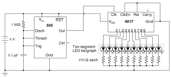
- 4017 decade counter/divider (Radio Shack catalog # 276-2417)
- 555 timer IC (Radio Shack catalog # 276-1723)
- Ten-segment bargraph LED (Radio Shack catalog # 276-081)
- One SPST switch
- One 6 volt battery
- 10 kΩ resistor
- 1 MΩ resistor
- 0.1 µF capacitor (Radio Shack catalog # 272-135 or equivalent)
- Coupling capacitor, 0.047 to 0.001 µF
- Ten 470 Ω resistors
- Audio detector with headphones
Caution! The 4017 IC is CMOS, and therefore sensitive to static electricity!
Any single-pole, single-throw switch is adequate. A household light switch will work fine and is readily available at any hardware store.
The audio detector will be used to assess signal frequency. If you have access to an oscilloscope, the audio detector is unnecessary.
CROSS-REFERENCES
Lessons In Electric Circuits, Volume 4, chapter 3: “Logic Gates”
Lessons In Electric Circuits, Volume 4, chapter 4: “Switches”
Lessons In Electric Circuits, Volume 4, chapter 11: “Counters”
LEARNING OBJECTIVES
- Use of a 555 timer circuit to produce “clock” pulses (astable multivibrator)
- Use of a 4017 decade counter/divider circuit to produce a sequence of pulses
- Use of a 4017 decade counter/divider circuit for frequency division
- Using a frequency divider and timepiece (watch) to measure frequency
- Purpose of a “pulldown” resistor
- Learn the effects of switch contact “bounce” on digital circuits
- Use of a 555 timer circuit to “debounce” a mechanical switch (monostable multivibrator)
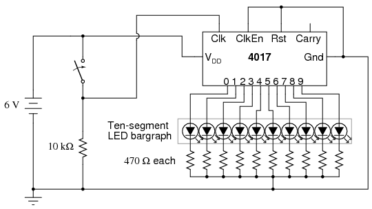
SCHEMATIC DIAGRAM
ILLUSTRATION
INSTRUCTIONS
The model 4017 integrated circuit is a CMOS counter with ten output terminals. One of these ten terminals will be in a “high” state at any given time, with all others being “low,” giving a “one-of-ten” output sequence. If low-to-high voltage pulses are applied to the “clock” (Clk) terminal of the 4017, it will increment its count, forcing the next output into a “high” state.
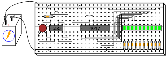
With a 555 timer connected as an astable multivibrator (oscillator) of low frequency, the 4017 will cycle through its ten-count sequence, lighting up each LED, one at a time, and “recycling” back to the first LED. The result is a visually pleasing sequence of flashing lights. Feel free to experiment with resistor and capacitor values on the 555 timer to create different flash rates.
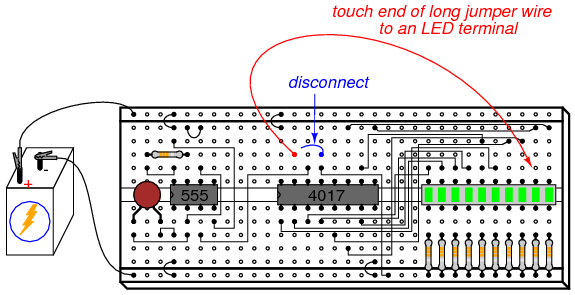
Try disconnecting the jumper wire leading from the 4017’s “Clock” terminal (pin #14) to the 555’s “Output” terminal (pin #3) where it connects to the 555 timer chip, and hold its end in your hand. If there is sufficient 60 Hz power-line “noise” around you, the 4017 will detect it as a fast clock signal, causing the LEDs to blink very rapidly.
Two terminals on the 4017 chip, “Reset” and “Clock Enable,” are maintained in a “low” state by means of a connection to the negative side of the battery (ground). This is necessary if the chip is to count freely. If the “Reset” terminal is made “high,” the 4017’s output will be reset back to 0 (pin #3 “high,” all other output pins “low”). If the “Clock Enable” is made “high,” the chip will stop responding to the clock signal and pause in its counting sequence.
If the 4017’s “Reset” terminal is connected to one of its ten output terminals, its counting sequence will be cut short or truncated. You may experiment with this by disconnecting the “Reset” terminal from ground, then connecting a long jumper wire to the “Reset” terminal for easy connection to the outputs at the ten-segment LED bargraph. Notice how many (or how few) LEDs light up with the “Reset” connected to any one of the outputs:
Counters such as the 4017 may be used as digital frequency dividers, to take a clock signal and produce a pulse occurring at some integer factor of the clock frequency. For example, if the clock signal from the 555 timer is 200 Hz, and the 4017 is configured for a full-count sequence (the “Reset” terminal connected to ground, giving a full, ten-step count), a signal with a period ten times as long (20 Hz) will be present at any of the 4017’s output terminals. In other words, each output terminal will cycle once for every ten cycles of the clock signal: a frequency ten times as slow.
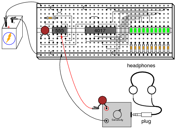
To experiment with this principle, connect your audio detector between output 0 (pin #3) of the 4017 and ground, through a very small capacitor (0.047 µF to 0.001 µF). The capacitor is used for “coupling” AC signals only, to that you may audibly detect pulses without placing a DC (resistive) load on the counter chip output. With the 4017 “Reset” terminal grounded, you will have a full-count sequence, and you will hear a “click” in the headphones every time the “0” LED lights up, corresponding to 1/10 of the 555’s actual output frequency:
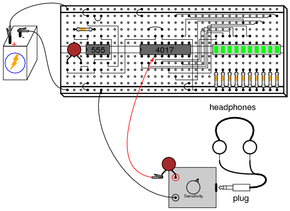
In fact, knowing this mathematical relationship between clicks heard in the headphone and the clock frequency allows us to measure the clock frequency to a fair degree of precision. Using a stopwatch or other timepiece, count the number of clicks heard in one full minute while connected to the 4017’s “0” output. Using a 1 MΩ resistor and 0.1 µF capacitor in the 555 timing circuit, and a power supply voltage of 13 volts (instead of 6), I counted 79 clicks in one minute from my circuit. Your circuit may produce slightly different results. Multiply the number of pulses counted at the “0” output by 10 to obtain the number of cycles produced by the 555 timer during that same time (my circuit: 79 x 10 = 790 cycles). Divide this number by 60 to obtain the number of timer cycles elapsed in each second (my circuit: 790/60 = 13.17). This final figure is the clock frequency in Hz.
Now, leaving one test probe of the audio detector connected to ground, take the other test probe (the one with the coupling capacitor connected in series) and connect it to pin #3 of the 555 timer. The buzzing you hear is the undivided clock frequency:
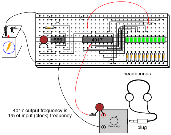
By connecting the 4017’s “Reset” terminal to one of the output terminals, a truncated sequence will result. If we are using the 4017 as a frequency divider, this means the output frequency will be a different factor of the clock frequency: 1/9, 1/8, 1/7, 1/6, 1/5, 1/4, 1/3, or 1/2, depending on which output terminal we connect the “Reset” jumper wire to. Re-connect the audio detector test probe to output “0” of the 4017 (pin #3), and connect the “Reset” terminal jumper to the sixth LED from the left on the bargraph. This should produce a 1/5 frequency division ratio:
Counting the number of clicks heard in one minute again, you should obtain a number approximately twice as large as what was counted with the 4017 configured for a 1/10 ratio, because 1/5 is twice as large a ratio as 1/10. If you do not obtain a count that is exactly twice what you obtained before, it is because of error inherent to the method of counting cycles: coordinating your sense of hearing with the display of a stopwatch or other time-keeping device.
Try replacing the 1 MΩ timing resistor in the 555 circuit with one of greatly lesser value, such as 10 kΩ. This will increase the clock frequency driving the 4017 chip. Use the audio detector to listen to the divided frequency at pin #3 of the 4017, noting the different tones produced as you move the “Reset” jumper wire to different outputs, creating different frequency division ratios. See if you can produce octaves by dividing the original frequency by 2, then by 4, and then by 8 (each descending octave represents one-half the previous frequency). Octaves are readily distinguished from other divided frequencies by their similar pitches to the original tone.
A final lesson that may be learned from this circuit is that of switch contact “bounce.” For this, you will need a switch to provide clock signals to the 4017 chip, instead of the 555 timer. Re-connect the “Reset” jumper wire to ground to enable a full ten-step count sequence, and disconnect the 555’s output from the 4017’s “Clock” input terminal. Connect a switch in series with a 10 kΩ pulldown resistor, and connect this assembly to the 4017 “Clock” input as shown:
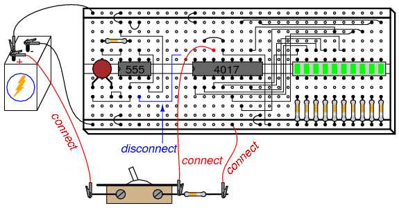
The purpose of a “pulldown” resistor is to provide a definite “low” logic state when the switch contact opens. Without this resistor in place, the 4017’s “Clock” input wire would be floating whenever the switch contact was opened, leaving it susceptible to interference from stray static voltages or electrical “noise,” either one capable of making the 4017 count randomly. With the pulldown resistor in place, the 4017’s “Clock” input will have a definite, albeit resistive, connection to ground, providing a stable “low” logic state that precludes any interference from static electricity or “noise” coupled from nearby AC circuit wiring.
Actuate the switch on and off, noting the action of the LEDs. With each off-to-on switch transition, the 4017 should increment once in its count. However, you may notice some strange behavior: sometimes, the LED sequence will “skip” one or even several steps with a single switch closure. Why is this? It is due to very rapid, mechanical “bouncing” of the switch contacts. When two metallic contacts are brought together rapidly as does happen inside most switches, there will be an elastic collision. This collision results in the contacts making and breaking very rapidly as they “bounce” off one another. Normally, this “bouncing” is much to rapid for you to see its effects, but in a digital circuit such as this where the counter chip is able to respond to very quick clock pulses, these “bounces” are interpreted as distinct clock signals, and the count incremented accordingly.
One way to combat this problem is to use a timing circuit to produce a single pulse for any number of input pulse signals received within a short amount of time. The circuit is called a monostable multivibrator, and any technique eliminating the false pulses caused by switch contact “bounce” is called debouncing.
The 555 timer circuit is capable of functioning as a debouncer, if the “Trigger” input is connected to the switch as such:
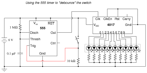
Please note that since we are using the 555 once again to provide a clock signal to the 4017, we must re-connect pin #3 of the 555 chip to pin #14 of the 4017 chip! Also, if you have altered the values of the resistor or capacitor in the 555 timer circuit, you should return to the original 1 MΩ and 0.1 µF components.
Actuate the switch again and note the counting behavior of the 4017. There should be no more “skipped” counts as there were before because the 555 timer outputs a single, crisp pulse for every on-to-off actuation (notice the inversion of operation here!) of the switch. It is important that the timing of the 555 circuit be appropriate: the time to charge the capacitor should be longer than the “settling” period of the switch (the time required for the contacts to stop bouncing), but not so long that the timer would “miss” a rapid sequence of switch actuation, if they were to occur.