
8.4: 555 Monostable Multivibrator
- Page ID
- 1288

\( \newcommand{\vecs}[1]{\overset { \scriptstyle \rightharpoonup} {\mathbf{#1}} } \)
\( \newcommand{\vecd}[1]{\overset{-\!-\!\rightharpoonup}{\vphantom{a}\smash {#1}}} \)
\( \newcommand{\dsum}{\displaystyle\sum\limits} \)
\( \newcommand{\dint}{\displaystyle\int\limits} \)
\( \newcommand{\dlim}{\displaystyle\lim\limits} \)
\( \newcommand{\id}{\mathrm{id}}\) \( \newcommand{\Span}{\mathrm{span}}\)
( \newcommand{\kernel}{\mathrm{null}\,}\) \( \newcommand{\range}{\mathrm{range}\,}\)
\( \newcommand{\RealPart}{\mathrm{Re}}\) \( \newcommand{\ImaginaryPart}{\mathrm{Im}}\)
\( \newcommand{\Argument}{\mathrm{Arg}}\) \( \newcommand{\norm}[1]{\| #1 \|}\)
\( \newcommand{\inner}[2]{\langle #1, #2 \rangle}\)
\( \newcommand{\Span}{\mathrm{span}}\)
\( \newcommand{\id}{\mathrm{id}}\)
\( \newcommand{\Span}{\mathrm{span}}\)
\( \newcommand{\kernel}{\mathrm{null}\,}\)
\( \newcommand{\range}{\mathrm{range}\,}\)
\( \newcommand{\RealPart}{\mathrm{Re}}\)
\( \newcommand{\ImaginaryPart}{\mathrm{Im}}\)
\( \newcommand{\Argument}{\mathrm{Arg}}\)
\( \newcommand{\norm}[1]{\| #1 \|}\)
\( \newcommand{\inner}[2]{\langle #1, #2 \rangle}\)
\( \newcommand{\Span}{\mathrm{span}}\) \( \newcommand{\AA}{\unicode[.8,0]{x212B}}\)
\( \newcommand{\vectorA}[1]{\vec{#1}} % arrow\)
\( \newcommand{\vectorAt}[1]{\vec{\text{#1}}} % arrow\)
\( \newcommand{\vectorB}[1]{\overset { \scriptstyle \rightharpoonup} {\mathbf{#1}} } \)
\( \newcommand{\vectorC}[1]{\textbf{#1}} \)
\( \newcommand{\vectorD}[1]{\overrightarrow{#1}} \)
\( \newcommand{\vectorDt}[1]{\overrightarrow{\text{#1}}} \)
\( \newcommand{\vectE}[1]{\overset{-\!-\!\rightharpoonup}{\vphantom{a}\smash{\mathbf {#1}}}} \)
\( \newcommand{\vecs}[1]{\overset { \scriptstyle \rightharpoonup} {\mathbf{#1}} } \)
\(\newcommand{\longvect}{\overrightarrow}\)
\( \newcommand{\vecd}[1]{\overset{-\!-\!\rightharpoonup}{\vphantom{a}\smash {#1}}} \)
\(\newcommand{\avec}{\mathbf a}\) \(\newcommand{\bvec}{\mathbf b}\) \(\newcommand{\cvec}{\mathbf c}\) \(\newcommand{\dvec}{\mathbf d}\) \(\newcommand{\dtil}{\widetilde{\mathbf d}}\) \(\newcommand{\evec}{\mathbf e}\) \(\newcommand{\fvec}{\mathbf f}\) \(\newcommand{\nvec}{\mathbf n}\) \(\newcommand{\pvec}{\mathbf p}\) \(\newcommand{\qvec}{\mathbf q}\) \(\newcommand{\svec}{\mathbf s}\) \(\newcommand{\tvec}{\mathbf t}\) \(\newcommand{\uvec}{\mathbf u}\) \(\newcommand{\vvec}{\mathbf v}\) \(\newcommand{\wvec}{\mathbf w}\) \(\newcommand{\xvec}{\mathbf x}\) \(\newcommand{\yvec}{\mathbf y}\) \(\newcommand{\zvec}{\mathbf z}\) \(\newcommand{\rvec}{\mathbf r}\) \(\newcommand{\mvec}{\mathbf m}\) \(\newcommand{\zerovec}{\mathbf 0}\) \(\newcommand{\onevec}{\mathbf 1}\) \(\newcommand{\real}{\mathbb R}\) \(\newcommand{\twovec}[2]{\left[\begin{array}{r}#1 \\ #2 \end{array}\right]}\) \(\newcommand{\ctwovec}[2]{\left[\begin{array}{c}#1 \\ #2 \end{array}\right]}\) \(\newcommand{\threevec}[3]{\left[\begin{array}{r}#1 \\ #2 \\ #3 \end{array}\right]}\) \(\newcommand{\cthreevec}[3]{\left[\begin{array}{c}#1 \\ #2 \\ #3 \end{array}\right]}\) \(\newcommand{\fourvec}[4]{\left[\begin{array}{r}#1 \\ #2 \\ #3 \\ #4 \end{array}\right]}\) \(\newcommand{\cfourvec}[4]{\left[\begin{array}{c}#1 \\ #2 \\ #3 \\ #4 \end{array}\right]}\) \(\newcommand{\fivevec}[5]{\left[\begin{array}{r}#1 \\ #2 \\ #3 \\ #4 \\ #5 \\ \end{array}\right]}\) \(\newcommand{\cfivevec}[5]{\left[\begin{array}{c}#1 \\ #2 \\ #3 \\ #4 \\ #5 \\ \end{array}\right]}\) \(\newcommand{\mattwo}[4]{\left[\begin{array}{rr}#1 \amp #2 \\ #3 \amp #4 \\ \end{array}\right]}\) \(\newcommand{\laspan}[1]{\text{Span}\{#1\}}\) \(\newcommand{\bcal}{\cal B}\) \(\newcommand{\ccal}{\cal C}\) \(\newcommand{\scal}{\cal S}\) \(\newcommand{\wcal}{\cal W}\) \(\newcommand{\ecal}{\cal E}\) \(\newcommand{\coords}[2]{\left\{#1\right\}_{#2}}\) \(\newcommand{\gray}[1]{\color{gray}{#1}}\) \(\newcommand{\lgray}[1]{\color{lightgray}{#1}}\) \(\newcommand{\rank}{\operatorname{rank}}\) \(\newcommand{\row}{\text{Row}}\) \(\newcommand{\col}{\text{Col}}\) \(\renewcommand{\row}{\text{Row}}\) \(\newcommand{\nul}{\text{Nul}}\) \(\newcommand{\var}{\text{Var}}\) \(\newcommand{\corr}{\text{corr}}\) \(\newcommand{\len}[1]{\left|#1\right|}\) \(\newcommand{\bbar}{\overline{\bvec}}\) \(\newcommand{\bhat}{\widehat{\bvec}}\) \(\newcommand{\bperp}{\bvec^\perp}\) \(\newcommand{\xhat}{\widehat{\xvec}}\) \(\newcommand{\vhat}{\widehat{\vvec}}\) \(\newcommand{\uhat}{\widehat{\uvec}}\) \(\newcommand{\what}{\widehat{\wvec}}\) \(\newcommand{\Sighat}{\widehat{\Sigma}}\) \(\newcommand{\lt}{<}\) \(\newcommand{\gt}{>}\) \(\newcommand{\amp}{&}\) \(\definecolor{fillinmathshade}{gray}{0.9}\)PARTS AND MATERIALS
- One 9V Battery
- Battery Clip (Radio Shack catalog # 270-325)
- Mini Hook Clips (soldered to Battery Clip, Radio Shack catalog # 270-372)
- A Watch with a second hand/display or a Stop Watch
- A wire, 11/2” to 2” (3.8 mm to 5 mm) long, folded in half (shown as red wire in illustration)
- U1 - 555 timer IC (Radio Shack catalog # 276-1723)
- D1 - Red light-emitting diode (Radio Shack catalog # 276-041 or equivalent)
- D2 - Green light-emitting diode (Radio Shack catalog # 276-022 or equivalent)
- R1,R2 - 1 KΩ 1/4W Resistors
- Rt - 27 KΩ 1/4W Resistor
- Rt - 270 KΩ 1/4W Resistor
- C1,C2 - 0.1 µF Capacitor (Radio Shack catalog 272-1069 or equivalent)
- Ct - 10 µF Capacitor (Radio Shack catalog 272-1025 or equivalent)
- Ct - 100 µF Capacitor (Radio Shack catalog 272-1028 or equivalent)
CROSS-REFERENCES
Lessons In Electric Circuits, Volume 1, chapter 13: “Electric fields and capacitance”
Lessons In Electric Circuits, Volume 1, chapter 13: “Capacitors and calculus”
Lessons In Electric Circuits, Volume 1, chapter 16: “Voltage and current calculations”
Lessons In Electric Circuits, Volume 1, chapter 16: “Solving for unknown time”
Lessons In Electric Circuits, Volume 4, chapter 10: “Monostable multivibrators”
LEARNING OBJECTIVES
- Learn how a Monostable Multivibrator works
- Learn a practical application for a RC time constant
- How to use the 555 timer as a Monostable Multivibrator
SCHEMATIC DIAGRAM
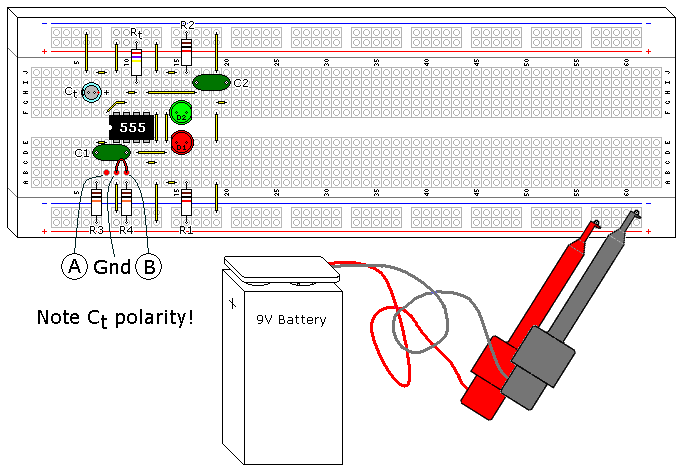
ILLUSTRATION
INSTRUCTIONS
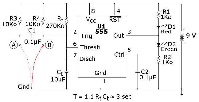
This is one of the most basic 555 circuits. This circuit is part of this chips datasheet, complete with the math needed to design to specification, and is one of the reasons a 555 is referred to as a timer. The green LED shown on the illustration lights when the 555 output is high (i.e., switched to Vcc), and the red LED lights when the 555 output is low (switched to ground).
This particular monostable multivibrator (also known as a monostable or timer) is not a retriggerable type. This means once triggered it will ignore further inputs during a timing cycle, with one exception, which will be discussed in the next paragraph. The timer starts when the input goes low or switched to the ground level, and the output goes high. You can prove this by connecting the red wire shown on the illustration between ground and point B, disconnecting it, and reconnecting it.
It is an illegal condition for the input to stay low for this design past timeout. For this reason, R3 and C1 were added to create a signal conditioner, which will allow edge only triggering and prevent the illegal input. You can prove this by connecting the red wire between ground and point A. The timer will start when the wire is inserted into the protoboard between these two points, and ignore further contacts. If you force the timer input to stay low past timeout the output will stay high, even though the timer has finished. As soon as this ground is removed the timer will go low.
Rt and Ct were selected for 3 seconds timing duration. You can verify this with a watch, 3 seconds is long enough that we slow humans can actually measure it. Try swapping Rt and Ct with the 27 KO resistor and the 100 µF capacitors. Since the answer to the formula is the same there should be no difference in how it operates. Next try swapping Rt with the 270 KO resistor, since the RC time constant is now 10 times greater you should get close to 30 seconds. The resistor and capacitor are probably 5% and 20% tolerance respectively, so the calculated times you measure can vary as much as 25%, though it will usually be much closer.
Another nice feature of the 555 is its immunity from the power supply voltage. If you were to swap the 9V battery with a 6V or 12 battery you should get identical results, though the LED light intensity will change.
C2 isn’t actually necessary. The 555 IC has this option in case the timer is being used in an environment where the power supply line is noisy. You can remove it and not notice a difference. The 555 itself is a source of noise since there is a very brief period of time that the transistors on both sides of the output are both conducting, creating a power surge (measured in nanoseconds) from the power supply.
THEORY OF OPERATION
Looking at the functional schematic shown (Figure below), you can see that pin 7 is a transistor going to ground.
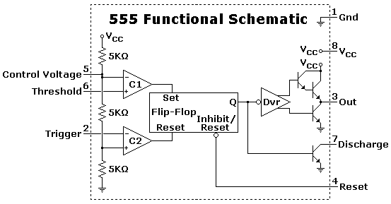
This transistor is simply a switch that normally conducts until pin 2 (which is connected through the comparator C1, which feeds the internal flip-flop) is brought low, allowing the capacitor Ct to start charging. Pin 7 stays off until the voltage on Ct charges to 2/3 of the power supply voltage, where the timer times out and pin 7 transistor turns on again, its normal state in this circuit.
The following (Figure below) will show the sequence of switching, with red being the higher voltages and green being ground (0 volts), with the spectrum in between since this is fundamentally an analog circuit.
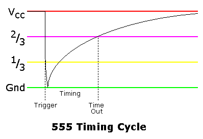
This graph shows the charge curve across the Ct.
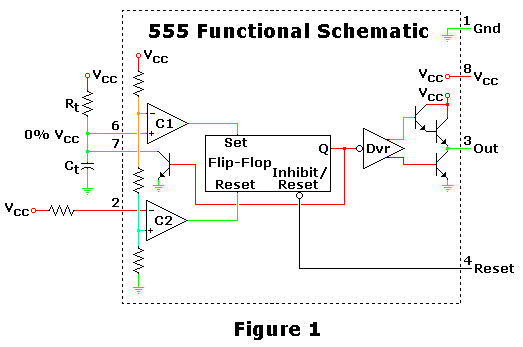
Figure 1 is the starting and ending point for this circuit, where it is waiting for a trigger to start a timing cycle. At this point the pin 7 transistor is on, keeping the capacitor Ct discharged.
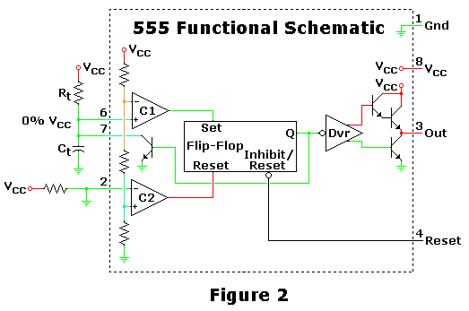
Figure 2 shows what happens when the 555 receives a trigger, starting the sequence. Ct hasn’t had time to accumulate voltage, but the charging has started.
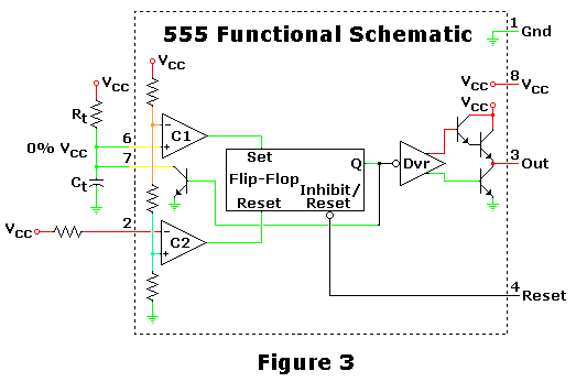
Figure 3 shows the capacitor charging, during this time the circuit is in a stable configuration and the output is high.
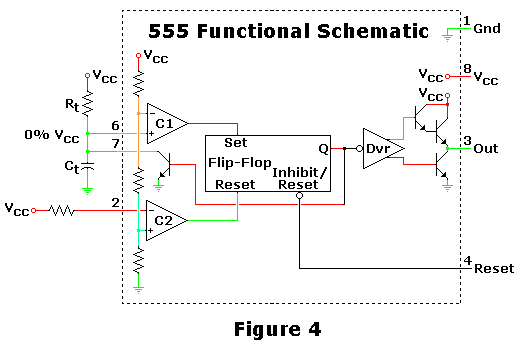
Figure 4 shows the circuit in the middle of switching off when it hits timeout. The capacitor has charged to 67%, the upper limit of the 555 circuit, causing its internal flip-flop to switch states. As shown, the transistor hasn’t switched yet, which will discharge Ct when it does.
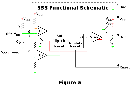
Figure 5 shows the circuit after it has settled down, which is basically the same as shown in Figure 1.