
8.5: CMOS 555 Long Duration Minimum Parts Red LED Flasher
- Page ID
- 1289

\( \newcommand{\vecs}[1]{\overset { \scriptstyle \rightharpoonup} {\mathbf{#1}} } \)
\( \newcommand{\vecd}[1]{\overset{-\!-\!\rightharpoonup}{\vphantom{a}\smash {#1}}} \)
\( \newcommand{\id}{\mathrm{id}}\) \( \newcommand{\Span}{\mathrm{span}}\)
( \newcommand{\kernel}{\mathrm{null}\,}\) \( \newcommand{\range}{\mathrm{range}\,}\)
\( \newcommand{\RealPart}{\mathrm{Re}}\) \( \newcommand{\ImaginaryPart}{\mathrm{Im}}\)
\( \newcommand{\Argument}{\mathrm{Arg}}\) \( \newcommand{\norm}[1]{\| #1 \|}\)
\( \newcommand{\inner}[2]{\langle #1, #2 \rangle}\)
\( \newcommand{\Span}{\mathrm{span}}\)
\( \newcommand{\id}{\mathrm{id}}\)
\( \newcommand{\Span}{\mathrm{span}}\)
\( \newcommand{\kernel}{\mathrm{null}\,}\)
\( \newcommand{\range}{\mathrm{range}\,}\)
\( \newcommand{\RealPart}{\mathrm{Re}}\)
\( \newcommand{\ImaginaryPart}{\mathrm{Im}}\)
\( \newcommand{\Argument}{\mathrm{Arg}}\)
\( \newcommand{\norm}[1]{\| #1 \|}\)
\( \newcommand{\inner}[2]{\langle #1, #2 \rangle}\)
\( \newcommand{\Span}{\mathrm{span}}\) \( \newcommand{\AA}{\unicode[.8,0]{x212B}}\)
\( \newcommand{\vectorA}[1]{\vec{#1}} % arrow\)
\( \newcommand{\vectorAt}[1]{\vec{\text{#1}}} % arrow\)
\( \newcommand{\vectorB}[1]{\overset { \scriptstyle \rightharpoonup} {\mathbf{#1}} } \)
\( \newcommand{\vectorC}[1]{\textbf{#1}} \)
\( \newcommand{\vectorD}[1]{\overrightarrow{#1}} \)
\( \newcommand{\vectorDt}[1]{\overrightarrow{\text{#1}}} \)
\( \newcommand{\vectE}[1]{\overset{-\!-\!\rightharpoonup}{\vphantom{a}\smash{\mathbf {#1}}}} \)
\( \newcommand{\vecs}[1]{\overset { \scriptstyle \rightharpoonup} {\mathbf{#1}} } \)
\( \newcommand{\vecd}[1]{\overset{-\!-\!\rightharpoonup}{\vphantom{a}\smash {#1}}} \)
\(\newcommand{\avec}{\mathbf a}\) \(\newcommand{\bvec}{\mathbf b}\) \(\newcommand{\cvec}{\mathbf c}\) \(\newcommand{\dvec}{\mathbf d}\) \(\newcommand{\dtil}{\widetilde{\mathbf d}}\) \(\newcommand{\evec}{\mathbf e}\) \(\newcommand{\fvec}{\mathbf f}\) \(\newcommand{\nvec}{\mathbf n}\) \(\newcommand{\pvec}{\mathbf p}\) \(\newcommand{\qvec}{\mathbf q}\) \(\newcommand{\svec}{\mathbf s}\) \(\newcommand{\tvec}{\mathbf t}\) \(\newcommand{\uvec}{\mathbf u}\) \(\newcommand{\vvec}{\mathbf v}\) \(\newcommand{\wvec}{\mathbf w}\) \(\newcommand{\xvec}{\mathbf x}\) \(\newcommand{\yvec}{\mathbf y}\) \(\newcommand{\zvec}{\mathbf z}\) \(\newcommand{\rvec}{\mathbf r}\) \(\newcommand{\mvec}{\mathbf m}\) \(\newcommand{\zerovec}{\mathbf 0}\) \(\newcommand{\onevec}{\mathbf 1}\) \(\newcommand{\real}{\mathbb R}\) \(\newcommand{\twovec}[2]{\left[\begin{array}{r}#1 \\ #2 \end{array}\right]}\) \(\newcommand{\ctwovec}[2]{\left[\begin{array}{c}#1 \\ #2 \end{array}\right]}\) \(\newcommand{\threevec}[3]{\left[\begin{array}{r}#1 \\ #2 \\ #3 \end{array}\right]}\) \(\newcommand{\cthreevec}[3]{\left[\begin{array}{c}#1 \\ #2 \\ #3 \end{array}\right]}\) \(\newcommand{\fourvec}[4]{\left[\begin{array}{r}#1 \\ #2 \\ #3 \\ #4 \end{array}\right]}\) \(\newcommand{\cfourvec}[4]{\left[\begin{array}{c}#1 \\ #2 \\ #3 \\ #4 \end{array}\right]}\) \(\newcommand{\fivevec}[5]{\left[\begin{array}{r}#1 \\ #2 \\ #3 \\ #4 \\ #5 \\ \end{array}\right]}\) \(\newcommand{\cfivevec}[5]{\left[\begin{array}{c}#1 \\ #2 \\ #3 \\ #4 \\ #5 \\ \end{array}\right]}\) \(\newcommand{\mattwo}[4]{\left[\begin{array}{rr}#1 \amp #2 \\ #3 \amp #4 \\ \end{array}\right]}\) \(\newcommand{\laspan}[1]{\text{Span}\{#1\}}\) \(\newcommand{\bcal}{\cal B}\) \(\newcommand{\ccal}{\cal C}\) \(\newcommand{\scal}{\cal S}\) \(\newcommand{\wcal}{\cal W}\) \(\newcommand{\ecal}{\cal E}\) \(\newcommand{\coords}[2]{\left\{#1\right\}_{#2}}\) \(\newcommand{\gray}[1]{\color{gray}{#1}}\) \(\newcommand{\lgray}[1]{\color{lightgray}{#1}}\) \(\newcommand{\rank}{\operatorname{rank}}\) \(\newcommand{\row}{\text{Row}}\) \(\newcommand{\col}{\text{Col}}\) \(\renewcommand{\row}{\text{Row}}\) \(\newcommand{\nul}{\text{Nul}}\) \(\newcommand{\var}{\text{Var}}\) \(\newcommand{\corr}{\text{corr}}\) \(\newcommand{\len}[1]{\left|#1\right|}\) \(\newcommand{\bbar}{\overline{\bvec}}\) \(\newcommand{\bhat}{\widehat{\bvec}}\) \(\newcommand{\bperp}{\bvec^\perp}\) \(\newcommand{\xhat}{\widehat{\xvec}}\) \(\newcommand{\vhat}{\widehat{\vvec}}\) \(\newcommand{\uhat}{\widehat{\uvec}}\) \(\newcommand{\what}{\widehat{\wvec}}\) \(\newcommand{\Sighat}{\widehat{\Sigma}}\) \(\newcommand{\lt}{<}\) \(\newcommand{\gt}{>}\) \(\newcommand{\amp}{&}\) \(\definecolor{fillinmathshade}{gray}{0.9}\)PARTS AND MATERIALS
- Two AAA Batteries
- Battery Clip (Radio Shack catalog # 270-398B)
- One DVM or VOM
- U1 - T One CMOS TLC555 timer IC (Radio Shack catalog # 276-1718 or equivalent)
- D1 - Red light-emitting diode (Radio Shack catalog # 276-041 or equivalent)
- R1 - 1.5 MΩ 1/4W 5% Resistor
- R2 - 47 KΩ 1/4W 5% Resistor
- C1 - 1 µF Tantalum Capacitor (Radio Shack catalog 272-1025 or equivalent)
- C2 - 100 µF Electrolytic Capacitor (Radio Shack catalog 272-1028 or equivalent)
CROSS-REFERENCES
Lessons In Electric Circuits, Volume 1, chapter 16: “Voltage and current calculations”
Lessons In Electric Circuits, Volume 1, chapter 16: “Solving for unknown time”
Lessons In Electric Circuits, Volume 3, chapter 9 : “ElectroStatic Discharge”
Lessons In Electric Circuits, Volume 4, chapter 10: “Multivibrators”
LEARNING OBJECTIVES
- Learn a practical application for a RC time constant
- Learn one of several 555 timer Astable Multivibrator Configurations
- Working knowledge of duty cycle
- Learn how to handle ESD sensitive parts
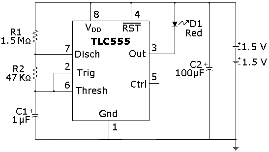
SCHEMATIC DIAGRAM
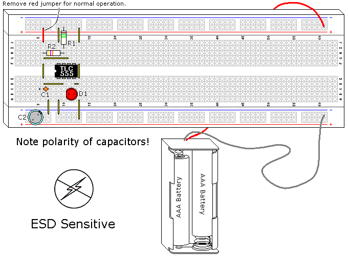
ILLUSTRATION
INSTRUCTIONS
NOTE! This project uses a static sensitive part, the CMOS 555. If you do not use protection as described in Volume 3, Chapter 9, ElectroStatic Discharge, you run the risk of destroying it.
The 555 is not a power hog, but it is a child of the 1970’s, created in 1971. It will suck a battery dry in days, if not hours. Fortunately, the design has been reinvented using CMOS technology. The new implementation isn’t perfect, as it lacks the fantastic current drive of the original, but for a CMOS device the output current is still very good. The main advantages include wider supply voltage range (power supply specifications are 2V to 18V, and it will work using an 11/2V battery) and low power. This project uses the TLC555, a Texas Instruments design. There are other CMOS 555’s out there, very similar but with some differences. These chips are designed to be drop-in replacements and do very well as long as the output is not substantially loaded.
This design turns a deficit into an advantage as the current drive only gets worse at lower power supply voltages, its specifications are not more than 3ma for 2VDC. This design tries to make the batteries last as absolutely long as possible using several different approaches. The CMOS IC is extremely low current, and sends the LED a pulse of 30ms (which is a very short time but within persistence of human vision) as well as using a slow flash rate (1 second) using really large resistors to minimize current. With a duty cycle of 3%, this circuit spends most of its time off, and (assuming 20ma for the LED) the average current is 0.6ma. The big problem is using the built-in current limitation of this IC, as is it is not rated for a specific current, and the LED current can vary a lot between different CMOS ICs.
It is possible to run into problems with electrolytic capacitors when dealing with very low currents (2µa in this case) in that the leakage can be excessive, a borderline failure condition. If your experiment seems to do this it might be fixed by charging across the battery, then discharging the capacitor C1 across any conductor several times.
When you complete this circuit the LED should start flashing and would continue to do so for several months. If you use larger batteries, such as D cells, this duration will increase dramatically.
To measure the current draw feeding the LED, connect C1+ to Vcc with a jumper (shown in red on the Illustration), which will turn the TLC555 on. Measure the amperage flowing from the battery to the circuit. The target current is 20ma, I measured 9ma to 24ma using different CMOS 555s. This isn’t critical, though it will affect the battery life.
THEORY OF OPERATION
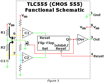
An observant reader will note that this is fundamentally the same circuit that was used in the 555 AUDIO OSCILLATOR experiment. Many designs use the same basic designs and concepts several different ways, this is such a case. A conventional 555 IC would work in this design if the power supply weren’t so low and a LED current limiting resistor is used. Other than the type of transistors used the block diagram shown in Figure 1 is basically the same as a conventional 555.
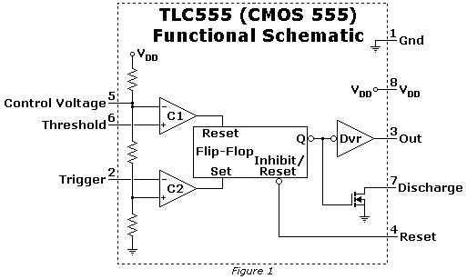
This particular oscillator depends on the pin 7 transistor, much like the 555 Monostable Multivibrator shown in an earlier experiment. The startup condition is with the capacitor discharged, the output high, and pin 7 transistor off. The capacitor starts charging as shown in Figure 2.
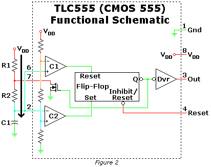
When the voltage across pins 2 and 6 reaches 2/3 of the power supply the flip flop is reset via internal comparator C1, which turns on the Pin 7 transistor, and starts the capacitor C1 discharging through R2 as shown in Figure 3. The current shown through R1 is incidental, and not important other than it drains the battery. This is why this resistor value is so large.
When the voltage across pins 2 and 6 reaches 1/3 of the power supply the flip-flop is set via internal comparator C2, when turns off the pin 7 transistor, allowing the capacitor to start charging again through R1 and R2, as shown in Figure 2. This cycle repeats.
Capacitor C2 extends the life of the batteries, since it will store the voltage during the 97% of time the circuit is off, and provide the current during the 3% it is on. This simple addition will take the batteries beyond their useful life by a large margin.
In running this experiment there was a feedback mechanism I hadn’t anticipated. The output current of the TLC555 is not proportional, as the power supply voltage goes down the output current reduces a lot more. My flasher lasted for 6 months before I terminated the experiment. It was still flashing, it was just very dim.