3.2: Electricity and Magnetism
- Page ID
- 3273
\( \newcommand{\vecs}[1]{\overset { \scriptstyle \rightharpoonup} {\mathbf{#1}} } \)
\( \newcommand{\vecd}[1]{\overset{-\!-\!\rightharpoonup}{\vphantom{a}\smash {#1}}} \)
\( \newcommand{\id}{\mathrm{id}}\) \( \newcommand{\Span}{\mathrm{span}}\)
( \newcommand{\kernel}{\mathrm{null}\,}\) \( \newcommand{\range}{\mathrm{range}\,}\)
\( \newcommand{\RealPart}{\mathrm{Re}}\) \( \newcommand{\ImaginaryPart}{\mathrm{Im}}\)
\( \newcommand{\Argument}{\mathrm{Arg}}\) \( \newcommand{\norm}[1]{\| #1 \|}\)
\( \newcommand{\inner}[2]{\langle #1, #2 \rangle}\)
\( \newcommand{\Span}{\mathrm{span}}\)
\( \newcommand{\id}{\mathrm{id}}\)
\( \newcommand{\Span}{\mathrm{span}}\)
\( \newcommand{\kernel}{\mathrm{null}\,}\)
\( \newcommand{\range}{\mathrm{range}\,}\)
\( \newcommand{\RealPart}{\mathrm{Re}}\)
\( \newcommand{\ImaginaryPart}{\mathrm{Im}}\)
\( \newcommand{\Argument}{\mathrm{Arg}}\)
\( \newcommand{\norm}[1]{\| #1 \|}\)
\( \newcommand{\inner}[2]{\langle #1, #2 \rangle}\)
\( \newcommand{\Span}{\mathrm{span}}\) \( \newcommand{\AA}{\unicode[.8,0]{x212B}}\)
\( \newcommand{\vectorA}[1]{\vec{#1}} % arrow\)
\( \newcommand{\vectorAt}[1]{\vec{\text{#1}}} % arrow\)
\( \newcommand{\vectorB}[1]{\overset { \scriptstyle \rightharpoonup} {\mathbf{#1}} } \)
\( \newcommand{\vectorC}[1]{\textbf{#1}} \)
\( \newcommand{\vectorD}[1]{\overrightarrow{#1}} \)
\( \newcommand{\vectorDt}[1]{\overrightarrow{\text{#1}}} \)
\( \newcommand{\vectE}[1]{\overset{-\!-\!\rightharpoonup}{\vphantom{a}\smash{\mathbf {#1}}}} \)
\( \newcommand{\vecs}[1]{\overset { \scriptstyle \rightharpoonup} {\mathbf{#1}} } \)
\( \newcommand{\vecd}[1]{\overset{-\!-\!\rightharpoonup}{\vphantom{a}\smash {#1}}} \)
\(\newcommand{\avec}{\mathbf a}\) \(\newcommand{\bvec}{\mathbf b}\) \(\newcommand{\cvec}{\mathbf c}\) \(\newcommand{\dvec}{\mathbf d}\) \(\newcommand{\dtil}{\widetilde{\mathbf d}}\) \(\newcommand{\evec}{\mathbf e}\) \(\newcommand{\fvec}{\mathbf f}\) \(\newcommand{\nvec}{\mathbf n}\) \(\newcommand{\pvec}{\mathbf p}\) \(\newcommand{\qvec}{\mathbf q}\) \(\newcommand{\svec}{\mathbf s}\) \(\newcommand{\tvec}{\mathbf t}\) \(\newcommand{\uvec}{\mathbf u}\) \(\newcommand{\vvec}{\mathbf v}\) \(\newcommand{\wvec}{\mathbf w}\) \(\newcommand{\xvec}{\mathbf x}\) \(\newcommand{\yvec}{\mathbf y}\) \(\newcommand{\zvec}{\mathbf z}\) \(\newcommand{\rvec}{\mathbf r}\) \(\newcommand{\mvec}{\mathbf m}\) \(\newcommand{\zerovec}{\mathbf 0}\) \(\newcommand{\onevec}{\mathbf 1}\) \(\newcommand{\real}{\mathbb R}\) \(\newcommand{\twovec}[2]{\left[\begin{array}{r}#1 \\ #2 \end{array}\right]}\) \(\newcommand{\ctwovec}[2]{\left[\begin{array}{c}#1 \\ #2 \end{array}\right]}\) \(\newcommand{\threevec}[3]{\left[\begin{array}{r}#1 \\ #2 \\ #3 \end{array}\right]}\) \(\newcommand{\cthreevec}[3]{\left[\begin{array}{c}#1 \\ #2 \\ #3 \end{array}\right]}\) \(\newcommand{\fourvec}[4]{\left[\begin{array}{r}#1 \\ #2 \\ #3 \\ #4 \end{array}\right]}\) \(\newcommand{\cfourvec}[4]{\left[\begin{array}{c}#1 \\ #2 \\ #3 \\ #4 \end{array}\right]}\) \(\newcommand{\fivevec}[5]{\left[\begin{array}{r}#1 \\ #2 \\ #3 \\ #4 \\ #5 \\ \end{array}\right]}\) \(\newcommand{\cfivevec}[5]{\left[\begin{array}{c}#1 \\ #2 \\ #3 \\ #4 \\ #5 \\ \end{array}\right]}\) \(\newcommand{\mattwo}[4]{\left[\begin{array}{rr}#1 \amp #2 \\ #3 \amp #4 \\ \end{array}\right]}\) \(\newcommand{\laspan}[1]{\text{Span}\{#1\}}\) \(\newcommand{\bcal}{\cal B}\) \(\newcommand{\ccal}{\cal C}\) \(\newcommand{\scal}{\cal S}\) \(\newcommand{\wcal}{\cal W}\) \(\newcommand{\ecal}{\cal E}\) \(\newcommand{\coords}[2]{\left\{#1\right\}_{#2}}\) \(\newcommand{\gray}[1]{\color{gray}{#1}}\) \(\newcommand{\lgray}[1]{\color{lightgray}{#1}}\) \(\newcommand{\rank}{\operatorname{rank}}\) \(\newcommand{\row}{\text{Row}}\) \(\newcommand{\col}{\text{Col}}\) \(\renewcommand{\row}{\text{Row}}\) \(\newcommand{\nul}{\text{Nul}}\) \(\newcommand{\var}{\text{Var}}\) \(\newcommand{\corr}{\text{corr}}\) \(\newcommand{\len}[1]{\left|#1\right|}\) \(\newcommand{\bbar}{\overline{\bvec}}\) \(\newcommand{\bhat}{\widehat{\bvec}}\) \(\newcommand{\bperp}{\bvec^\perp}\) \(\newcommand{\xhat}{\widehat{\xvec}}\) \(\newcommand{\vhat}{\widehat{\vvec}}\) \(\newcommand{\uhat}{\widehat{\uvec}}\) \(\newcommand{\what}{\widehat{\wvec}}\) \(\newcommand{\Sighat}{\widehat{\Sigma}}\) \(\newcommand{\lt}{<}\) \(\newcommand{\gt}{>}\) \(\newcommand{\amp}{&}\) \(\definecolor{fillinmathshade}{gray}{0.9}\)Electricity and magnetism
There is a direct relationship between electricity and magnetism. If there is current flow in a conductor there will be lines of force created around the conductor. If you could look at the magnetic field formed around a current-carrying conductor, it would look like Figure \(\PageIndex{1}\).
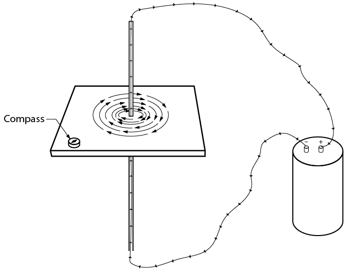
Note that the lines of force circle the conductor in rings and have direction. The direction of the lines of force depends on the direction of electron flow. If you know the direction of electron flow, you can determine the direction of the lines of force by using your left hand.
The “left-hand rule” says that if you hold the conductor in your left hand with your thumb pointing in the direction of the electron current flow, your fingers will curl in the direction of the lines of force. You will sometimes find this referenced as the “right-hand rule” from those using convention flow notation.
Interaction of fields
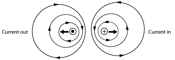
Magnetic fields around a current-carrying conductor act in the same way as the fields around a permanent magnet. In Figure \(\PageIndex{2}\), two conductors have been moved close together. The current is going in opposite directions, as indicated by the symbol in the end of the conductor. An X indicates electron flow in; a dot indicates electron flow out. The magnetic lines of force try to push the two conductors apart because they are in opposite directions. The arrows indicate the direction of the magnetic force.
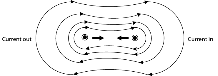
If one of the conductors has the current reversed, then the magnetic lines of force travel in the same directions. When this occurs the lines of force try to contract and pull tight, just as they did with a permanent magnet. The resulting force will try to pull the two conductors together (Figure \(\PageIndex{3}\)).
Conductors in loops
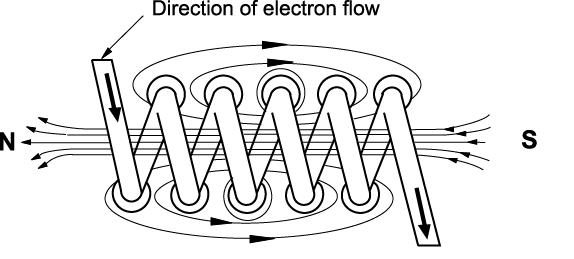
If a conductor carrying a current is formed into a loop, the magnetic field will be arranged differently. It will form looped lines of force with a north pole on one side of the loop and a south pole on the other. The magnetic flux lines add to each other and produce a much denser magnetic field in the center of the coil (Figure \(\PageIndex{4}\)).
Electromagnets
If a piece of soft iron is placed in the coil and a current is passed through the coil in one direction, the magnetic field of the coil causes the domains to align in the iron. This causes poles to form in the iron and creates an electromagnet, as shown in \(\PageIndex{5}\).
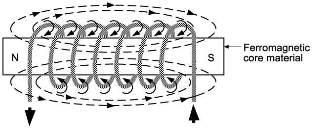
The strength of the electromagnet varies with the number of loops formed, the strength of the electric current, and the type of core in the winding. Because the iron core has a low magnetic retention, the magnetic field collapses when the current stops flowing. The iron core is no longer magnetized and will release whatever it was being used to hold or pull inward.
Electric motors and generators
Electromagnets are probably most commonly used in motors and generators. We have seen that magnetism can be caused by electricity. Electric motors use the force of electromagnets to produce rotation. On the other hand, electricity can be produced by magnetism. When a conductor is moved through a magnetic field or a magnet is moved past a conductor, the movement will induce a voltage in the conductor. Most electricity is generated in this way.
To generate a voltage, three elements must be combined (Figure \(\PageIndex{6}\):
- a conductor
- a magnetic field
- movement by either the conductor or the magnetic field
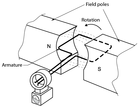
The amount of voltage produced will depend on the strength of the magnetic field and the speed at which the conductor or the field moves. A conductor that moves through a magnetic field quickly will generate a higher voltage than one that moves more slowly.
A conductor that moves through a strong magnetic field will generate a higher voltage than one moved through a weak magnetic field.
Alternating current
Electric current that flows in one direction for a split second then changes direction in another split second is called alternating current (AC). In an alternating voltage, the polarity reverses direction periodically. The spinning mechanical motion of an electric generator produces AC voltage and current.
AC waveform and hertz
Hertz is the unit used to describe the frequency of AC direction change. Figure \(\PageIndex{7}\) is a graphic illustration using a curved line with arrows to indicate a change of direction in AC electron flow. Starting at point A, the current flows in one direction, and then at 120 volts it changes direction, drops to 0 volts, and continues to 120 volts, where it changes direction again back to point B at 0 volts.
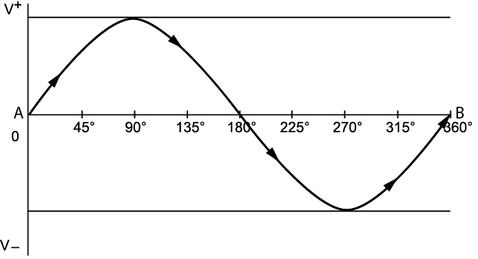
If it takes one second to complete the cycle from A to B, we would say the frequency is 1 hertz. Household utility AC current is supplied to the customer at 60 hertz, meaning 60 cycles per second.
Single-phase power supply
Single-phase electric power refers to the distribution of alternating current electric power using a system in which all the voltages of the supply vary in unison. Single-phase distribution is used when loads are mostly lighting and heating, and with a few large electric motors. Single-phase power typically comprises one voltage that is carried between two separate conductors. The two hot lines are called Line 1 and Line 2. In some systems, a grounded neutral, often labeled N, is provided that reduces the referenced voltage in half. These systems are typically found in residential and small commercial applications.
Three-phase AC power supply
Three-phase electrical power refers to a type of electrical power distribution in which three or more energized electrical conductors are carrying alternating currents. Examples of three-phase power systems are industrial applications and power transmission. Three-phase power supplies are used to power large motors and other heavy loads. A three-phase system is generally more economical than equivalent single-phase or two-phase (an uncommon power supply) systems at the same voltage.
Three-phase power comprises three independent voltages that are carried on three separate conductors. The three hot lines are called Line 1, Line 2, and Line 3. Three-phase power is typically found in commercial and industrial buildings.
 Now complete the Learning Task Self-Test.


