7.4: Three-wire Power Supply System
- Page ID
- 3306
\( \newcommand{\vecs}[1]{\overset { \scriptstyle \rightharpoonup} {\mathbf{#1}} } \)
\( \newcommand{\vecd}[1]{\overset{-\!-\!\rightharpoonup}{\vphantom{a}\smash {#1}}} \)
\( \newcommand{\id}{\mathrm{id}}\) \( \newcommand{\Span}{\mathrm{span}}\)
( \newcommand{\kernel}{\mathrm{null}\,}\) \( \newcommand{\range}{\mathrm{range}\,}\)
\( \newcommand{\RealPart}{\mathrm{Re}}\) \( \newcommand{\ImaginaryPart}{\mathrm{Im}}\)
\( \newcommand{\Argument}{\mathrm{Arg}}\) \( \newcommand{\norm}[1]{\| #1 \|}\)
\( \newcommand{\inner}[2]{\langle #1, #2 \rangle}\)
\( \newcommand{\Span}{\mathrm{span}}\)
\( \newcommand{\id}{\mathrm{id}}\)
\( \newcommand{\Span}{\mathrm{span}}\)
\( \newcommand{\kernel}{\mathrm{null}\,}\)
\( \newcommand{\range}{\mathrm{range}\,}\)
\( \newcommand{\RealPart}{\mathrm{Re}}\)
\( \newcommand{\ImaginaryPart}{\mathrm{Im}}\)
\( \newcommand{\Argument}{\mathrm{Arg}}\)
\( \newcommand{\norm}[1]{\| #1 \|}\)
\( \newcommand{\inner}[2]{\langle #1, #2 \rangle}\)
\( \newcommand{\Span}{\mathrm{span}}\) \( \newcommand{\AA}{\unicode[.8,0]{x212B}}\)
\( \newcommand{\vectorA}[1]{\vec{#1}} % arrow\)
\( \newcommand{\vectorAt}[1]{\vec{\text{#1}}} % arrow\)
\( \newcommand{\vectorB}[1]{\overset { \scriptstyle \rightharpoonup} {\mathbf{#1}} } \)
\( \newcommand{\vectorC}[1]{\textbf{#1}} \)
\( \newcommand{\vectorD}[1]{\overrightarrow{#1}} \)
\( \newcommand{\vectorDt}[1]{\overrightarrow{\text{#1}}} \)
\( \newcommand{\vectE}[1]{\overset{-\!-\!\rightharpoonup}{\vphantom{a}\smash{\mathbf {#1}}}} \)
\( \newcommand{\vecs}[1]{\overset { \scriptstyle \rightharpoonup} {\mathbf{#1}} } \)
\( \newcommand{\vecd}[1]{\overset{-\!-\!\rightharpoonup}{\vphantom{a}\smash {#1}}} \)
\(\newcommand{\avec}{\mathbf a}\) \(\newcommand{\bvec}{\mathbf b}\) \(\newcommand{\cvec}{\mathbf c}\) \(\newcommand{\dvec}{\mathbf d}\) \(\newcommand{\dtil}{\widetilde{\mathbf d}}\) \(\newcommand{\evec}{\mathbf e}\) \(\newcommand{\fvec}{\mathbf f}\) \(\newcommand{\nvec}{\mathbf n}\) \(\newcommand{\pvec}{\mathbf p}\) \(\newcommand{\qvec}{\mathbf q}\) \(\newcommand{\svec}{\mathbf s}\) \(\newcommand{\tvec}{\mathbf t}\) \(\newcommand{\uvec}{\mathbf u}\) \(\newcommand{\vvec}{\mathbf v}\) \(\newcommand{\wvec}{\mathbf w}\) \(\newcommand{\xvec}{\mathbf x}\) \(\newcommand{\yvec}{\mathbf y}\) \(\newcommand{\zvec}{\mathbf z}\) \(\newcommand{\rvec}{\mathbf r}\) \(\newcommand{\mvec}{\mathbf m}\) \(\newcommand{\zerovec}{\mathbf 0}\) \(\newcommand{\onevec}{\mathbf 1}\) \(\newcommand{\real}{\mathbb R}\) \(\newcommand{\twovec}[2]{\left[\begin{array}{r}#1 \\ #2 \end{array}\right]}\) \(\newcommand{\ctwovec}[2]{\left[\begin{array}{c}#1 \\ #2 \end{array}\right]}\) \(\newcommand{\threevec}[3]{\left[\begin{array}{r}#1 \\ #2 \\ #3 \end{array}\right]}\) \(\newcommand{\cthreevec}[3]{\left[\begin{array}{c}#1 \\ #2 \\ #3 \end{array}\right]}\) \(\newcommand{\fourvec}[4]{\left[\begin{array}{r}#1 \\ #2 \\ #3 \\ #4 \end{array}\right]}\) \(\newcommand{\cfourvec}[4]{\left[\begin{array}{c}#1 \\ #2 \\ #3 \\ #4 \end{array}\right]}\) \(\newcommand{\fivevec}[5]{\left[\begin{array}{r}#1 \\ #2 \\ #3 \\ #4 \\ #5 \\ \end{array}\right]}\) \(\newcommand{\cfivevec}[5]{\left[\begin{array}{c}#1 \\ #2 \\ #3 \\ #4 \\ #5 \\ \end{array}\right]}\) \(\newcommand{\mattwo}[4]{\left[\begin{array}{rr}#1 \amp #2 \\ #3 \amp #4 \\ \end{array}\right]}\) \(\newcommand{\laspan}[1]{\text{Span}\{#1\}}\) \(\newcommand{\bcal}{\cal B}\) \(\newcommand{\ccal}{\cal C}\) \(\newcommand{\scal}{\cal S}\) \(\newcommand{\wcal}{\cal W}\) \(\newcommand{\ecal}{\cal E}\) \(\newcommand{\coords}[2]{\left\{#1\right\}_{#2}}\) \(\newcommand{\gray}[1]{\color{gray}{#1}}\) \(\newcommand{\lgray}[1]{\color{lightgray}{#1}}\) \(\newcommand{\rank}{\operatorname{rank}}\) \(\newcommand{\row}{\text{Row}}\) \(\newcommand{\col}{\text{Col}}\) \(\renewcommand{\row}{\text{Row}}\) \(\newcommand{\nul}{\text{Nul}}\) \(\newcommand{\var}{\text{Var}}\) \(\newcommand{\corr}{\text{corr}}\) \(\newcommand{\len}[1]{\left|#1\right|}\) \(\newcommand{\bbar}{\overline{\bvec}}\) \(\newcommand{\bhat}{\widehat{\bvec}}\) \(\newcommand{\bperp}{\bvec^\perp}\) \(\newcommand{\xhat}{\widehat{\xvec}}\) \(\newcommand{\vhat}{\widehat{\vvec}}\) \(\newcommand{\uhat}{\widehat{\uvec}}\) \(\newcommand{\what}{\widehat{\wvec}}\) \(\newcommand{\Sighat}{\widehat{\Sigma}}\) \(\newcommand{\lt}{<}\) \(\newcommand{\gt}{>}\) \(\newcommand{\amp}{&}\) \(\definecolor{fillinmathshade}{gray}{0.9}\)Electrical energy to most individual and small commercial buildings in North America is distributed through a 120 V/240 V AC, single-phase, three-wire system.
Several advantages are gained by using this method of distribution:
- Copper conductor current requirements can be reduced.
- Two different voltages (120 V and 240 V) are available.
- Improved safety is established through grounding the neutral.
Source connections
A three-wire circuit is accomplished by connecting two 120 V sources in a series-aiding configuration. The conductor taken from the common point between the two sources is called the neutral conductor. Conductors taken from the two outer points are called the line or hot conductors.
As shown in Figure \(\PageIndex{1}\):
- Voltage measured line-to-line is 240 V.
- Voltage measured from either line to neutral is 120 V.
This allows connection to either 120 V loads (such as lighting) or 240 V loads (such as ranges or clothes dryers). See Figure \(\PageIndex{2}\).
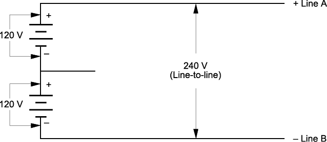
Note that polarities shown in Figure \(\PageIndex{1}\) change every 120th of a second for a 60 hertz AC power supply.
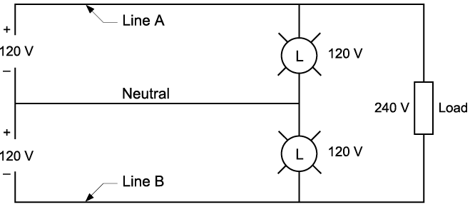
For safety reasons, it is important that circuit conductors are identified by colour:
- Insulation on the two-line conductors is usually black (or sometimes one is black and one is red).
- The neutral always has white insulation.
The neutral is also grounded (directly connected to earth) at the source of supply.
Grounding the neutral conductor
Earth is a conductor of electricity. Therefore, to reduce the hazards of electrical shock and improve safety, electrical distribution systems usually have one of the circuit conductors connected to Earth, or as we say, grounded.
In most electrical systems, the neutral conductor is grounded at the supply by directly connecting it to Earth by another conductor (called the system grounding conductor) or by an electrode. Although grounding electrical distribution systems is an elaborate topic, consider the following simplified example.
Example
The fundamental purpose of grounding is to guard against electrical shocks and fire hazards. But what makes a grounded electrical system safer? Consider an ungrounded 120 V/240 V wiring system with a fault, as shown in Figure \(\PageIndex{3}\). Theoretically, if an insulation fault occurs at a piece of equipment (so that a line conductor makes accidental contact with the metal frame), nothing should happen. However, if an accidental ground should occur and a person comes in contact with the faulty equipment and ground, that person will experience a shock of 240 V (the line-to-line voltage).
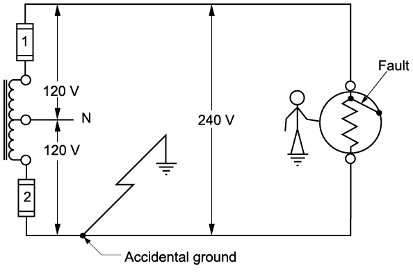
Now look at the same wiring system with the neutral purposely grounded, as shown in Figure \(\PageIndex{4}\).
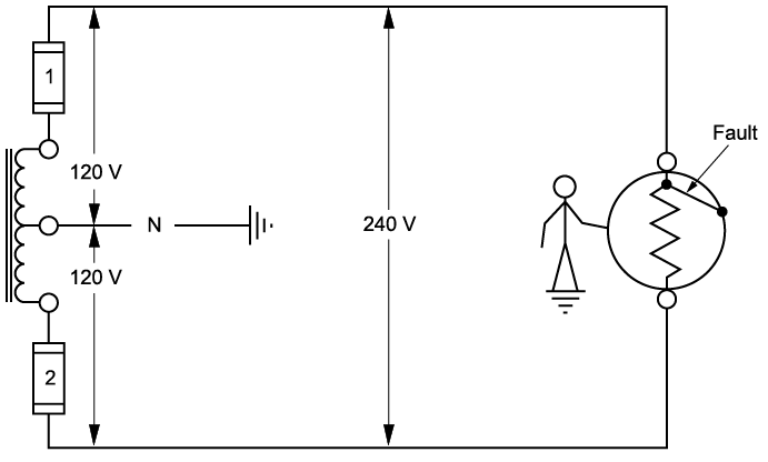
With the neutral grounded and the same equipment fault as previously described, the person coming in contact with both the metal frame of the equipment and the Earth would experience a shock of only 120 V (which is the line-to-neutral voltage). The shock voltage has been reduced by 50%.
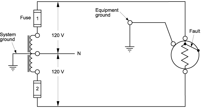
To further minimize shock hazard, not only is the wiring system grounded but also all metallic, non-current-carrying parts of the equipment are grounded by using a bonding conductor. This is an important step if maximum safety is to be achieved.
As shown in Figure \(\PageIndex{5}\), if the equipment is also grounded intentionally, then a line-to-frame fault condition offers a low-resistance path for current flow back to the system neutral. Essentially this is a line-to-neutral short circuit, which causes the circuit overcurrent device to trip, thus eliminating the shock hazard from the system.
Although properly grounded wiring systems do not eliminate shock hazard, they certainly lower the odds of being shocked!
 Now complete the Learning Task Self-Test.


