9.3: Solderless connectors
- Page ID
- 3532
\( \newcommand{\vecs}[1]{\overset { \scriptstyle \rightharpoonup} {\mathbf{#1}} } \)
\( \newcommand{\vecd}[1]{\overset{-\!-\!\rightharpoonup}{\vphantom{a}\smash {#1}}} \)
\( \newcommand{\id}{\mathrm{id}}\) \( \newcommand{\Span}{\mathrm{span}}\)
( \newcommand{\kernel}{\mathrm{null}\,}\) \( \newcommand{\range}{\mathrm{range}\,}\)
\( \newcommand{\RealPart}{\mathrm{Re}}\) \( \newcommand{\ImaginaryPart}{\mathrm{Im}}\)
\( \newcommand{\Argument}{\mathrm{Arg}}\) \( \newcommand{\norm}[1]{\| #1 \|}\)
\( \newcommand{\inner}[2]{\langle #1, #2 \rangle}\)
\( \newcommand{\Span}{\mathrm{span}}\)
\( \newcommand{\id}{\mathrm{id}}\)
\( \newcommand{\Span}{\mathrm{span}}\)
\( \newcommand{\kernel}{\mathrm{null}\,}\)
\( \newcommand{\range}{\mathrm{range}\,}\)
\( \newcommand{\RealPart}{\mathrm{Re}}\)
\( \newcommand{\ImaginaryPart}{\mathrm{Im}}\)
\( \newcommand{\Argument}{\mathrm{Arg}}\)
\( \newcommand{\norm}[1]{\| #1 \|}\)
\( \newcommand{\inner}[2]{\langle #1, #2 \rangle}\)
\( \newcommand{\Span}{\mathrm{span}}\) \( \newcommand{\AA}{\unicode[.8,0]{x212B}}\)
\( \newcommand{\vectorA}[1]{\vec{#1}} % arrow\)
\( \newcommand{\vectorAt}[1]{\vec{\text{#1}}} % arrow\)
\( \newcommand{\vectorB}[1]{\overset { \scriptstyle \rightharpoonup} {\mathbf{#1}} } \)
\( \newcommand{\vectorC}[1]{\textbf{#1}} \)
\( \newcommand{\vectorD}[1]{\overrightarrow{#1}} \)
\( \newcommand{\vectorDt}[1]{\overrightarrow{\text{#1}}} \)
\( \newcommand{\vectE}[1]{\overset{-\!-\!\rightharpoonup}{\vphantom{a}\smash{\mathbf {#1}}}} \)
\( \newcommand{\vecs}[1]{\overset { \scriptstyle \rightharpoonup} {\mathbf{#1}} } \)
\( \newcommand{\vecd}[1]{\overset{-\!-\!\rightharpoonup}{\vphantom{a}\smash {#1}}} \)
\(\newcommand{\avec}{\mathbf a}\) \(\newcommand{\bvec}{\mathbf b}\) \(\newcommand{\cvec}{\mathbf c}\) \(\newcommand{\dvec}{\mathbf d}\) \(\newcommand{\dtil}{\widetilde{\mathbf d}}\) \(\newcommand{\evec}{\mathbf e}\) \(\newcommand{\fvec}{\mathbf f}\) \(\newcommand{\nvec}{\mathbf n}\) \(\newcommand{\pvec}{\mathbf p}\) \(\newcommand{\qvec}{\mathbf q}\) \(\newcommand{\svec}{\mathbf s}\) \(\newcommand{\tvec}{\mathbf t}\) \(\newcommand{\uvec}{\mathbf u}\) \(\newcommand{\vvec}{\mathbf v}\) \(\newcommand{\wvec}{\mathbf w}\) \(\newcommand{\xvec}{\mathbf x}\) \(\newcommand{\yvec}{\mathbf y}\) \(\newcommand{\zvec}{\mathbf z}\) \(\newcommand{\rvec}{\mathbf r}\) \(\newcommand{\mvec}{\mathbf m}\) \(\newcommand{\zerovec}{\mathbf 0}\) \(\newcommand{\onevec}{\mathbf 1}\) \(\newcommand{\real}{\mathbb R}\) \(\newcommand{\twovec}[2]{\left[\begin{array}{r}#1 \\ #2 \end{array}\right]}\) \(\newcommand{\ctwovec}[2]{\left[\begin{array}{c}#1 \\ #2 \end{array}\right]}\) \(\newcommand{\threevec}[3]{\left[\begin{array}{r}#1 \\ #2 \\ #3 \end{array}\right]}\) \(\newcommand{\cthreevec}[3]{\left[\begin{array}{c}#1 \\ #2 \\ #3 \end{array}\right]}\) \(\newcommand{\fourvec}[4]{\left[\begin{array}{r}#1 \\ #2 \\ #3 \\ #4 \end{array}\right]}\) \(\newcommand{\cfourvec}[4]{\left[\begin{array}{c}#1 \\ #2 \\ #3 \\ #4 \end{array}\right]}\) \(\newcommand{\fivevec}[5]{\left[\begin{array}{r}#1 \\ #2 \\ #3 \\ #4 \\ #5 \\ \end{array}\right]}\) \(\newcommand{\cfivevec}[5]{\left[\begin{array}{c}#1 \\ #2 \\ #3 \\ #4 \\ #5 \\ \end{array}\right]}\) \(\newcommand{\mattwo}[4]{\left[\begin{array}{rr}#1 \amp #2 \\ #3 \amp #4 \\ \end{array}\right]}\) \(\newcommand{\laspan}[1]{\text{Span}\{#1\}}\) \(\newcommand{\bcal}{\cal B}\) \(\newcommand{\ccal}{\cal C}\) \(\newcommand{\scal}{\cal S}\) \(\newcommand{\wcal}{\cal W}\) \(\newcommand{\ecal}{\cal E}\) \(\newcommand{\coords}[2]{\left\{#1\right\}_{#2}}\) \(\newcommand{\gray}[1]{\color{gray}{#1}}\) \(\newcommand{\lgray}[1]{\color{lightgray}{#1}}\) \(\newcommand{\rank}{\operatorname{rank}}\) \(\newcommand{\row}{\text{Row}}\) \(\newcommand{\col}{\text{Col}}\) \(\renewcommand{\row}{\text{Row}}\) \(\newcommand{\nul}{\text{Nul}}\) \(\newcommand{\var}{\text{Var}}\) \(\newcommand{\corr}{\text{corr}}\) \(\newcommand{\len}[1]{\left|#1\right|}\) \(\newcommand{\bbar}{\overline{\bvec}}\) \(\newcommand{\bhat}{\widehat{\bvec}}\) \(\newcommand{\bperp}{\bvec^\perp}\) \(\newcommand{\xhat}{\widehat{\xvec}}\) \(\newcommand{\vhat}{\widehat{\vvec}}\) \(\newcommand{\uhat}{\widehat{\uvec}}\) \(\newcommand{\what}{\widehat{\wvec}}\) \(\newcommand{\Sighat}{\widehat{\Sigma}}\) \(\newcommand{\lt}{<}\) \(\newcommand{\gt}{>}\) \(\newcommand{\amp}{&}\) \(\definecolor{fillinmathshade}{gray}{0.9}\)Soldering is the recommended way to splice, tap, or join wires to make a rigid, permanent, weather-resistant connection. The process of soldering can be time-consuming, awkward, restrictive, and expensive.
In many applications, soldering has been replaced by special connecting devices that simplify wire joining procedures. Solderless connectors are used on both wire and cable connections. Types of solderless connectors include:
- looped-end
- twist-on
- set-screw
- crimp-on
Looped-end connectors
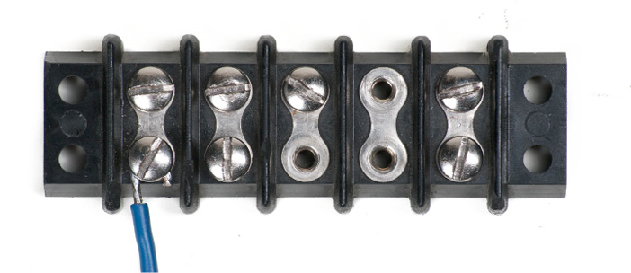
The most common solderless connection has the looped end of a wire (Figure \(\PageIndex{1}\)) held in place by a set-screw at an electrical terminal (Figure 9). Note that the direction of the loop is the same as the direction the screw is turned when it is tightened (clockwise). The screw and washer should be made of corrosion-resistant materials such as copper or brass.


Twist-on connectors
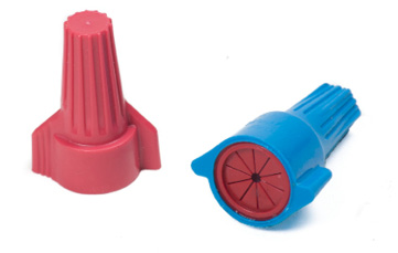
The twist-on connector is a one-piece connecting device designed to splice aluminum or copper wires. Twist-on connectors are also known as wire nuts, wire connectors, cone connectors, thimble connectors, or Marrettes. Inside the blunt, bullet-like cover of the twist-on connector is a cone-shaped spring insert that threads itself onto conductors when the connector is twisted. When the connector is twisted onto the stripped ends of wires, the wires are drawn, twisted, and squeezed into the connector’s metal insert. Electrical continuity is maintained both by the direct twisted wire-to-wire contact and by contact with the metal insert.


Wing-like extensions (Figure \(\PageIndex{5}\)) are molded into some makes of connectors to reduce operator muscle fatigue when installing a large number of the connectors.

The shell of the twist-on connector provides sufficient insulation to allow these connectors to be used in circuits carrying up to 600 V.
Twist-on wire connectors are commonly colour-coded to indicate the connector size and, hence, their capacity (Figure \(\PageIndex{6}\)). They are commonly used as an alternative to soldering conductors since they are quicker to install and allow easy removal for future modifications, unlike soldered connections.

Twist-on connectors are not often used on wire gauges thicker than AWG #10 (5.26 mm²) because such solid wires are too stiff to be reliably connected with this method. Instead, set screw connectors, clamps, or crimp connectors are used.
Set-screw connectors
Set-screw connectors (Figure 13) consist of two parts:
- a brass connector body into which wires are inserted
- an insulated cone-shaped cap that is screwed onto the brass connector

The set-screw connector is most often used as a splice inside a protected electrical box and lighting fixtures. Although set-screws are more time-consuming to install and are more expensive than twist-ons, they may offer a more secure connection than twist-on connectors.
Crimp-on connectors
A crimp-on connector is used for a permanent tight splice. The crimp-on connector (compression connection) can have one or two parts.
The two-part connector (Figure \(\PageIndex{8}\)) has a conductor retaining sleeve that is compressed by using special crimping pliers and an insulated screw cap into which the crimped retainer is inserted.
The sleeve is composed of copper or zinc-plated steel, while the cap is a high dielectric substance. The zinc-plated steel retaining sleeve should not be used with aluminum conductors, as electrolysis can occur between the metals.

These devices are available in many sizes. As with other solderless connectors, each application must carefully select the correct size two-piece crimp-on connector.
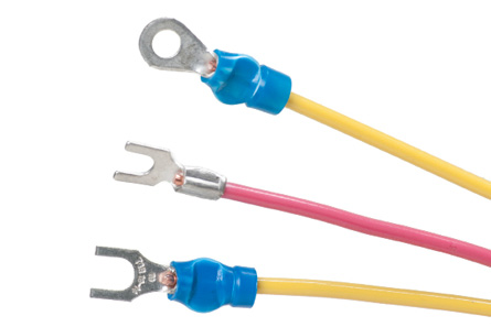
The one-part crimp-on connector (Figure \(\PageIndex{9}\)) is commonly used as a terminal lug. Both the fork and the ring-type greatly simplify connecting stranded conductors to terminal screws. The crimp-on connector sometimes has a soft, hose-like tube that is molded to the connector. The connector and the insulation are crimped together. After crimping, the insulation returns to its original form.

 Now complete the Learning Task Self-Test.


