
2.1: Combination Series and Parallel Circuits
- Page ID
- 5123

\( \newcommand{\vecs}[1]{\overset { \scriptstyle \rightharpoonup} {\mathbf{#1}} } \)
\( \newcommand{\vecd}[1]{\overset{-\!-\!\rightharpoonup}{\vphantom{a}\smash {#1}}} \)
\( \newcommand{\dsum}{\displaystyle\sum\limits} \)
\( \newcommand{\dint}{\displaystyle\int\limits} \)
\( \newcommand{\dlim}{\displaystyle\lim\limits} \)
\( \newcommand{\id}{\mathrm{id}}\) \( \newcommand{\Span}{\mathrm{span}}\)
( \newcommand{\kernel}{\mathrm{null}\,}\) \( \newcommand{\range}{\mathrm{range}\,}\)
\( \newcommand{\RealPart}{\mathrm{Re}}\) \( \newcommand{\ImaginaryPart}{\mathrm{Im}}\)
\( \newcommand{\Argument}{\mathrm{Arg}}\) \( \newcommand{\norm}[1]{\| #1 \|}\)
\( \newcommand{\inner}[2]{\langle #1, #2 \rangle}\)
\( \newcommand{\Span}{\mathrm{span}}\)
\( \newcommand{\id}{\mathrm{id}}\)
\( \newcommand{\Span}{\mathrm{span}}\)
\( \newcommand{\kernel}{\mathrm{null}\,}\)
\( \newcommand{\range}{\mathrm{range}\,}\)
\( \newcommand{\RealPart}{\mathrm{Re}}\)
\( \newcommand{\ImaginaryPart}{\mathrm{Im}}\)
\( \newcommand{\Argument}{\mathrm{Arg}}\)
\( \newcommand{\norm}[1]{\| #1 \|}\)
\( \newcommand{\inner}[2]{\langle #1, #2 \rangle}\)
\( \newcommand{\Span}{\mathrm{span}}\) \( \newcommand{\AA}{\unicode[.8,0]{x212B}}\)
\( \newcommand{\vectorA}[1]{\vec{#1}} % arrow\)
\( \newcommand{\vectorAt}[1]{\vec{\text{#1}}} % arrow\)
\( \newcommand{\vectorB}[1]{\overset { \scriptstyle \rightharpoonup} {\mathbf{#1}} } \)
\( \newcommand{\vectorC}[1]{\textbf{#1}} \)
\( \newcommand{\vectorD}[1]{\overrightarrow{#1}} \)
\( \newcommand{\vectorDt}[1]{\overrightarrow{\text{#1}}} \)
\( \newcommand{\vectE}[1]{\overset{-\!-\!\rightharpoonup}{\vphantom{a}\smash{\mathbf {#1}}}} \)
\( \newcommand{\vecs}[1]{\overset { \scriptstyle \rightharpoonup} {\mathbf{#1}} } \)
\(\newcommand{\longvect}{\overrightarrow}\)
\( \newcommand{\vecd}[1]{\overset{-\!-\!\rightharpoonup}{\vphantom{a}\smash {#1}}} \)
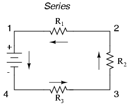
\(\newcommand{\avec}{\mathbf a}\) \(\newcommand{\bvec}{\mathbf b}\) \(\newcommand{\cvec}{\mathbf c}\) \(\newcommand{\dvec}{\mathbf d}\) \(\newcommand{\dtil}{\widetilde{\mathbf d}}\) \(\newcommand{\evec}{\mathbf e}\) \(\newcommand{\fvec}{\mathbf f}\) \(\newcommand{\nvec}{\mathbf n}\) \(\newcommand{\pvec}{\mathbf p}\) \(\newcommand{\qvec}{\mathbf q}\) \(\newcommand{\svec}{\mathbf s}\) \(\newcommand{\tvec}{\mathbf t}\) \(\newcommand{\uvec}{\mathbf u}\) \(\newcommand{\vvec}{\mathbf v}\) \(\newcommand{\wvec}{\mathbf w}\) \(\newcommand{\xvec}{\mathbf x}\) \(\newcommand{\yvec}{\mathbf y}\) \(\newcommand{\zvec}{\mathbf z}\) \(\newcommand{\rvec}{\mathbf r}\) \(\newcommand{\mvec}{\mathbf m}\) \(\newcommand{\zerovec}{\mathbf 0}\) \(\newcommand{\onevec}{\mathbf 1}\) \(\newcommand{\real}{\mathbb R}\) \(\newcommand{\twovec}[2]{\left[\begin{array}{r}#1 \\ #2 \end{array}\right]}\) \(\newcommand{\ctwovec}[2]{\left[\begin{array}{c}#1 \\ #2 \end{array}\right]}\) \(\newcommand{\threevec}[3]{\left[\begin{array}{r}#1 \\ #2 \\ #3 \end{array}\right]}\) \(\newcommand{\cthreevec}[3]{\left[\begin{array}{c}#1 \\ #2 \\ #3 \end{array}\right]}\) \(\newcommand{\fourvec}[4]{\left[\begin{array}{r}#1 \\ #2 \\ #3 \\ #4 \end{array}\right]}\) \(\newcommand{\cfourvec}[4]{\left[\begin{array}{c}#1 \\ #2 \\ #3 \\ #4 \end{array}\right]}\) \(\newcommand{\fivevec}[5]{\left[\begin{array}{r}#1 \\ #2 \\ #3 \\ #4 \\ #5 \\ \end{array}\right]}\) \(\newcommand{\cfivevec}[5]{\left[\begin{array}{c}#1 \\ #2 \\ #3 \\ #4 \\ #5 \\ \end{array}\right]}\) \(\newcommand{\mattwo}[4]{\left[\begin{array}{rr}#1 \amp #2 \\ #3 \amp #4 \\ \end{array}\right]}\) \(\newcommand{\laspan}[1]{\text{Span}\{#1\}}\) \(\newcommand{\bcal}{\cal B}\) \(\newcommand{\ccal}{\cal C}\) \(\newcommand{\scal}{\cal S}\) \(\newcommand{\wcal}{\cal W}\) \(\newcommand{\ecal}{\cal E}\) \(\newcommand{\coords}[2]{\left\{#1\right\}_{#2}}\) \(\newcommand{\gray}[1]{\color{gray}{#1}}\) \(\newcommand{\lgray}[1]{\color{lightgray}{#1}}\) \(\newcommand{\rank}{\operatorname{rank}}\) \(\newcommand{\row}{\text{Row}}\) \(\newcommand{\col}{\text{Col}}\) \(\renewcommand{\row}{\text{Row}}\) \(\newcommand{\nul}{\text{Nul}}\) \(\newcommand{\var}{\text{Var}}\) \(\newcommand{\corr}{\text{corr}}\) \(\newcommand{\len}[1]{\left|#1\right|}\) \(\newcommand{\bbar}{\overline{\bvec}}\) \(\newcommand{\bhat}{\widehat{\bvec}}\) \(\newcommand{\bperp}{\bvec^\perp}\) \(\newcommand{\xhat}{\widehat{\xvec}}\) \(\newcommand{\vhat}{\widehat{\vvec}}\) \(\newcommand{\uhat}{\widehat{\uvec}}\) \(\newcommand{\what}{\widehat{\wvec}}\) \(\newcommand{\Sighat}{\widehat{\Sigma}}\) \(\newcommand{\lt}{<}\) \(\newcommand{\gt}{>}\) \(\newcommand{\amp}{&}\) \(\definecolor{fillinmathshade}{gray}{0.9}\)With simple series circuits, all components are connected end-to-end to form only one path for electrons to flow through the circuit:
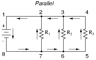
With simple parallel circuits, all components are connected between the same two sets of electrically common points, creating multiple paths for electrons to flow from one end of the battery to the other:
With each of these two basic circuit configurations, we have specific sets of rules describing voltage, current, and resistance relationships.
- Series Circuits:
- Voltage drops add to equal total voltage.
- All components share the same (equal) current.
- Resistances add to equal total resistance.
- Parallel Circuits:
- All components share the same (equal) voltage.
- Branch currents add to equal total current.
- Resistances diminish to equal total resistance.
However, if circuit components are series-connected in some parts and parallel in others, we won’t be able to apply a single set of rules to every part of that circuit. Instead, we will have to identify which parts of that circuit are series and which parts are parallel, then selectively apply series and parallel rules as necessary to determine what is happening. Take the following circuit, for instance:
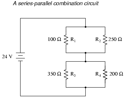
This circuit is neither simple series nor simple parallel. Rather, it contains elements of both. The current exits the bottom of the battery, splits up to travel through R3 and R4, rejoins, then splits up again to travel through R1and R2, then rejoins again to return to the top of the battery. There exists more than one path for current to travel (not series), yet there are more than two sets of electrically common points in the circuit (not parallel).
Because the circuit is a combination of both series and parallel, we cannot apply the rules for voltage, current, and resistance “across the table” to begin analysis like we could when the circuits were one way or the other. For instance, if the above circuit were simple series, we could just add up R1 through R4 to arrive at a total resistance, solve for total current, and then solve for all voltage drops. Likewise, if the above circuit were simple parallel, we could just solve for branch currents, add up branch currents to figure the total current, and then calculate total resistance from total voltage and total current. However, this circuit’s solution will be more complex.
The table will still help us manage the different values for series-parallel combination circuits, but we’ll have to be careful how and where we apply the different rules for series and parallel. Ohm’s Law, of course, still works just the same for determining values within a vertical column in the table.
If we are able to identify which parts of the circuit are series and which parts are parallel, we can analyze it in stages, approaching each part one at a time, using the appropriate rules to determine the relationships of voltage, current, and resistance. The rest of this chapter will be devoted to showing you techniques for doing this.
Process of Series-Parallel Resistor Circuit Analysis
The goal of series-parallel resistor circuit analysis is to be able to determine all voltage drops, currents, and power dissipations in a circuit. The general strategy to accomplish this goal is as follows:
- Step 1: Assess which resistors in a circuit are connected together in simple series or simple parallel.
- Step 2: Re-draw the circuit, replacing each of those series or parallel resistor combinations identified in step 1 with a single, equivalent-value resistor. If using a table to manage variables, make a new table column for each resistance equivalent.
- Step 3: Repeat steps 1 and 2 until the entire circuit is reduced to one equivalent resistor.
- Step 4: Calculate total current from total voltage and total resistance (I=E/R).
- Step 5: Taking total voltage and total current values, go back to last step in the circuit reduction process and insert those values where applicable.
- Step 6: From known resistances and total voltage / total current values from step 5, use Ohm’s Law to calculate unknown values (voltage or current) (E=IR or I=E/R).
- Step 7: Repeat steps 5 and 6 until all values for voltage and current are known in the original circuit configuration. Essentially, you will proceed step-by-step from the simplified version of the circuit back into its original, complex form, plugging in values of voltage and current where appropriate until all values of voltage and current are known.
- Step 8: Calculate power dissipations from known voltage, current, and/or resistance values.
This may sound like an intimidating process, but its much easier understood through example than through description.
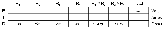
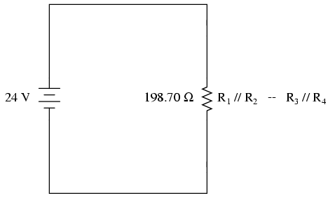
In the example circuit above, R1 and R2 are connected in a simple parallel arrangement, as are R3 and R4. Having been identified, these sections need to be converted into equivalent single resistors, and the circuit re-drawn:
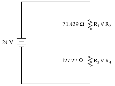
The double slash (//) symbols represent “parallel” to show that the equivalent resistor values were calculated using the 1/(1/R) formula. The 71.429 Ω resistor at the top of the circuit is the equivalent of R1 and R2 in parallel with each other. The 127.27 Ω resistor at the bottom is the equivalent of R3 and R4 in parallel with each other.
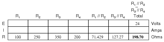
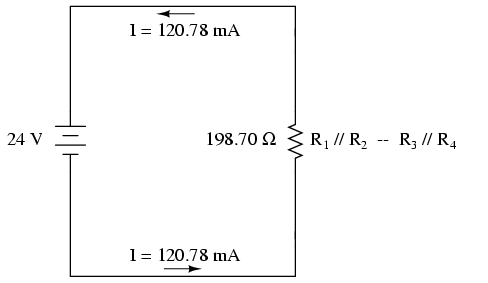
It should be apparent now that the circuit has been reduced to a simple series configuration with only two (equivalent) resistances. The final step in reduction is to add these two resistances to come up with a total circuit resistance. When we add those two equivalent resistances, we get a resistance of 198.70 Ω. Now, we can re-draw the circuit as a single equivalent resistance and add the total resistance figure to the rightmost column of our table. Note that the “Total” column has been relabeled (R1//R2—R3//R4) to indicate how it relates electrically to the other columns of figures. The “—” symbol is used here to represent “series,” just as the “//” symbol is used to represent “parallel.”
Now, total circuit current can be determined by applying Ohm’s Law (I=E/R) to the “Total” column in the table:
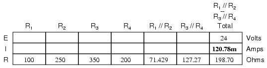
Back to our equivalent circuit drawing, our total current value of 120.78 milliamps is shown as the only current here:
Now we start to work backwards in our progression of circuit re-drawings to the original configuration. The next step is to go to the circuit where R1//R2and R3//R4 are in series:
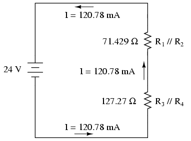
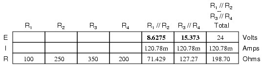
Since R1//R2 and R3//R4 are in series with each other, the current through those two sets of equivalent resistances must be the same. Furthermore, the current through them must be the same as the total current, so we can fill in our table with the appropriate current values, simply copying the current figure from the Total column to the R1//R2 and R3//R4 columns:
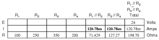
Now, knowing the current through the equivalent resistors R1//R2 and R3//R4, we can apply Ohm’s Law (E=IR) to the two right vertical columns to find voltage drops across them:
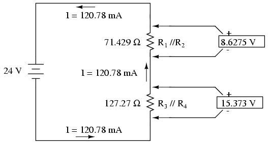
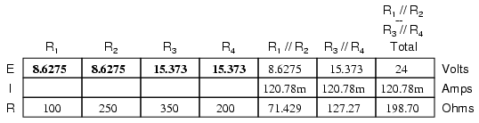
Because we know R1//R2 and R3//R4 are parallel resistor equivalents, and we know that voltage drops in parallel circuits are the same, we can transfer the respective voltage drops to the appropriate columns on the table for those individual resistors. In other words, we take another step backwards in our drawing sequence to the original configuration, and complete the table accordingly:
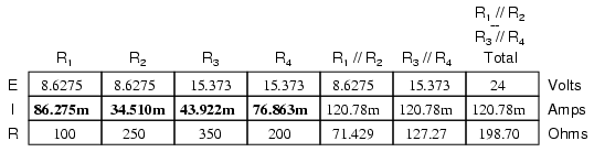
Finally, the original section of the table (columns R1 through R4) is complete with enough values to finish. Applying Ohm’s Law to the remaining vertical columns (I=E/R), we can determine the currents through R1, R2, R3, and R4individually:
Placing Voltage and Current Values into Diagrams
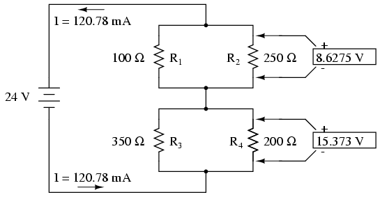
Having found all voltage and current values for this circuit, we can show those values in the schematic diagram as such:
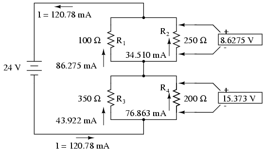
As a final check of our work, we can see if the calculated current values add up as they should to the total. Since R1 and R2 are in parallel, their combined currents should add up to the total of 120.78 mA. Likewise, since R3 and R4 are in parallel, their combined currents should also add up to the total of 120.78 mA. You can check for yourself to verify that these figures do add up as expected.