
5.8: Building Simple Resistor Circuits
- Page ID
- 719

\( \newcommand{\vecs}[1]{\overset { \scriptstyle \rightharpoonup} {\mathbf{#1}} } \)
\( \newcommand{\vecd}[1]{\overset{-\!-\!\rightharpoonup}{\vphantom{a}\smash {#1}}} \)
\( \newcommand{\id}{\mathrm{id}}\) \( \newcommand{\Span}{\mathrm{span}}\)
( \newcommand{\kernel}{\mathrm{null}\,}\) \( \newcommand{\range}{\mathrm{range}\,}\)
\( \newcommand{\RealPart}{\mathrm{Re}}\) \( \newcommand{\ImaginaryPart}{\mathrm{Im}}\)
\( \newcommand{\Argument}{\mathrm{Arg}}\) \( \newcommand{\norm}[1]{\| #1 \|}\)
\( \newcommand{\inner}[2]{\langle #1, #2 \rangle}\)
\( \newcommand{\Span}{\mathrm{span}}\)
\( \newcommand{\id}{\mathrm{id}}\)
\( \newcommand{\Span}{\mathrm{span}}\)
\( \newcommand{\kernel}{\mathrm{null}\,}\)
\( \newcommand{\range}{\mathrm{range}\,}\)
\( \newcommand{\RealPart}{\mathrm{Re}}\)
\( \newcommand{\ImaginaryPart}{\mathrm{Im}}\)
\( \newcommand{\Argument}{\mathrm{Arg}}\)
\( \newcommand{\norm}[1]{\| #1 \|}\)
\( \newcommand{\inner}[2]{\langle #1, #2 \rangle}\)
\( \newcommand{\Span}{\mathrm{span}}\) \( \newcommand{\AA}{\unicode[.8,0]{x212B}}\)
\( \newcommand{\vectorA}[1]{\vec{#1}} % arrow\)
\( \newcommand{\vectorAt}[1]{\vec{\text{#1}}} % arrow\)
\( \newcommand{\vectorB}[1]{\overset { \scriptstyle \rightharpoonup} {\mathbf{#1}} } \)
\( \newcommand{\vectorC}[1]{\textbf{#1}} \)
\( \newcommand{\vectorD}[1]{\overrightarrow{#1}} \)
\( \newcommand{\vectorDt}[1]{\overrightarrow{\text{#1}}} \)
\( \newcommand{\vectE}[1]{\overset{-\!-\!\rightharpoonup}{\vphantom{a}\smash{\mathbf {#1}}}} \)
\( \newcommand{\vecs}[1]{\overset { \scriptstyle \rightharpoonup} {\mathbf{#1}} } \)
\( \newcommand{\vecd}[1]{\overset{-\!-\!\rightharpoonup}{\vphantom{a}\smash {#1}}} \)
\(\newcommand{\avec}{\mathbf a}\) \(\newcommand{\bvec}{\mathbf b}\) \(\newcommand{\cvec}{\mathbf c}\) \(\newcommand{\dvec}{\mathbf d}\) \(\newcommand{\dtil}{\widetilde{\mathbf d}}\) \(\newcommand{\evec}{\mathbf e}\) \(\newcommand{\fvec}{\mathbf f}\) \(\newcommand{\nvec}{\mathbf n}\) \(\newcommand{\pvec}{\mathbf p}\) \(\newcommand{\qvec}{\mathbf q}\) \(\newcommand{\svec}{\mathbf s}\) \(\newcommand{\tvec}{\mathbf t}\) \(\newcommand{\uvec}{\mathbf u}\) \(\newcommand{\vvec}{\mathbf v}\) \(\newcommand{\wvec}{\mathbf w}\) \(\newcommand{\xvec}{\mathbf x}\) \(\newcommand{\yvec}{\mathbf y}\) \(\newcommand{\zvec}{\mathbf z}\) \(\newcommand{\rvec}{\mathbf r}\) \(\newcommand{\mvec}{\mathbf m}\) \(\newcommand{\zerovec}{\mathbf 0}\) \(\newcommand{\onevec}{\mathbf 1}\) \(\newcommand{\real}{\mathbb R}\) \(\newcommand{\twovec}[2]{\left[\begin{array}{r}#1 \\ #2 \end{array}\right]}\) \(\newcommand{\ctwovec}[2]{\left[\begin{array}{c}#1 \\ #2 \end{array}\right]}\) \(\newcommand{\threevec}[3]{\left[\begin{array}{r}#1 \\ #2 \\ #3 \end{array}\right]}\) \(\newcommand{\cthreevec}[3]{\left[\begin{array}{c}#1 \\ #2 \\ #3 \end{array}\right]}\) \(\newcommand{\fourvec}[4]{\left[\begin{array}{r}#1 \\ #2 \\ #3 \\ #4 \end{array}\right]}\) \(\newcommand{\cfourvec}[4]{\left[\begin{array}{c}#1 \\ #2 \\ #3 \\ #4 \end{array}\right]}\) \(\newcommand{\fivevec}[5]{\left[\begin{array}{r}#1 \\ #2 \\ #3 \\ #4 \\ #5 \\ \end{array}\right]}\) \(\newcommand{\cfivevec}[5]{\left[\begin{array}{c}#1 \\ #2 \\ #3 \\ #4 \\ #5 \\ \end{array}\right]}\) \(\newcommand{\mattwo}[4]{\left[\begin{array}{rr}#1 \amp #2 \\ #3 \amp #4 \\ \end{array}\right]}\) \(\newcommand{\laspan}[1]{\text{Span}\{#1\}}\) \(\newcommand{\bcal}{\cal B}\) \(\newcommand{\ccal}{\cal C}\) \(\newcommand{\scal}{\cal S}\) \(\newcommand{\wcal}{\cal W}\) \(\newcommand{\ecal}{\cal E}\) \(\newcommand{\coords}[2]{\left\{#1\right\}_{#2}}\) \(\newcommand{\gray}[1]{\color{gray}{#1}}\) \(\newcommand{\lgray}[1]{\color{lightgray}{#1}}\) \(\newcommand{\rank}{\operatorname{rank}}\) \(\newcommand{\row}{\text{Row}}\) \(\newcommand{\col}{\text{Col}}\) \(\renewcommand{\row}{\text{Row}}\) \(\newcommand{\nul}{\text{Nul}}\) \(\newcommand{\var}{\text{Var}}\) \(\newcommand{\corr}{\text{corr}}\) \(\newcommand{\len}[1]{\left|#1\right|}\) \(\newcommand{\bbar}{\overline{\bvec}}\) \(\newcommand{\bhat}{\widehat{\bvec}}\) \(\newcommand{\bperp}{\bvec^\perp}\) \(\newcommand{\xhat}{\widehat{\xvec}}\) \(\newcommand{\vhat}{\widehat{\vvec}}\) \(\newcommand{\uhat}{\widehat{\uvec}}\) \(\newcommand{\what}{\widehat{\wvec}}\) \(\newcommand{\Sighat}{\widehat{\Sigma}}\) \(\newcommand{\lt}{<}\) \(\newcommand{\gt}{>}\) \(\newcommand{\amp}{&}\) \(\definecolor{fillinmathshade}{gray}{0.9}\)How to Build a Simple Series Circuit
If all we wish to construct is a simple single-battery, single-resistor circuit, we may easily use alligator clip jumper wires like this:
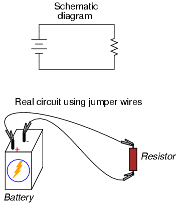
Jumper wires with “alligator” style spring clips at each end provide a safe and convenient method of electrically joining components together.
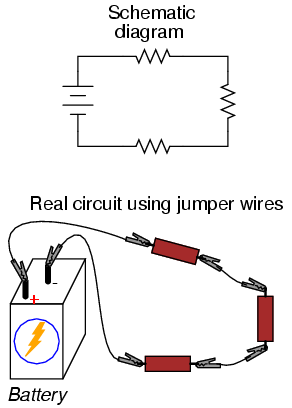
If we wanted to build a simple series circuit with one battery and three resistors, the same “point-to-point” construction technique using jumper wires could be applied:
Using a Solderless Breadboard for More Complex Circuits
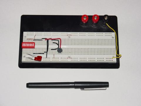
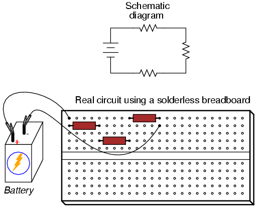
This technique, however, proves impractical for circuits much more complex than this, due to the awkwardness of the jumper wires and the physical fragility of their connections. A more common method of temporary construction for the hobbyist is the solderless breadboard, a device made of plastic with hundreds of spring-loaded connection sockets joining the inserted ends of components and/or 22-gauge solid wire pieces. A photograph of a real breadboard is shown here, followed by an illustration showing a simple series circuit constructed on one:
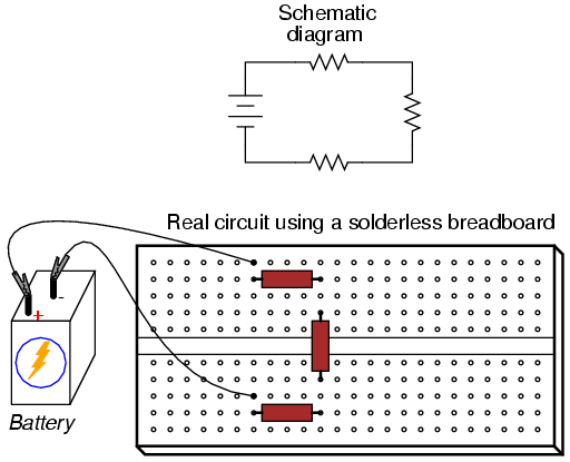
Underneath each hole in the breadboard face is a metal spring clip, designed to grasp any inserted wire or component lead. These metal spring clips are joined underneath the breadboard face, making connections between inserted leads. The connection pattern joins every five holes along a vertical column (as shown with the long axis of the breadboard situated horizontally):
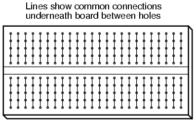
Thus, when a wire or component lead is inserted into a hole on the breadboard, there are four more holes in that column providing potential connection points to other wires and/or component leads. The result is an extremely flexible platform for constructing temporary circuits. For example, the three-resistor circuit just shown could also be built on a breadboard like this:
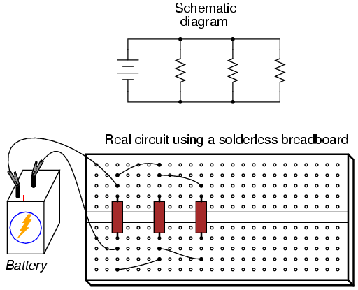
A parallel circuit is also easy to construct on a solderless breadboard:
Breadboards have their limitations, though. First and foremost, they are intended for temporary construction only. If you pick up a breadboard, turn it upside-down, and shake it, any components plugged into it are sure to loosen, and may fall out of their respective holes. Also, breadboards are limited to fairly low-current (less than 1 amp) circuits. Those spring clips have a small contact area, and thus cannot support high currents without excessive heating.
Soldering or Wire-Wrapping
For greater permanence, one might wish to choose soldering or wire-wrapping. These techniques involve fastening the components and wires to some structure providing a secure mechanical location (such as a phenolic or fiberglass board with holes drilled in it, much like a breadboard without the intrinsic spring-clip connections), and then attaching wires to the secured component leads. Soldering is a form of low-temperature welding, using a tin/lead or tin/silver alloy that melts to and electrically bonds copper objects. Wire ends soldered to component leads or to small, copper ring “pads” bonded on the surface of the circuit board serve to connect the components together. In wire wrapping, a small-gauge wire is tightly wrapped around component leads rather than soldered to leads or copper pads, the tension of the wrapped wire providing a sound mechanical and electrical junction to connect components together.
An example of a printed circuit board, or PCB, intended for hobbyist use is shown in this photograph:
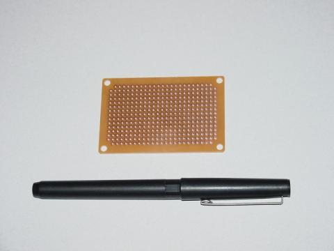
This board appears copper-side-up: the side where all the soldering is done. Each hole is ringed with a small layer of copper metal for bonding to the solder. All holes are independent of each other on this particular board, unlike the holes on a solderless breadboard which are connected together in groups of five. Printed circuit boards with the same 5-hole connection pattern as breadboards can be purchased and used for hobby circuit construction, though.
Printed Circuit Boards (PCBs)
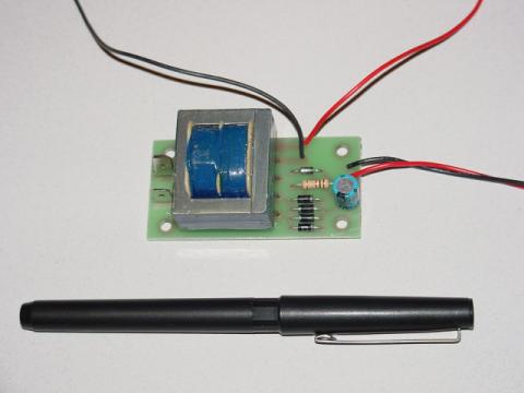
Production printed circuit boards have traces of copper laid down on the phenolic or fiberglass substrate material to form pre-engineered connection pathways which function as wires in a circuit. An example of such a board is shown here, this unit actually a “power supply” circuit designed to take 120 volt alternating current (AC) power from a household wall socket and transform it into low-voltage direct current (DC). A resistor appears on this board, the fifth component counting up from the bottom, located in the middle-right area of the board.
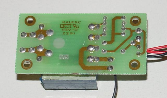
A view of this board’s underside reveals the copper “traces” connecting components together, as well as the silver-colored deposits of solder bonding the component leads to those traces:
A soldered or wire-wrapped circuit is considered permanent: that is, it is unlikely to fall apart accidently. However, these construction techniques are sometimes considered too permanent. If anyone wishes to replace a component or change the circuit in any substantial way, they must invest a fair amount of time undoing the connections. Also, both soldering and wire-wrapping require specialized tools which may not be immediately available.
Terminal Strips
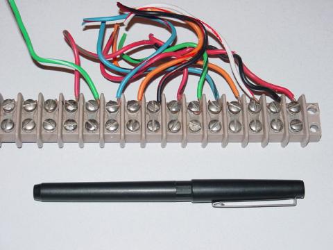
An alternative construction technique used throughout the industrial world is that of the terminal strip. Terminal strips, alternatively called barrier strips or terminal blocks, are comprised of a length of nonconducting material with several small bars of metal embedded within. Each metal bar has at least one machine screw or other fastener under which a wire or component lead may be secured. Multiple wires fastened by one screw are made electrically common to each other, as are wires fastened to multiple screws on the same bar. The following photograph shows one style of terminal strip, with a few wires attached.
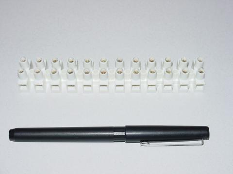
Another, smaller terminal strip is shown in this next photograph. This type, sometimes referred to as a “European” style, has recessed screws to help prevent accidental shorting between terminals by a screwdriver or other metal object:
In the following illustration, a single-battery, three-resistor circuit is shown constructed on a terminal strip:
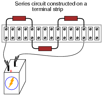
If the terminal strip uses machine screws to hold the component and wire ends, nothing but a screwdriver is needed to secure new connections or break old connections. Some terminal strips use spring-loaded clips—similar to a breadboard’s except for increased ruggedness—engaged and disengaged using a screwdriver as a push tool (no twisting involved). The electrical connections established by a terminal strip are quite robust and are considered suitable for both permanent and temporary construction.
Translating a Schematic Diagram to a Circuit Layout
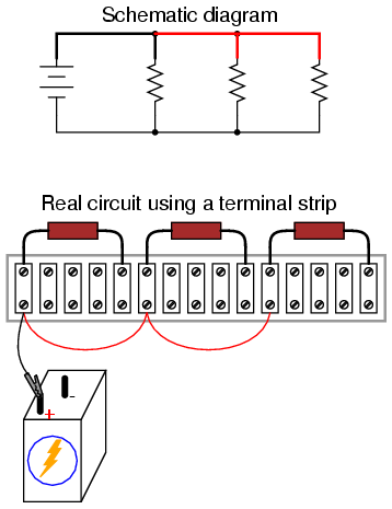
One of the essential skills for anyone interested in electricity and electronics is to be able to “translate” a schematic diagram to a real circuit layout where the components may not be oriented the same way. Schematic diagrams are usually drawn for maximum readability (excepting those few noteworthy examples sketched to create maximum confusion!), but practical circuit construction often demands a different component orientation. Building simple circuits on terminal strips is one way to develop the spatial-reasoning skill of “stretching” wires to make the same connection paths. Consider the case of a single-battery, three-resistor parallel circuit constructed on a terminal strip:
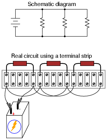
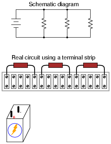
Progressing from a nice, neat, schematic diagram to the real circuit—especially when the resistors to be connected are physically arranged in a linear fashion on the terminal strip—is not obvious to many, so I’ll outline the process step-by-step. First, start with the clean schematic diagram and all components secured to the terminal strip, with no connecting wires:
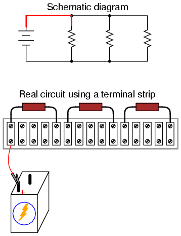
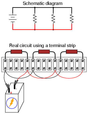
Next, trace the wire connection from one side of the battery to the first component in the schematic, securing a connecting wire between the same two points on the real circuit. I find it helpful to over-draw the schematic’s wire with another line to indicate what connections I’ve made in real life:
Continue this process, wire by wire, until all connections in the schematic diagram have been accounted for. It might be helpful to regard common wires in a SPICE-like fashion: make all connections to a common wire in the circuit as one step, making sure each and every component with a connection to that wire actually has a connection to that wire before proceeding to the next. For the next step, I’ll show how the top sides of the remaining two resistors are connected together, being common with the wire secured in the previous step:
With the top sides of all resistors (as shown in the schematic) connected together, and to the battery’s positive (+) terminal, all we have to do now is connect the bottom sides together and to the other side of the battery:
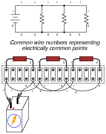
Typically in industry, all wires are labeled with number tags, and electrically common wires bear the same tag number, just as they do in a SPICE simulation. In this case, we could label the wires 1 and 2:
Another industrial convention is to modify the schematic diagram slightly so as to indicate actual wire connection points on the terminal strip. This demands a labeling system for the strip itself: a “TB” number (terminal block number) for the strip, followed by another number representing each metal bar on the strip.
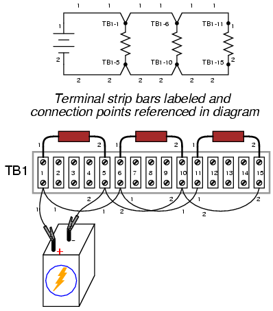
This way, the schematic may be used as a “map” to locate points in a real circuit, regardless of how tangled and complex the connecting wiring may appear to the eyes. This may seem excessive for the simple, three-resistor circuit shown here, but such detail is absolutely necessary for construction and maintenance of large circuits, especially when those circuits may span a great physical distance, using more than one terminal strip located in more than one panel or box.
Review
- A solderless breadboard is a device used to quickly assemble temporary circuits by plugging wires and components into electrically common spring-clips arranged underneath rows of holes in a plastic board.
- Soldering is a low-temperature welding process utilizing a lead/tin or tin/silver alloy to bond wires and component leads together, usually with the components secured to a fiberglass board.
- Wire-wrapping is an alternative to soldering, involving small-gauge wire tightly wrapped around component leads rather than a welded joint to connect components together.
- A terminal strip, also known as a barrier strip or terminal block is another device used to mount components and wires to build circuits. Screw terminals or heavy spring clips attached to metal bars provide connection points for the wire ends and component leads, these metal bars mounted separately to a piece of nonconducting material such as plastic, bakelite, or ceramic.