
1.5: Heat Exchangers
- Page ID
- 10933

\( \newcommand{\vecs}[1]{\overset { \scriptstyle \rightharpoonup} {\mathbf{#1}} } \)
\( \newcommand{\vecd}[1]{\overset{-\!-\!\rightharpoonup}{\vphantom{a}\smash {#1}}} \)
\( \newcommand{\id}{\mathrm{id}}\) \( \newcommand{\Span}{\mathrm{span}}\)
( \newcommand{\kernel}{\mathrm{null}\,}\) \( \newcommand{\range}{\mathrm{range}\,}\)
\( \newcommand{\RealPart}{\mathrm{Re}}\) \( \newcommand{\ImaginaryPart}{\mathrm{Im}}\)
\( \newcommand{\Argument}{\mathrm{Arg}}\) \( \newcommand{\norm}[1]{\| #1 \|}\)
\( \newcommand{\inner}[2]{\langle #1, #2 \rangle}\)
\( \newcommand{\Span}{\mathrm{span}}\)
\( \newcommand{\id}{\mathrm{id}}\)
\( \newcommand{\Span}{\mathrm{span}}\)
\( \newcommand{\kernel}{\mathrm{null}\,}\)
\( \newcommand{\range}{\mathrm{range}\,}\)
\( \newcommand{\RealPart}{\mathrm{Re}}\)
\( \newcommand{\ImaginaryPart}{\mathrm{Im}}\)
\( \newcommand{\Argument}{\mathrm{Arg}}\)
\( \newcommand{\norm}[1]{\| #1 \|}\)
\( \newcommand{\inner}[2]{\langle #1, #2 \rangle}\)
\( \newcommand{\Span}{\mathrm{span}}\) \( \newcommand{\AA}{\unicode[.8,0]{x212B}}\)
\( \newcommand{\vectorA}[1]{\vec{#1}} % arrow\)
\( \newcommand{\vectorAt}[1]{\vec{\text{#1}}} % arrow\)
\( \newcommand{\vectorB}[1]{\overset { \scriptstyle \rightharpoonup} {\mathbf{#1}} } \)
\( \newcommand{\vectorC}[1]{\textbf{#1}} \)
\( \newcommand{\vectorD}[1]{\overrightarrow{#1}} \)
\( \newcommand{\vectorDt}[1]{\overrightarrow{\text{#1}}} \)
\( \newcommand{\vectE}[1]{\overset{-\!-\!\rightharpoonup}{\vphantom{a}\smash{\mathbf {#1}}}} \)
\( \newcommand{\vecs}[1]{\overset { \scriptstyle \rightharpoonup} {\mathbf{#1}} } \)
\( \newcommand{\vecd}[1]{\overset{-\!-\!\rightharpoonup}{\vphantom{a}\smash {#1}}} \)
\(\newcommand{\avec}{\mathbf a}\) \(\newcommand{\bvec}{\mathbf b}\) \(\newcommand{\cvec}{\mathbf c}\) \(\newcommand{\dvec}{\mathbf d}\) \(\newcommand{\dtil}{\widetilde{\mathbf d}}\) \(\newcommand{\evec}{\mathbf e}\) \(\newcommand{\fvec}{\mathbf f}\) \(\newcommand{\nvec}{\mathbf n}\) \(\newcommand{\pvec}{\mathbf p}\) \(\newcommand{\qvec}{\mathbf q}\) \(\newcommand{\svec}{\mathbf s}\) \(\newcommand{\tvec}{\mathbf t}\) \(\newcommand{\uvec}{\mathbf u}\) \(\newcommand{\vvec}{\mathbf v}\) \(\newcommand{\wvec}{\mathbf w}\) \(\newcommand{\xvec}{\mathbf x}\) \(\newcommand{\yvec}{\mathbf y}\) \(\newcommand{\zvec}{\mathbf z}\) \(\newcommand{\rvec}{\mathbf r}\) \(\newcommand{\mvec}{\mathbf m}\) \(\newcommand{\zerovec}{\mathbf 0}\) \(\newcommand{\onevec}{\mathbf 1}\) \(\newcommand{\real}{\mathbb R}\) \(\newcommand{\twovec}[2]{\left[\begin{array}{r}#1 \\ #2 \end{array}\right]}\) \(\newcommand{\ctwovec}[2]{\left[\begin{array}{c}#1 \\ #2 \end{array}\right]}\) \(\newcommand{\threevec}[3]{\left[\begin{array}{r}#1 \\ #2 \\ #3 \end{array}\right]}\) \(\newcommand{\cthreevec}[3]{\left[\begin{array}{c}#1 \\ #2 \\ #3 \end{array}\right]}\) \(\newcommand{\fourvec}[4]{\left[\begin{array}{r}#1 \\ #2 \\ #3 \\ #4 \end{array}\right]}\) \(\newcommand{\cfourvec}[4]{\left[\begin{array}{c}#1 \\ #2 \\ #3 \\ #4 \end{array}\right]}\) \(\newcommand{\fivevec}[5]{\left[\begin{array}{r}#1 \\ #2 \\ #3 \\ #4 \\ #5 \\ \end{array}\right]}\) \(\newcommand{\cfivevec}[5]{\left[\begin{array}{c}#1 \\ #2 \\ #3 \\ #4 \\ #5 \\ \end{array}\right]}\) \(\newcommand{\mattwo}[4]{\left[\begin{array}{rr}#1 \amp #2 \\ #3 \amp #4 \\ \end{array}\right]}\) \(\newcommand{\laspan}[1]{\text{Span}\{#1\}}\) \(\newcommand{\bcal}{\cal B}\) \(\newcommand{\ccal}{\cal C}\) \(\newcommand{\scal}{\cal S}\) \(\newcommand{\wcal}{\cal W}\) \(\newcommand{\ecal}{\cal E}\) \(\newcommand{\coords}[2]{\left\{#1\right\}_{#2}}\) \(\newcommand{\gray}[1]{\color{gray}{#1}}\) \(\newcommand{\lgray}[1]{\color{lightgray}{#1}}\) \(\newcommand{\rank}{\operatorname{rank}}\) \(\newcommand{\row}{\text{Row}}\) \(\newcommand{\col}{\text{Col}}\) \(\renewcommand{\row}{\text{Row}}\) \(\newcommand{\nul}{\text{Nul}}\) \(\newcommand{\var}{\text{Var}}\) \(\newcommand{\corr}{\text{corr}}\) \(\newcommand{\len}[1]{\left|#1\right|}\) \(\newcommand{\bbar}{\overline{\bvec}}\) \(\newcommand{\bhat}{\widehat{\bvec}}\) \(\newcommand{\bperp}{\bvec^\perp}\) \(\newcommand{\xhat}{\widehat{\xvec}}\) \(\newcommand{\vhat}{\widehat{\vvec}}\) \(\newcommand{\uhat}{\widehat{\uvec}}\) \(\newcommand{\what}{\widehat{\wvec}}\) \(\newcommand{\Sighat}{\widehat{\Sigma}}\) \(\newcommand{\lt}{<}\) \(\newcommand{\gt}{>}\) \(\newcommand{\amp}{&}\) \(\definecolor{fillinmathshade}{gray}{0.9}\)Learning Objectives
Operate the Plant in full generating capacity and study the effect of heat exchanger surface area using the Low Pressure Feed Heater 3.
Theory
A heat exchanger is equipment in which heat exchange takes place between two working media that enter and exit at different temperatures. The main function of heat exchanger is to either remove heat from a hot working media or to add heat to the cold working media. Depending on direction of working media-fluid flow the heat exchanger is either parallel (concurrent) flow heat exchanger or counter flow heat exchanger (see Figures below).
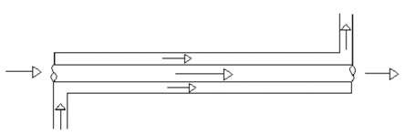
Concurrent flow.
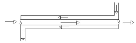
Counter current flow.
The terms are related to how the fluid flows through their respective flow passages relative to each other. If fluids flow in the same direction such as in Figure 1 it is termed a parallel flow. If fluids flow in opposite directions as in Figure 2 it is termed counter flow.
Parallel flow in heat exchangers occurs when both fluids enter the heat exchanger at their largest temperature difference. The temperature difference becomes less over the length of the heat exchanger. In the counter flow heat exchanger, fluids enter at opposite ends and therefore at different ends of the temperature scale Figure 2. The temperature difference between two fluids is relatively constant over the length of the exchanger.
The heat transfer process that occurs in any heat exchanger can be described by the following equations.


Considering the surface area involved in heat transfer, Newton’s Law of cooling states that the rate of heat loss is proportional to the difference in temperatures between the body and its surroundings and given by,

where α is called the heat transfer coefficient [W/m2K], area is taken in m2 and ΔT is the temperature difference.
Furthermore Q, heat transferred between the hot water and cold water can be calculated as follows:
}{R_{T}}")
Or
(LMTD)")
where F is the correction factor which equals 1 for this SIMLAB (it takes values between 0.5 and 1). RT is the overall resistance, U, overall heat transfer coefficient and LMTD is the Log Mean Temperature Difference.
The overall resistances can be calculated using:


Heat transfer coefficients ah and ac can be calculated using the following expression for Nusselt number for hot and cold water:
For cooling


For heating


And the LMTD is given by the following correlation where 1 and 2 presents the ends of the heat exchanger:

Heat Exchanger Effectiveness
Recall from the Boiler Efficiency Lab that efficiency is to do with minimizing waste and effectiveness to do with maximizing output. Here we define heat exchanger effectiveness as the ratio of actual heat transfer rate to the maximum possible heat transfer rate for the given temperatures.

")
Where Cmin is defined either by cold or hot fluid whichever is smaller and it is defined by:


Lab Instructions
Run the initial condition I10 230 MW_oil_auto and setup trends for
| Heat Area Factor | C34201 |
| Q | Q34228 |
| Tcold1 | T24214 |
| Tcold2 | T34214 |
| mcold | G34213 |
| Thot1 | T34204 |
| Thot2 | T34227 |
| mhot | G34203 |
- Heat Area Factor set to 0.5: Using MD420 and Variable List 4210 set C34201 to 0.5. Run the simulator with this setting for 15 minutes. Freeze and print the two trends.
- Heat Area Factor set to 1: As in step 1, set C34201 to 1. This is the default setting for the Heat Area Factor (heat transfer coefficient x area). After 15 minutes of running the simulator, freeze simulator and print the two trends.
- Heat Area Factor set to 1.5: This time, set C34201 to 1.5. Run the simulator with this setting for 15 minutes. Freeze and print the two trends.
Hints & Tips
As always, label your trends using descriptive names. In this lab, you are changing the Heat Area Factor (heat transfer coefficient x area) of LP Feed Heater 3 and comparing the temperature data. Your evaluation will be based on LMTD and Heat Exchanger Effectiveness values.
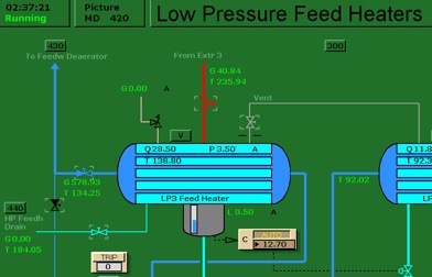
MD420 LP Feed Heater 3
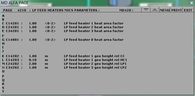
Variable List 4210.
Deliverables
Your lab report is to include the following:
- Trend plots: Supply all plots taken for this lab, make sure they are labelled properly.
- Computation: Use MATLAB or MS Excel and calculate the LMTD and Heat Exchanger effectiveness values for the 3 tests.
- Conclusion: Write a summary (max. 500 words, in a text box if using Excel) comparing your results and suggestions for further study.
Further Reading:
- Applied Thermodynamics for Engineering Technologists by T. D. Eastop and A. McConkey: Heat Transfer.