
2.1: Line styles and types
- Page ID
- 3230
\( \newcommand{\vecs}[1]{\overset { \scriptstyle \rightharpoonup} {\mathbf{#1}} } \)
\( \newcommand{\vecd}[1]{\overset{-\!-\!\rightharpoonup}{\vphantom{a}\smash {#1}}} \)
\( \newcommand{\id}{\mathrm{id}}\) \( \newcommand{\Span}{\mathrm{span}}\)
( \newcommand{\kernel}{\mathrm{null}\,}\) \( \newcommand{\range}{\mathrm{range}\,}\)
\( \newcommand{\RealPart}{\mathrm{Re}}\) \( \newcommand{\ImaginaryPart}{\mathrm{Im}}\)
\( \newcommand{\Argument}{\mathrm{Arg}}\) \( \newcommand{\norm}[1]{\| #1 \|}\)
\( \newcommand{\inner}[2]{\langle #1, #2 \rangle}\)
\( \newcommand{\Span}{\mathrm{span}}\)
\( \newcommand{\id}{\mathrm{id}}\)
\( \newcommand{\Span}{\mathrm{span}}\)
\( \newcommand{\kernel}{\mathrm{null}\,}\)
\( \newcommand{\range}{\mathrm{range}\,}\)
\( \newcommand{\RealPart}{\mathrm{Re}}\)
\( \newcommand{\ImaginaryPart}{\mathrm{Im}}\)
\( \newcommand{\Argument}{\mathrm{Arg}}\)
\( \newcommand{\norm}[1]{\| #1 \|}\)
\( \newcommand{\inner}[2]{\langle #1, #2 \rangle}\)
\( \newcommand{\Span}{\mathrm{span}}\) \( \newcommand{\AA}{\unicode[.8,0]{x212B}}\)
\( \newcommand{\vectorA}[1]{\vec{#1}} % arrow\)
\( \newcommand{\vectorAt}[1]{\vec{\text{#1}}} % arrow\)
\( \newcommand{\vectorB}[1]{\overset { \scriptstyle \rightharpoonup} {\mathbf{#1}} } \)
\( \newcommand{\vectorC}[1]{\textbf{#1}} \)
\( \newcommand{\vectorD}[1]{\overrightarrow{#1}} \)
\( \newcommand{\vectorDt}[1]{\overrightarrow{\text{#1}}} \)
\( \newcommand{\vectE}[1]{\overset{-\!-\!\rightharpoonup}{\vphantom{a}\smash{\mathbf {#1}}}} \)
\( \newcommand{\vecs}[1]{\overset { \scriptstyle \rightharpoonup} {\mathbf{#1}} } \)
\( \newcommand{\vecd}[1]{\overset{-\!-\!\rightharpoonup}{\vphantom{a}\smash {#1}}} \)
\(\newcommand{\avec}{\mathbf a}\) \(\newcommand{\bvec}{\mathbf b}\) \(\newcommand{\cvec}{\mathbf c}\) \(\newcommand{\dvec}{\mathbf d}\) \(\newcommand{\dtil}{\widetilde{\mathbf d}}\) \(\newcommand{\evec}{\mathbf e}\) \(\newcommand{\fvec}{\mathbf f}\) \(\newcommand{\nvec}{\mathbf n}\) \(\newcommand{\pvec}{\mathbf p}\) \(\newcommand{\qvec}{\mathbf q}\) \(\newcommand{\svec}{\mathbf s}\) \(\newcommand{\tvec}{\mathbf t}\) \(\newcommand{\uvec}{\mathbf u}\) \(\newcommand{\vvec}{\mathbf v}\) \(\newcommand{\wvec}{\mathbf w}\) \(\newcommand{\xvec}{\mathbf x}\) \(\newcommand{\yvec}{\mathbf y}\) \(\newcommand{\zvec}{\mathbf z}\) \(\newcommand{\rvec}{\mathbf r}\) \(\newcommand{\mvec}{\mathbf m}\) \(\newcommand{\zerovec}{\mathbf 0}\) \(\newcommand{\onevec}{\mathbf 1}\) \(\newcommand{\real}{\mathbb R}\) \(\newcommand{\twovec}[2]{\left[\begin{array}{r}#1 \\ #2 \end{array}\right]}\) \(\newcommand{\ctwovec}[2]{\left[\begin{array}{c}#1 \\ #2 \end{array}\right]}\) \(\newcommand{\threevec}[3]{\left[\begin{array}{r}#1 \\ #2 \\ #3 \end{array}\right]}\) \(\newcommand{\cthreevec}[3]{\left[\begin{array}{c}#1 \\ #2 \\ #3 \end{array}\right]}\) \(\newcommand{\fourvec}[4]{\left[\begin{array}{r}#1 \\ #2 \\ #3 \\ #4 \end{array}\right]}\) \(\newcommand{\cfourvec}[4]{\left[\begin{array}{c}#1 \\ #2 \\ #3 \\ #4 \end{array}\right]}\) \(\newcommand{\fivevec}[5]{\left[\begin{array}{r}#1 \\ #2 \\ #3 \\ #4 \\ #5 \\ \end{array}\right]}\) \(\newcommand{\cfivevec}[5]{\left[\begin{array}{c}#1 \\ #2 \\ #3 \\ #4 \\ #5 \\ \end{array}\right]}\) \(\newcommand{\mattwo}[4]{\left[\begin{array}{rr}#1 \amp #2 \\ #3 \amp #4 \\ \end{array}\right]}\) \(\newcommand{\laspan}[1]{\text{Span}\{#1\}}\) \(\newcommand{\bcal}{\cal B}\) \(\newcommand{\ccal}{\cal C}\) \(\newcommand{\scal}{\cal S}\) \(\newcommand{\wcal}{\cal W}\) \(\newcommand{\ecal}{\cal E}\) \(\newcommand{\coords}[2]{\left\{#1\right\}_{#2}}\) \(\newcommand{\gray}[1]{\color{gray}{#1}}\) \(\newcommand{\lgray}[1]{\color{lightgray}{#1}}\) \(\newcommand{\rank}{\operatorname{rank}}\) \(\newcommand{\row}{\text{Row}}\) \(\newcommand{\col}{\text{Col}}\) \(\renewcommand{\row}{\text{Row}}\) \(\newcommand{\nul}{\text{Nul}}\) \(\newcommand{\var}{\text{Var}}\) \(\newcommand{\corr}{\text{corr}}\) \(\newcommand{\len}[1]{\left|#1\right|}\) \(\newcommand{\bbar}{\overline{\bvec}}\) \(\newcommand{\bhat}{\widehat{\bvec}}\) \(\newcommand{\bperp}{\bvec^\perp}\) \(\newcommand{\xhat}{\widehat{\xvec}}\) \(\newcommand{\vhat}{\widehat{\vvec}}\) \(\newcommand{\uhat}{\widehat{\uvec}}\) \(\newcommand{\what}{\widehat{\wvec}}\) \(\newcommand{\Sighat}{\widehat{\Sigma}}\) \(\newcommand{\lt}{<}\) \(\newcommand{\gt}{>}\) \(\newcommand{\amp}{&}\) \(\definecolor{fillinmathshade}{gray}{0.9}\)Standard lines have been developed so that every drawing or sketch conveys the same meaning to everyone. In order to convey that meaning, the lines used in technical drawings have both a definite pattern and a definite thickness. Some lines are complete, and others are broken. Some lines are thick, and others are thin. A visible line, for example, is used to show the edges (or “outline”) of an object and to make it stand out for easy reading. This line is made thick and dark. On the other hand, a center line, which locates the precise center of a hole or shaft, is drawn thin and made with long and short dashes. This makes it easily distinguishable from the visible line.
When you draw, use a fairly sharp pencil of the correct grade and try to maintain an even, consistent pressure to make it easier for you to produce acceptable lines (Figure \(\PageIndex{1}\)). Study the line thicknesses (or “line weights”) shown in Figure \(\PageIndex{2}\) and practice making them.
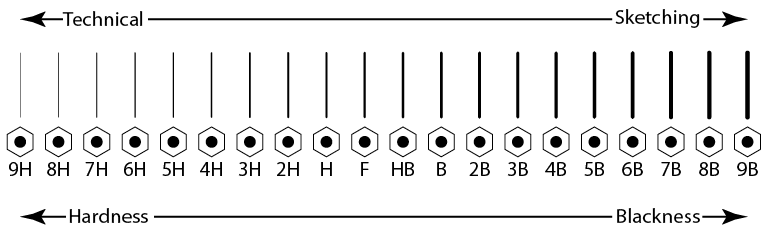
Figure \(\PageIndex{1}\): Lead grade and usage
In computer drafting, the line shape remains the same, but line thickness may not vary as it does in manually created drawings. Some lines, such as center lines, may not cross in the same manner as in a manual drawing. For most computer drafting, line thickness is not important.
| Type | Weight | Line | Description |
| Object line Margin line |
Heavy |  |
Solid line to show visible shapes, edges, and outlines. |
| Hidden body line | Medium |  |
Broken lines of long and short dashes to show hidden object lines not visible to the eye. |
| Phantom line | Light |  |
Broken line of short dashes to show alternate positions or movement of a part. |
| Section line | Light | 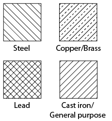 |
Unbroken lines arranged in a pattern, usually straight and at a 45° diagonal. |
| Projection line | Light |  |
Unbroken lines that extend away from the object or feature for emphasis. |
| center line | Light |  |
Broken lines of long and short dashes to show the center of an object. |
| Extension line/ Dimension line |
Light | 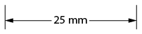 |
Extension lines are small lines that extend outward from an object or feature. Dimension lines span between the extension lines with arrowheads and a given dimension. |
| Leader line | Light |  |
Unbroken line usually drawn at an angle, often with a “dogleg” and an arrowhead. A dot is used in place of an arrowhead where a surface is referenced. Usually accompanied by a label. |
| Cutting plane line |
Heavy | 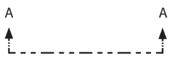 |
Broken line of one long and two short dashes to show an imaginary cross-section. The arrowheads show the direction from where the cross-section is viewed. A corresponding image will show the view of A. |
| Break lines for wood and metal |
Heavy | 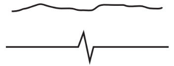 |
Unbroken freehand or straight zig-zag lines to abbreviate longer spans of wood or metal. |
| Break lines for piping |
Heavy | 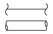 |
Curled lines to abbreviate a longer span of pipe. |
Figure \(\PageIndex{2}\): Weight of lines
To properly read and interpret drawings, you must know the meaning of each line and understand how each is used to construct a drawing. The ten most common are often referred to as the “alphabet of lines.” Let’s look at an explanation and example of each type.
Object lines
Object lines (Figure \(\PageIndex{3}\)) are the most common lines used in drawings. These thick, solid lines show the visible edges, corners, and surfaces of a part. Object lines stand out on the drawing and clearly define the outline and features of the object.
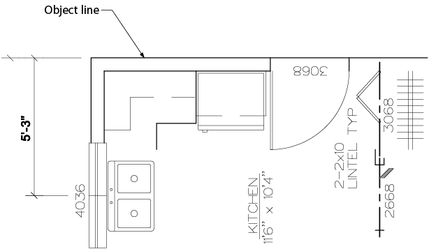
Figure \(\PageIndex{3}\): Object lines
Hidden lines
Hidden lines (Figure \(\PageIndex{4}\)) are used to show edges and surfaces that are not visible in a view. These lines are drawn as thin, evenly-spaced dashes. A surface or edge that is shown in one view with an object line will be shown in another view with a hidden line.
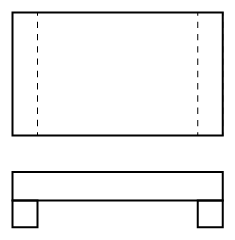
Figure \(\PageIndex{4}\): Hidden lines
Center lines
Center lines (Figure \(\PageIndex{5}\)) are used in drawings for several different applications. The meaning of a center line is normally determined by how it is used. center lines are thin, alternating long and short dashes that are generally used to show hole centers and center positions of rounded features, such as arcs and radii. Arcs are sections of a circle, and radii are rounded corners or edges of a part. center lines can also show the symmetry of an object.
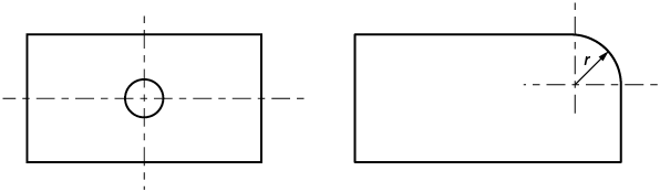
Figure \(\PageIndex{5}\): Center lines
Dimension and extension lines
Dimension and extension lines (Figure \(\PageIndex{6}\)) are thin, solid lines that show the direction, length, and limits of the dimensions of a part. Dimension lines are drawn with an arrowhead at both ends.
Extension lines are drawn close to, but never touching, the edges or surface they limit. They should be perpendicular, or at right angles, to the dimension line. The length of extension lines is generally suited to the number of dimensions they limit.
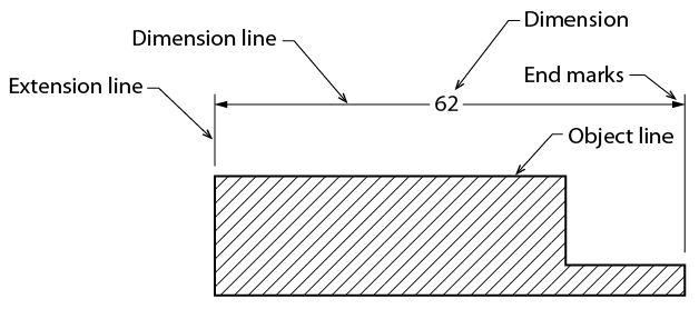
Figure \(\PageIndex{6}\): Dimension and extension lines
Leader lines
Leader lines (Figure \(\PageIndex{7}\)) show information such as dimensional notes, material specifications, and process notes. These lines are normally drawn as thin, solid lines with an arrowhead at one end. They are bent or angled at the start but should always end horizontally at the notation. When leader lines reference a surface, a dot is used instead of an arrowhead.
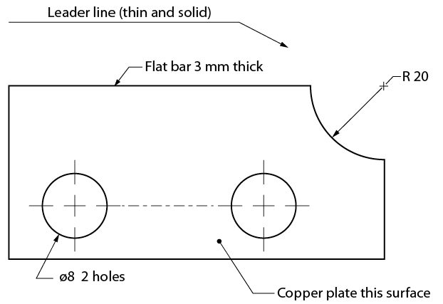
Figure \(\PageIndex{7}\): Leader lines
Note that the symbol ø is used to indicate a diameter rather than the abbreviation “DIA.” The number that immediately follows this symbol is the diameter of the hole, followed by the number of holes that must be drilled to that dimension.
Phantom lines
Like center lines, phantom lines (Figure \(\PageIndex{8}\)) are used for several purposes in blueprints. Phantom lines are used to show alternate positions for moving parts and the positions of related or adjacent parts and to eliminate repeated details. Phantom lines are drawn as thin, alternating long dashes separated by two short dashes.
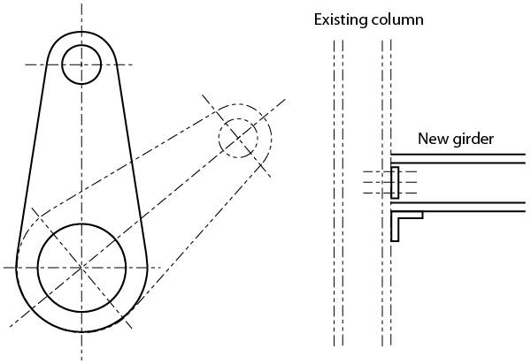
Figure \(\PageIndex{8}\): Phantom lines
Cutting plane lines
Cutting plane lines (Figure \(\PageIndex{9}\)) show the location and path of imaginary cuts made through parts to show internal details. In most cases, sectional views (or views that show complicated internal details of a part) are indicated by using a cutting plane line. These lines are thick, alternating long lines separated by two short dashes. The arrowheads at each end show the viewing direction of the related sectional view. The two main types of cutting plane lines are straight and offset.
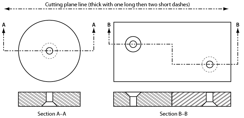
Figure \(\PageIndex{9}\): Cutting plane lines
Section lines
Section lines, also known as sectional lining, (Figure \(\PageIndex{10}\))indicate the surfaces in a sectional view as they would appear if the part were actually cut along the cutting plane line. These are solid lines that are normally drawn at 45-degree angles. Different symbols are used to represent different types of materials.
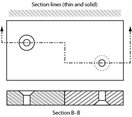
Figure \(\PageIndex{10}\): Section lines combined with cutting plane lines
Break lines
Break lines are drawn to show that a part has been shortened to reduce its size on the drawing. The two variations of break lines common to blueprints are the long break line and the short break line (Figure \(\PageIndex{11}\)). Long break lines are thin solid lines that have zigzags to indicate a break. Short break lines are thick, wavy solid lines that are drawn freehand. When either of these break lines is used to shorten an object, you can assume that the section removed from the part is identical to the portions shown on either side of the break.
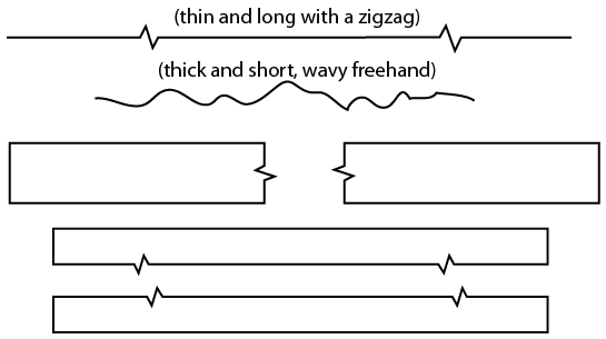
Figure \(\PageIndex{11}\): Break lines