
1.3: Unit 2: Speeds, Feeds, and Tapping
- Page ID
- 2270
\( \newcommand{\vecs}[1]{\overset { \scriptstyle \rightharpoonup} {\mathbf{#1}} } \)
\( \newcommand{\vecd}[1]{\overset{-\!-\!\rightharpoonup}{\vphantom{a}\smash {#1}}} \)
\( \newcommand{\id}{\mathrm{id}}\) \( \newcommand{\Span}{\mathrm{span}}\)
( \newcommand{\kernel}{\mathrm{null}\,}\) \( \newcommand{\range}{\mathrm{range}\,}\)
\( \newcommand{\RealPart}{\mathrm{Re}}\) \( \newcommand{\ImaginaryPart}{\mathrm{Im}}\)
\( \newcommand{\Argument}{\mathrm{Arg}}\) \( \newcommand{\norm}[1]{\| #1 \|}\)
\( \newcommand{\inner}[2]{\langle #1, #2 \rangle}\)
\( \newcommand{\Span}{\mathrm{span}}\)
\( \newcommand{\id}{\mathrm{id}}\)
\( \newcommand{\Span}{\mathrm{span}}\)
\( \newcommand{\kernel}{\mathrm{null}\,}\)
\( \newcommand{\range}{\mathrm{range}\,}\)
\( \newcommand{\RealPart}{\mathrm{Re}}\)
\( \newcommand{\ImaginaryPart}{\mathrm{Im}}\)
\( \newcommand{\Argument}{\mathrm{Arg}}\)
\( \newcommand{\norm}[1]{\| #1 \|}\)
\( \newcommand{\inner}[2]{\langle #1, #2 \rangle}\)
\( \newcommand{\Span}{\mathrm{span}}\) \( \newcommand{\AA}{\unicode[.8,0]{x212B}}\)
\( \newcommand{\vectorA}[1]{\vec{#1}} % arrow\)
\( \newcommand{\vectorAt}[1]{\vec{\text{#1}}} % arrow\)
\( \newcommand{\vectorB}[1]{\overset { \scriptstyle \rightharpoonup} {\mathbf{#1}} } \)
\( \newcommand{\vectorC}[1]{\textbf{#1}} \)
\( \newcommand{\vectorD}[1]{\overrightarrow{#1}} \)
\( \newcommand{\vectorDt}[1]{\overrightarrow{\text{#1}}} \)
\( \newcommand{\vectE}[1]{\overset{-\!-\!\rightharpoonup}{\vphantom{a}\smash{\mathbf {#1}}}} \)
\( \newcommand{\vecs}[1]{\overset { \scriptstyle \rightharpoonup} {\mathbf{#1}} } \)
\( \newcommand{\vecd}[1]{\overset{-\!-\!\rightharpoonup}{\vphantom{a}\smash {#1}}} \)
\(\newcommand{\avec}{\mathbf a}\) \(\newcommand{\bvec}{\mathbf b}\) \(\newcommand{\cvec}{\mathbf c}\) \(\newcommand{\dvec}{\mathbf d}\) \(\newcommand{\dtil}{\widetilde{\mathbf d}}\) \(\newcommand{\evec}{\mathbf e}\) \(\newcommand{\fvec}{\mathbf f}\) \(\newcommand{\nvec}{\mathbf n}\) \(\newcommand{\pvec}{\mathbf p}\) \(\newcommand{\qvec}{\mathbf q}\) \(\newcommand{\svec}{\mathbf s}\) \(\newcommand{\tvec}{\mathbf t}\) \(\newcommand{\uvec}{\mathbf u}\) \(\newcommand{\vvec}{\mathbf v}\) \(\newcommand{\wvec}{\mathbf w}\) \(\newcommand{\xvec}{\mathbf x}\) \(\newcommand{\yvec}{\mathbf y}\) \(\newcommand{\zvec}{\mathbf z}\) \(\newcommand{\rvec}{\mathbf r}\) \(\newcommand{\mvec}{\mathbf m}\) \(\newcommand{\zerovec}{\mathbf 0}\) \(\newcommand{\onevec}{\mathbf 1}\) \(\newcommand{\real}{\mathbb R}\) \(\newcommand{\twovec}[2]{\left[\begin{array}{r}#1 \\ #2 \end{array}\right]}\) \(\newcommand{\ctwovec}[2]{\left[\begin{array}{c}#1 \\ #2 \end{array}\right]}\) \(\newcommand{\threevec}[3]{\left[\begin{array}{r}#1 \\ #2 \\ #3 \end{array}\right]}\) \(\newcommand{\cthreevec}[3]{\left[\begin{array}{c}#1 \\ #2 \\ #3 \end{array}\right]}\) \(\newcommand{\fourvec}[4]{\left[\begin{array}{r}#1 \\ #2 \\ #3 \\ #4 \end{array}\right]}\) \(\newcommand{\cfourvec}[4]{\left[\begin{array}{c}#1 \\ #2 \\ #3 \\ #4 \end{array}\right]}\) \(\newcommand{\fivevec}[5]{\left[\begin{array}{r}#1 \\ #2 \\ #3 \\ #4 \\ #5 \\ \end{array}\right]}\) \(\newcommand{\cfivevec}[5]{\left[\begin{array}{c}#1 \\ #2 \\ #3 \\ #4 \\ #5 \\ \end{array}\right]}\) \(\newcommand{\mattwo}[4]{\left[\begin{array}{rr}#1 \amp #2 \\ #3 \amp #4 \\ \end{array}\right]}\) \(\newcommand{\laspan}[1]{\text{Span}\{#1\}}\) \(\newcommand{\bcal}{\cal B}\) \(\newcommand{\ccal}{\cal C}\) \(\newcommand{\scal}{\cal S}\) \(\newcommand{\wcal}{\cal W}\) \(\newcommand{\ecal}{\cal E}\) \(\newcommand{\coords}[2]{\left\{#1\right\}_{#2}}\) \(\newcommand{\gray}[1]{\color{gray}{#1}}\) \(\newcommand{\lgray}[1]{\color{lightgray}{#1}}\) \(\newcommand{\rank}{\operatorname{rank}}\) \(\newcommand{\row}{\text{Row}}\) \(\newcommand{\col}{\text{Col}}\) \(\renewcommand{\row}{\text{Row}}\) \(\newcommand{\nul}{\text{Nul}}\) \(\newcommand{\var}{\text{Var}}\) \(\newcommand{\corr}{\text{corr}}\) \(\newcommand{\len}[1]{\left|#1\right|}\) \(\newcommand{\bbar}{\overline{\bvec}}\) \(\newcommand{\bhat}{\widehat{\bvec}}\) \(\newcommand{\bperp}{\bvec^\perp}\) \(\newcommand{\xhat}{\widehat{\xvec}}\) \(\newcommand{\vhat}{\widehat{\vvec}}\) \(\newcommand{\uhat}{\widehat{\uvec}}\) \(\newcommand{\what}{\widehat{\wvec}}\) \(\newcommand{\Sighat}{\widehat{\Sigma}}\) \(\newcommand{\lt}{<}\) \(\newcommand{\gt}{>}\) \(\newcommand{\amp}{&}\) \(\definecolor{fillinmathshade}{gray}{0.9}\)Objective
After completing this unit, you should be able to:
- Identify and select vertical milling machine setups and operations for a variety of machining tasks.
- Select a proper cutting speed for different types of materials.
- Calculate cutting speeds and feeds for end milling operations.
- Explain how to correctly set up for power feed tapping.
Cutting Speed
Cutting speed is defined as the speed at the outside edge of the tool as it is cutting. This is also known as surface speed. Surface speed, surface footage, and surface area are all directly related. If two tools of different sizes are turning at the same revolutions per minute (RPM), the larger tool has a greater surface speed. Surface speed is measured in surface feet per minute (SFM). All cutting tools work on the surface footage principle. Cutting speeds depend primarily on the kind of material you are cutting and the kind of cutting tool you are using. The hardness of the work material has a great deal to do with the recommended cutting speed. The harder the work material, the slower the cutting speed. The softer the work material, the faster the recommended cutting speed (See Figure 1).
Steel Iron Aluminum Lead
Figure 1: Increasing Cutting Speed Based on work material hardness
The hardness of the cutting tool material will also have a great deal to do with the recommended cutting speed. The harder the drill, the faster the cutting speed. The softer the drill, the slower the recommended cutting speed (See Figure 2).
Carbon Steel High Speed Steel Carbide
Figure 2: Increasing Cutting Speed Based on Cutting tool hardness
Table 1: Cutting Speeds for Material Types
| Type of Material | Cutting Speed (SFM) |
|---|---|
| Low Carbon Steel | 40-140 |
| Medium Carbon Steel | 70-120 |
| High Carbon Steel | 65-100 |
| Free-machining Steel | 100-150 |
| Stainless Steel, C1 302, 304 | 60 |
| Stainless Steel, C1 310, 316 | 70 |
| Stainless Steel, C1 410 | 100 |
| Stainless Steel, C1 416 | 140 |
| Stainless Steel, C1 17-4, pH | 50 |
| Alloy Steel, SAE 4130, 4140 | 70 |
| Alloy Steel, SAE 4030 | 90 |
| Tool Steel | 40-70 |
| Cast Iron–Regular | 80-120 |
| Cast Iron–Hard | 5-30 |
| Gray Cast Iron | 50-80 |
| Aluminum Alloys | 300-400 |
| Nickel Alloy, Monel 400 | 40-60 |
| Nickel Alloy, Monel K500 | 30-60 |
| Nickel Alloy, Inconel | 5-10 |
| Cobalt Base Alloys | 5-10 |
| Titanium Alloy | 20-60 |
| Unalloyed Titanium | 35-55 |
| Copper | 100-500 |
| Bronze–Regular | 90-150 |
| Bronze–Hard | 30-70 |
| Zirconium | 70-90 |
| Brass and Aluminum | 200-350 |
| Silicon Free Non-Metallics | 100-300 |
| Silicon Containing Non-Metallics | 30-70 |
Spindle Speed
Once the SFM for a given material and tool is determined, the spindle can be calculated since this value is dependent on cutting speed and tool diameter.
RPM = (CS x 4) / D
Where:
- RPM = Revolutions per minute.
- CS = Cutter speed in SFM.
- D = Tool Diameter in inches.
Milling Feed
The feed (milling machine feed) can be defined as the distance in inches per minute that the work moves into the cutter.
On the milling machines we have here at LBCC, the feed is independent of the spindle speed. This is a good arrangement and it permits faster feeds for larger, slowly rotating cutters.
The feed rate used on a milling machine depends on the following factors:
- The depth and width of cut.
- The type of cutter.
- The sharpness of the cutter.
- The workpiece material.
- The strength and uniformity of the workpiece.
- The finish required.
- The accuracy required.
- The power and rigidity of the machine, the holding device, and the tooling setup.
Feed per Tooth
Feed per tooth, is the amount of material that should be removed by each tooth of the cutter as it revolves and advances into the work.
As the work advances into the cutter, each tooth of the cutter advances into the work an equal amount producing chips of equal thickness.
This chip thickness or feed per tooth, along with the number of teeth in the cutter, form the basis for determining the rate of feed.
The ideal feed rate for milling is measured in inches per minute (IPM) and is calculated by this formula:
IPM = F x N x RPM
Where:
- IPM = feed rate in inches per minute
- F = feed per tooth
- N = number of teeth
- RPM = revolutions per minute
For Example:
Feeds for end mills used in vertical milling machines range from .001 to .002 in. feed per tooth for very small diameter cutters on steel work material to .010 in. feed per tooth for large cutters in aluminum workpieces. Since the cutting speed for mild steel is 90, the RPM for a 3/8” high-speed, two flute end mill is
RPM = CS x 4 / D = 90 x 4 / (3/8) = 360 /.375 = 960 RPM
To calculate the feed rate, we will select .002 inches per tooth
IPM = F x N x RPM = .002 x 2 x 960 = 3.84 IPM
Machine Feed
The machine movement that causes a cutting tool to cut into or along the surface of a workpiece is called feed.
The amount of feed is usually measured in thousandths of an inch in metal cutting.
Feeds are expressed in slightly different ways on various types of machines.
Drilling machines that have power feeds are designed to advance the drill a given amount for each revolution of the spindle. If we set the machine to feed at .006” the machine will feed .006” for every revolution of the spindle. This is expressed as (IPR) inches per revolution
Tapping Procedures
Good Practices:
Using Tap Guides
Tap guides are an integral part in making a usable and straight thread. When using the lathe or the mill, the tap is already straight and centered. When manually aligning a tap, be careful, as a 90° tap guide is much more accurate than the human eye.
Using Oil
When drilling and tapping, it is crucial to use oil. It keeps the bits from squealing, makes the cut smoother, cleans out the chips, and keeps the drill and stock from overheating.
Pecking
Pecking helps ensure that bits don’t overheat and break when using them to drill or tap. Peck drilling involves drilling partway through a part, then retracting it to remove chips, simultaneously allowing the piece to cool. Rotating the handle a full turn then back a half turn is common practice. Whenever the bit or tap is backed out, remove as many chips as possible and add oil to the surface between the drill or tap and the workpiece.
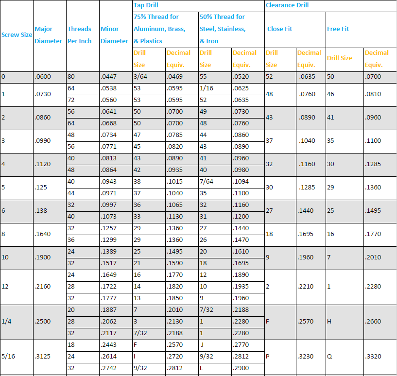
Hand Tapping Procedure
- Select a drill size from the chart.
When choosing a tap size, this chart is the first place to look.


- If necessary, add a chamfer to the hole before tapping.
Chamfers and countersinks are additional features that are sometimes desired for screws. For best results, the speed of the spindle should be between 150 and 250 rpm. - Get a tap guide.
The hole is now ready to tap. To do this, use the taps and guide blocks near the manual mills. The guide blocks will have several holes for different sized taps. Select the one closest to the size of the tap being used and place it over the drilled hole. - Tap the threads.
Peck tap using the tap wrenches. Apply gentle pressure while turning the wrench a complete turn in, then a half-turn out. Peck tap to the desired depth. - Complete the tap.
If the tap does not go any further or the desired depth has been reached, release pressure on the tap; it has likely bottomed out. Remove the tap from the hole.Applying any more pressure is likely to break the tap. The smaller the tap, the more likely it is to break.
Power Feed Tapping Procedure (Vertical Mill)
- Power feed tapping is similar to hand tapping. Instead of tapping by hand, however, use the vertical mill to tap the workpiece.
- Before starting the machine, change the mill to low gear.
- Release the quill lock and move the quill to the lowest it can go. This ensures that there is sufficient space to tap to the desired depth.
- Turn the spindle on FORWARD and set the spindle speed to 60 RPM.
- Feed the tap down. When the tap grabs the stock, it will automatically feed itself into the hole.
- When the desired depth has been reached, quickly flip the spindle direction switch from forward to reverse. This will reverse the direction of the tap and remove it from the hole. Reversing the direction in one fluid motion will prevent damage to the tapped hole and the tap.
- Turn off the machine.
- Clean the tapped hole, tap, and power feed machine before leaving.
UNIT TEST
- Explain cutting speeds for harder and softer materials.
- What is the cutting speed for Tool Steel and Aluminum?
- Calculate the RPM for a ½ in. diameter HSS end mill to machine aluminum.
- Calculate the feed rate for a three-flute tool. Use the RPM from Question 3.
- Calculate the RPM for a ¾ in. diameter HSS end mill to machine bronze.
- Calculate the feed rate for two-flute ½ in. diameter carbide end mill to machine low-carbon steel.
- What is the purpose of pecking when using them to drill or tap?
- Select a proper drill size for 5/16 – 24 tap.
- Why are cutting fluids used?
- Describe the difference between hand and power feed tapping.