
2.6: Unit 6: Lathe Threading
- Page ID
- 2278
\( \newcommand{\vecs}[1]{\overset { \scriptstyle \rightharpoonup} {\mathbf{#1}} } \)
\( \newcommand{\vecd}[1]{\overset{-\!-\!\rightharpoonup}{\vphantom{a}\smash {#1}}} \)
\( \newcommand{\dsum}{\displaystyle\sum\limits} \)
\( \newcommand{\dint}{\displaystyle\int\limits} \)
\( \newcommand{\dlim}{\displaystyle\lim\limits} \)
\( \newcommand{\id}{\mathrm{id}}\) \( \newcommand{\Span}{\mathrm{span}}\)
( \newcommand{\kernel}{\mathrm{null}\,}\) \( \newcommand{\range}{\mathrm{range}\,}\)
\( \newcommand{\RealPart}{\mathrm{Re}}\) \( \newcommand{\ImaginaryPart}{\mathrm{Im}}\)
\( \newcommand{\Argument}{\mathrm{Arg}}\) \( \newcommand{\norm}[1]{\| #1 \|}\)
\( \newcommand{\inner}[2]{\langle #1, #2 \rangle}\)
\( \newcommand{\Span}{\mathrm{span}}\)
\( \newcommand{\id}{\mathrm{id}}\)
\( \newcommand{\Span}{\mathrm{span}}\)
\( \newcommand{\kernel}{\mathrm{null}\,}\)
\( \newcommand{\range}{\mathrm{range}\,}\)
\( \newcommand{\RealPart}{\mathrm{Re}}\)
\( \newcommand{\ImaginaryPart}{\mathrm{Im}}\)
\( \newcommand{\Argument}{\mathrm{Arg}}\)
\( \newcommand{\norm}[1]{\| #1 \|}\)
\( \newcommand{\inner}[2]{\langle #1, #2 \rangle}\)
\( \newcommand{\Span}{\mathrm{span}}\) \( \newcommand{\AA}{\unicode[.8,0]{x212B}}\)
\( \newcommand{\vectorA}[1]{\vec{#1}} % arrow\)
\( \newcommand{\vectorAt}[1]{\vec{\text{#1}}} % arrow\)
\( \newcommand{\vectorB}[1]{\overset { \scriptstyle \rightharpoonup} {\mathbf{#1}} } \)
\( \newcommand{\vectorC}[1]{\textbf{#1}} \)
\( \newcommand{\vectorD}[1]{\overrightarrow{#1}} \)
\( \newcommand{\vectorDt}[1]{\overrightarrow{\text{#1}}} \)
\( \newcommand{\vectE}[1]{\overset{-\!-\!\rightharpoonup}{\vphantom{a}\smash{\mathbf {#1}}}} \)
\( \newcommand{\vecs}[1]{\overset { \scriptstyle \rightharpoonup} {\mathbf{#1}} } \)
\(\newcommand{\longvect}{\overrightarrow}\)
\( \newcommand{\vecd}[1]{\overset{-\!-\!\rightharpoonup}{\vphantom{a}\smash {#1}}} \)
\(\newcommand{\avec}{\mathbf a}\) \(\newcommand{\bvec}{\mathbf b}\) \(\newcommand{\cvec}{\mathbf c}\) \(\newcommand{\dvec}{\mathbf d}\) \(\newcommand{\dtil}{\widetilde{\mathbf d}}\) \(\newcommand{\evec}{\mathbf e}\) \(\newcommand{\fvec}{\mathbf f}\) \(\newcommand{\nvec}{\mathbf n}\) \(\newcommand{\pvec}{\mathbf p}\) \(\newcommand{\qvec}{\mathbf q}\) \(\newcommand{\svec}{\mathbf s}\) \(\newcommand{\tvec}{\mathbf t}\) \(\newcommand{\uvec}{\mathbf u}\) \(\newcommand{\vvec}{\mathbf v}\) \(\newcommand{\wvec}{\mathbf w}\) \(\newcommand{\xvec}{\mathbf x}\) \(\newcommand{\yvec}{\mathbf y}\) \(\newcommand{\zvec}{\mathbf z}\) \(\newcommand{\rvec}{\mathbf r}\) \(\newcommand{\mvec}{\mathbf m}\) \(\newcommand{\zerovec}{\mathbf 0}\) \(\newcommand{\onevec}{\mathbf 1}\) \(\newcommand{\real}{\mathbb R}\) \(\newcommand{\twovec}[2]{\left[\begin{array}{r}#1 \\ #2 \end{array}\right]}\) \(\newcommand{\ctwovec}[2]{\left[\begin{array}{c}#1 \\ #2 \end{array}\right]}\) \(\newcommand{\threevec}[3]{\left[\begin{array}{r}#1 \\ #2 \\ #3 \end{array}\right]}\) \(\newcommand{\cthreevec}[3]{\left[\begin{array}{c}#1 \\ #2 \\ #3 \end{array}\right]}\) \(\newcommand{\fourvec}[4]{\left[\begin{array}{r}#1 \\ #2 \\ #3 \\ #4 \end{array}\right]}\) \(\newcommand{\cfourvec}[4]{\left[\begin{array}{c}#1 \\ #2 \\ #3 \\ #4 \end{array}\right]}\) \(\newcommand{\fivevec}[5]{\left[\begin{array}{r}#1 \\ #2 \\ #3 \\ #4 \\ #5 \\ \end{array}\right]}\) \(\newcommand{\cfivevec}[5]{\left[\begin{array}{c}#1 \\ #2 \\ #3 \\ #4 \\ #5 \\ \end{array}\right]}\) \(\newcommand{\mattwo}[4]{\left[\begin{array}{rr}#1 \amp #2 \\ #3 \amp #4 \\ \end{array}\right]}\) \(\newcommand{\laspan}[1]{\text{Span}\{#1\}}\) \(\newcommand{\bcal}{\cal B}\) \(\newcommand{\ccal}{\cal C}\) \(\newcommand{\scal}{\cal S}\) \(\newcommand{\wcal}{\cal W}\) \(\newcommand{\ecal}{\cal E}\) \(\newcommand{\coords}[2]{\left\{#1\right\}_{#2}}\) \(\newcommand{\gray}[1]{\color{gray}{#1}}\) \(\newcommand{\lgray}[1]{\color{lightgray}{#1}}\) \(\newcommand{\rank}{\operatorname{rank}}\) \(\newcommand{\row}{\text{Row}}\) \(\newcommand{\col}{\text{Col}}\) \(\renewcommand{\row}{\text{Row}}\) \(\newcommand{\nul}{\text{Nul}}\) \(\newcommand{\var}{\text{Var}}\) \(\newcommand{\corr}{\text{corr}}\) \(\newcommand{\len}[1]{\left|#1\right|}\) \(\newcommand{\bbar}{\overline{\bvec}}\) \(\newcommand{\bhat}{\widehat{\bvec}}\) \(\newcommand{\bperp}{\bvec^\perp}\) \(\newcommand{\xhat}{\widehat{\xvec}}\) \(\newcommand{\vhat}{\widehat{\vvec}}\) \(\newcommand{\uhat}{\widehat{\uvec}}\) \(\newcommand{\what}{\widehat{\wvec}}\) \(\newcommand{\Sighat}{\widehat{\Sigma}}\) \(\newcommand{\lt}{<}\) \(\newcommand{\gt}{>}\) \(\newcommand{\amp}{&}\) \(\definecolor{fillinmathshade}{gray}{0.9}\)OBJECTIVE
After completing this unit, you should be able to:
• Determine the infeed depth.
• Describe how to cut a correct thread.
• Explain how to calculate the pitch, depth, and minor diameter, width of flat.
• Describe how to set the correct rpm.
• Describe how to set the correct quick change gearbox.
• Describe how to set the correct compound rest.
• Describe how to set the correct tool bit.
• Describe how to set both compound and crossfeed on both dials to zero.
• Describe the threading operation.
• Describe the reaming.
• Describe how to grind a tool bit.
Lathe Threading
Thread cutting on the lathe is a process that produces a helical ridge of uniform section on the workpiece. This is performed by taking successive cuts with a threading toolbit the same shape as the thread form required.
Practice Exercise:
1. For this practice exercise for threading, you will need a piece of round material, turned to an outside tread Diameter.
2. Using either a parting tool or a specially ground tool, make an undercut for the tread equal to its single depth plus .005 inch.
3. The formula below will give you the single depth for undertaking unified threads:
d = P x 0.750
Where d = Single Depth
P = Pitch
n = Number of threads per inch (TPI)
Infeed Depth = .75 / n
Thread Calculations
To cut a correct thread on the lathe, it is necessary first to make calculations so that the thread will have proper dimensions. The following diagrams and formulas will be helpful when calculating thread dimensions.
Example: Calculate the pitch, depth, minor diameter, and width of flat for a ¾-10 NC thread.
P = 1 / n = 1 / 10 = 0.100 in.
Depth = .7500 x Pitch = .7500 x .100 = .0750 in.
Minor Diameter = Major Diameter – (D + D) = .750 – (.075 + .075) = 0.600 in.
Width of Flat = P / 8 = (1 / 8) x (1/10) = .0125 in.
Procedure for threading:
1. Set the speed to about one quarter of the speed used for turning.
2. Set the quick change gearbox for the required pitch in threads. (Threads per inch)
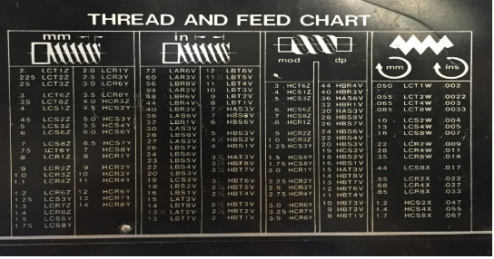
Figure 1. Thread and Feed Chart
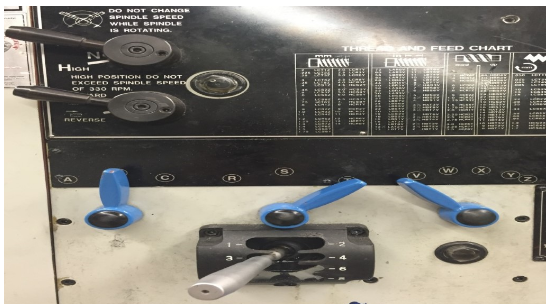
Figure 2. Setting Gearbox
3. Set the compound rest at 29 degrees to the right for right hand threads.
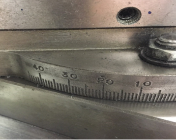
Figure 3. 29 Degrees
4. Install a 60 degree threading tool bit and set the height to the lathe center point.
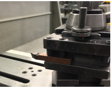
Figure 4. 60 Degree Threading Tool
5. Set the tool bit and a right angles to the work, using a thread gage.
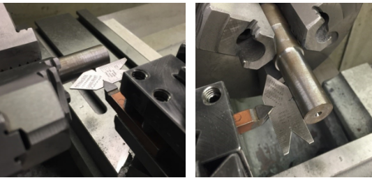
Figure 5. Using the Center gage to positionthe tool for machining Threads
6. Using a layout solution, coat the area to be threaded.
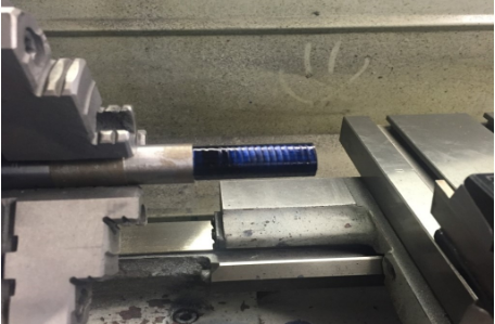
Figure 6. Layout
7. Move the threading tool up to the part using both the compound and the cross feed. Set the micrometer to zero on both dials.
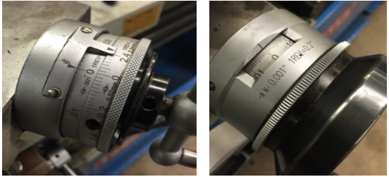
Figure 7. Compound Figure 8. Cross Feed
8. Move cross feed to the back tool off the work, move carriage to the end of the part and reset the cross feed to zero.
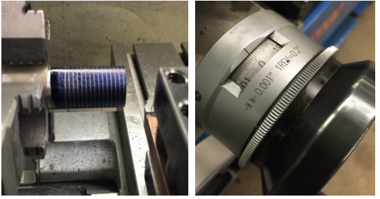
Figure 9. End of the part and Cross feed to Zero
9. Using only the compound micrometer, feed in .001 to .002 inch.
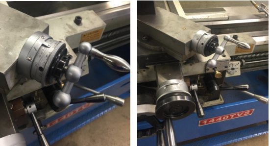
Figure 10: Compound feed in .002 inch
10. Turn on the lathe and engage the half nut.
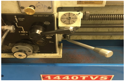
Figure 11 : On/Off Lever and Half Nut
11. Take a scratch cut on the part without cutting fluid. Disengage the half nut at the end of the cut, stop the lathe and back out the tool using the cross feed. Return the carriage to the starting position.
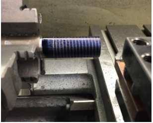
Figure 12. Starting Position
12. Using a screw pitch gage or a rule check the thread pitch. (Threads per inch)
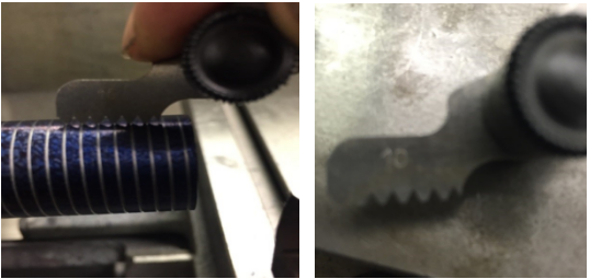
Figure 13. Screw Pitch Gage Figure 14. Screw Pitch Gage(10)
13. Feed the compound in .005 to .020 inch for the first pass using cutting oil. As you get near the final size, reduce the depth of cut to .001 to .002 inch.
14. Continue this process until the tool is within .010 inch of the finish depth.
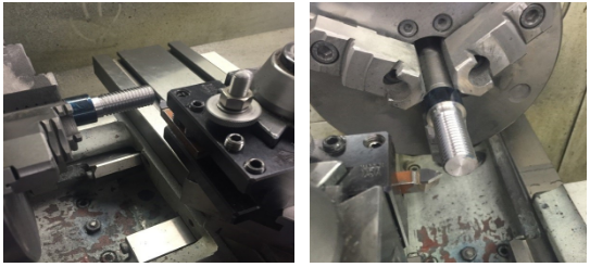
Figure 15. Threading operation
15. Check the size using a screw thread micrometer, thread gage, or using the three wire system.

Figure 16. Three wire measurement
16. Chamfer the end of the thread to protect it from damage.
Reaming
Reamers are used to finish drilled holes or bores quickly and accurately to a specified sized hole and to produce a good surface finish. Reaming may be performed after a hole has been drilled or bored to within 0.005 to 0.015 inch of the finished size since the reamer is not designed to remove much material.
The workpiece is mounted in a chuck at the headstock spindle and the reamer is supported by the tailstock.
The lathe speed for machine reaming should be approximately 1/2 that used for drilling.
Reaming with a Hand Reamer
The hole to be reamed by hand must be within 0.005 inch of the required finished size.
The workpiece is mounted to the headstock spindle in a chuck and the headstock spindle is locked after the workpiece is accurately setup. The hand reamer is mounted in an adjustable reamer wrench and supported with the tailstock center. As the wrench is revolved by hand, the hand reamer is fed into the hole simultaneously by turning the tailstock handwheel. Use plenty cutting fluid for reaming.
Reaming with a Machine Reamer
The hole to be reamed with a machine reamer must be drilled or bored to within 0.010 inch of the finished size so that the machine reamer will only have to remove the cutter bit marks. Use plenty cutting fluid for reaming.
Grind a Lathe Tool bit
Procedure:
1. Grip the tool bit firmly while supporting the hand on the grinder tool set.
2. Hold the tool bit at the proper angle to grind the cutting edge angle. At the same, tilt the bottom of the tool bit in towards the wheel and grind 10 degrees side relief or clearance angle on the cutting edge. The cutting edge should be about .5 inches long and should be over about ¼ the width of the tool bit.
3. While grinding tool bit, move the tool bit back and forth across the face of the grinding wheel. This accelerates grinding and prevents grooving the wheel.
4. The tool bit must be cooled frequently during the grinding operation by dip into the water. Never overheat a tool bit.
5. Grind the end cutting angle so that it form an angle a little less than 90 degrees with the side cutting edge. Hold the tool so that the end cutting edge angle and end end relief angle of 15 degrees are ground at the same time.
6. Check the amount of end relief when the tool bit is in the tool holder.
7. Hold the top of the tool bit at about 45 degrees to the axis of the wheel and grind the side rake about 14 degrees.
8. Grind a slight radius on the point of the cutting tool, being sure to maintain the same front and side clearance angle.
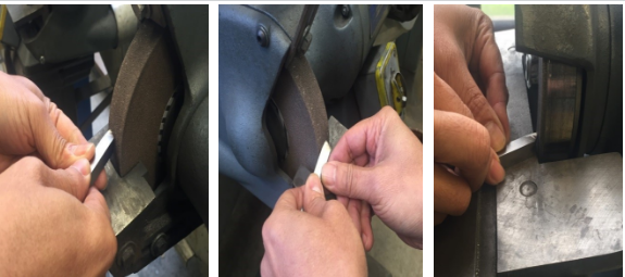
Grind front Grind side Grind radius
Cutting tool Materials
Lathe tool bits are generally made of four materials:
1. High speed steel
2. Cast alloys
3. Cemented Carbides
4. Ceramics
The properties that each of these materials possess are different and the application of each depends on the material being machined and the condition of the machine.
Lathe tool bits should possess the following properties.
1. They should be hard.
2. They should be wear resistant.
3. They should be capable of standing up to high temperatures developed during the cutting operation.
4. They should be able to withstand shock during the cutting operation.
Cutting tool Nomenclature
Cutting tools used on a lathe are generally single pointed cutting tools and although the shape of the tool is changed for various applications. The same nomenclature applies to all cutting tools.
Procedure:
1. Base: the bottom surface of the tool shank.
2. Cutting Edge: the leading edge of the tool bit that does the cutting.
3. Face: the surface against which the chip bears as it is separated from the work.
4. Flank: The surface of the tool which is adjacent to and below the cutting edge.
5. Nose: the tip of the cutting tool formed by the junction of the cutting edge and the front face.
6. Nose radius: The radius to which the nose is ground. The size of the radius will affect the finish. For rough cut, a 1/16 inch nose radius used. For finish cut, a 1/16 to ⅛ inch nose radius is used.
7. Point: The end of the tool that has been ground for cutting purposes.
8. Shank: the body of the tool bit or the part held in the tool holder.
9. Lathe Tool bit Angles and Clearances
Proper performance of a tool bit depends on the clearance and rake angles which must be ground on the tool bit. Although these angles vary for different materials, the nomenclature is the same for all tool bits.
• Side cutting edge angle: The angle which the cutting edge forms with the side of the tool shank. This angle may be from 10 to 20 degrees depending on the material being cut. If angle is over 30 degrees, the tool will tend to chatter.
• End cutting edge angle. The angle formed by the end cutting edge and a line at right angle to the centerline of the tool bit. This angle may be from 5 to 30 degrees depending on the type of cut and finish desired. For roughing cuts an angle of 5 to 15 degrees, angle between 15 and 30 degrees are used for general purpose turning tools. The larger angle permits the cutting tool to be swivelled to the left when taking light cuts close to the dog or chuck, or when turning to a shoulder.
• Side Relief (clearance) angle: The angle ground on the flank of the tool below the cutting edge. This angle may be from 6 to 10 degrees. The side clearance on a tool bit permit the cutting tool to advance lengthwise into the rotating work and prevent the flank from rubbing against the workpiece.
• End Relief (clearance) angle: the angle ground below the nose of the tool bit which permits the cutting tool to be fed into the work. This angle may be 10 to 15 degrees for general purpose cut. This angle must be measured when the tool bit is held in the tool holder. The end relief angle varies with the hardness and type of material and type of cut being taken. The end relief angle is smaller for harder materials, to provide support under the cutting edge.
• Side Rake Angle: The angle at which the face is ground away from the cutting edge. This angle may be 14 degrees for general purpose tool bits. Side rake centers a keener cutting edge and allows the chip to flow away quickly. For softer materials, the side rake angle is generally increased.
• Back (Top) Rake: The backward slope of the tool face away from the nose. This angle may be about 20 degrees and is provide for in the tool holder. Back rake permits the chips to flow away from the point of the cutting tool.
UNIT TEST
1. What is pitch for ¼-20 tap?
2. To what angle must the compound be turned for Unified Thread?
3. Explain why you swivel the compound in Question 2.
4. What is the depth of thread for UNF ½-20 screw?
5. How would you make a left-hand thread? This is not covered in the reading—think it out?
6. What Tool bit do we use for cutting thread?
7. Please describe Center Gage.
8. What do we use to check the thread pitch(Thread Per Inch)?
9. The first and final pass, how much do we feed the compound in?
10. Name four material that use to make Tool bits.
Chapter Attribution Information
This chapter was derived from the following sources.
- Lathe derived from Lathe by the Massachusetts Institute of Technology, CC:BY-NC-SA 4.0.
- Cutting Tool Terminology derived from Lathe Cutting Tools – Cutting Tool Shapes by the Wisconsin Technical College, CC:BY-NC 4.0.
- Cutting Tool Terminology derived from Cutter Types (Lathe) by the University of Idaho, CC:BY-SA 3.0.
- Centering derived from [Manual Lathes Document]