
3: Chapter 3. Create dimensions and components
- Page ID
- 13179

\( \newcommand{\vecs}[1]{\overset { \scriptstyle \rightharpoonup} {\mathbf{#1}} } \)
\( \newcommand{\vecd}[1]{\overset{-\!-\!\rightharpoonup}{\vphantom{a}\smash {#1}}} \)
\( \newcommand{\id}{\mathrm{id}}\) \( \newcommand{\Span}{\mathrm{span}}\)
( \newcommand{\kernel}{\mathrm{null}\,}\) \( \newcommand{\range}{\mathrm{range}\,}\)
\( \newcommand{\RealPart}{\mathrm{Re}}\) \( \newcommand{\ImaginaryPart}{\mathrm{Im}}\)
\( \newcommand{\Argument}{\mathrm{Arg}}\) \( \newcommand{\norm}[1]{\| #1 \|}\)
\( \newcommand{\inner}[2]{\langle #1, #2 \rangle}\)
\( \newcommand{\Span}{\mathrm{span}}\)
\( \newcommand{\id}{\mathrm{id}}\)
\( \newcommand{\Span}{\mathrm{span}}\)
\( \newcommand{\kernel}{\mathrm{null}\,}\)
\( \newcommand{\range}{\mathrm{range}\,}\)
\( \newcommand{\RealPart}{\mathrm{Re}}\)
\( \newcommand{\ImaginaryPart}{\mathrm{Im}}\)
\( \newcommand{\Argument}{\mathrm{Arg}}\)
\( \newcommand{\norm}[1]{\| #1 \|}\)
\( \newcommand{\inner}[2]{\langle #1, #2 \rangle}\)
\( \newcommand{\Span}{\mathrm{span}}\) \( \newcommand{\AA}{\unicode[.8,0]{x212B}}\)
\( \newcommand{\vectorA}[1]{\vec{#1}} % arrow\)
\( \newcommand{\vectorAt}[1]{\vec{\text{#1}}} % arrow\)
\( \newcommand{\vectorB}[1]{\overset { \scriptstyle \rightharpoonup} {\mathbf{#1}} } \)
\( \newcommand{\vectorC}[1]{\textbf{#1}} \)
\( \newcommand{\vectorD}[1]{\overrightarrow{#1}} \)
\( \newcommand{\vectorDt}[1]{\overrightarrow{\text{#1}}} \)
\( \newcommand{\vectE}[1]{\overset{-\!-\!\rightharpoonup}{\vphantom{a}\smash{\mathbf {#1}}}} \)
\( \newcommand{\vecs}[1]{\overset { \scriptstyle \rightharpoonup} {\mathbf{#1}} } \)
\( \newcommand{\vecd}[1]{\overset{-\!-\!\rightharpoonup}{\vphantom{a}\smash {#1}}} \)
\(\newcommand{\avec}{\mathbf a}\) \(\newcommand{\bvec}{\mathbf b}\) \(\newcommand{\cvec}{\mathbf c}\) \(\newcommand{\dvec}{\mathbf d}\) \(\newcommand{\dtil}{\widetilde{\mathbf d}}\) \(\newcommand{\evec}{\mathbf e}\) \(\newcommand{\fvec}{\mathbf f}\) \(\newcommand{\nvec}{\mathbf n}\) \(\newcommand{\pvec}{\mathbf p}\) \(\newcommand{\qvec}{\mathbf q}\) \(\newcommand{\svec}{\mathbf s}\) \(\newcommand{\tvec}{\mathbf t}\) \(\newcommand{\uvec}{\mathbf u}\) \(\newcommand{\vvec}{\mathbf v}\) \(\newcommand{\wvec}{\mathbf w}\) \(\newcommand{\xvec}{\mathbf x}\) \(\newcommand{\yvec}{\mathbf y}\) \(\newcommand{\zvec}{\mathbf z}\) \(\newcommand{\rvec}{\mathbf r}\) \(\newcommand{\mvec}{\mathbf m}\) \(\newcommand{\zerovec}{\mathbf 0}\) \(\newcommand{\onevec}{\mathbf 1}\) \(\newcommand{\real}{\mathbb R}\) \(\newcommand{\twovec}[2]{\left[\begin{array}{r}#1 \\ #2 \end{array}\right]}\) \(\newcommand{\ctwovec}[2]{\left[\begin{array}{c}#1 \\ #2 \end{array}\right]}\) \(\newcommand{\threevec}[3]{\left[\begin{array}{r}#1 \\ #2 \\ #3 \end{array}\right]}\) \(\newcommand{\cthreevec}[3]{\left[\begin{array}{c}#1 \\ #2 \\ #3 \end{array}\right]}\) \(\newcommand{\fourvec}[4]{\left[\begin{array}{r}#1 \\ #2 \\ #3 \\ #4 \end{array}\right]}\) \(\newcommand{\cfourvec}[4]{\left[\begin{array}{c}#1 \\ #2 \\ #3 \\ #4 \end{array}\right]}\) \(\newcommand{\fivevec}[5]{\left[\begin{array}{r}#1 \\ #2 \\ #3 \\ #4 \\ #5 \\ \end{array}\right]}\) \(\newcommand{\cfivevec}[5]{\left[\begin{array}{c}#1 \\ #2 \\ #3 \\ #4 \\ #5 \\ \end{array}\right]}\) \(\newcommand{\mattwo}[4]{\left[\begin{array}{rr}#1 \amp #2 \\ #3 \amp #4 \\ \end{array}\right]}\) \(\newcommand{\laspan}[1]{\text{Span}\{#1\}}\) \(\newcommand{\bcal}{\cal B}\) \(\newcommand{\ccal}{\cal C}\) \(\newcommand{\scal}{\cal S}\) \(\newcommand{\wcal}{\cal W}\) \(\newcommand{\ecal}{\cal E}\) \(\newcommand{\coords}[2]{\left\{#1\right\}_{#2}}\) \(\newcommand{\gray}[1]{\color{gray}{#1}}\) \(\newcommand{\lgray}[1]{\color{lightgray}{#1}}\) \(\newcommand{\rank}{\operatorname{rank}}\) \(\newcommand{\row}{\text{Row}}\) \(\newcommand{\col}{\text{Col}}\) \(\renewcommand{\row}{\text{Row}}\) \(\newcommand{\nul}{\text{Nul}}\) \(\newcommand{\var}{\text{Var}}\) \(\newcommand{\corr}{\text{corr}}\) \(\newcommand{\len}[1]{\left|#1\right|}\) \(\newcommand{\bbar}{\overline{\bvec}}\) \(\newcommand{\bhat}{\widehat{\bvec}}\) \(\newcommand{\bperp}{\bvec^\perp}\) \(\newcommand{\xhat}{\widehat{\xvec}}\) \(\newcommand{\vhat}{\widehat{\vvec}}\) \(\newcommand{\uhat}{\widehat{\uvec}}\) \(\newcommand{\what}{\widehat{\wvec}}\) \(\newcommand{\Sighat}{\widehat{\Sigma}}\) \(\newcommand{\lt}{<}\) \(\newcommand{\gt}{>}\) \(\newcommand{\amp}{&}\) \(\definecolor{fillinmathshade}{gray}{0.9}\) Session Objectives
Upon completing this session, students will be able to:
(CO 1) Add/Edit dimensions (in model space) – Dim, & Dimension style
(CO 2) Add/Edit blocks from AutoCAD Tool Palette & Other sources – Door, Window, Column, Plumbing, Furniture & Equipment
(CO 3) Create custom blocks – Custom furniture
 Session Highlights
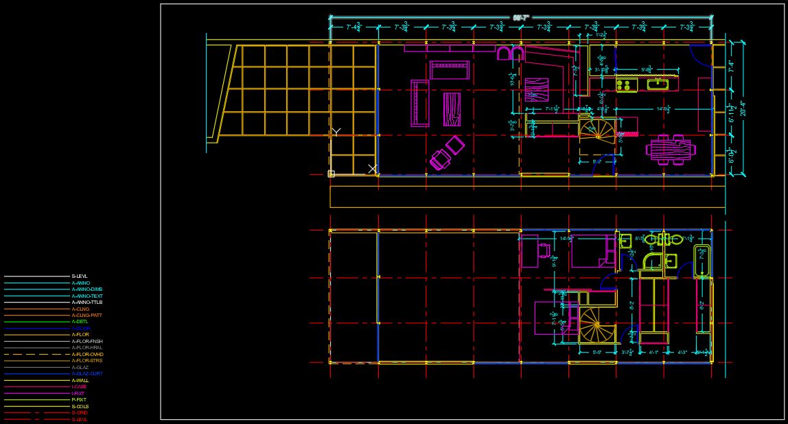
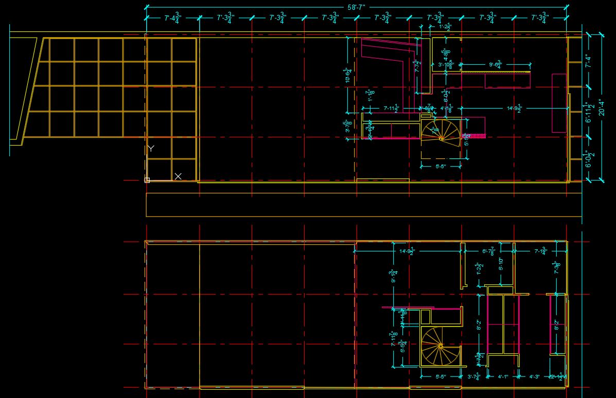
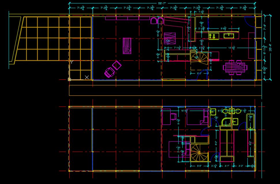
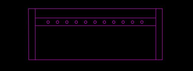
At the end of the session, students can create the graphics below.
 Lecture Contents
(CO 1) Add/Edit dimensions (in model space) – Dim, & Dimension style
- Dim, & Dimension style")
A YouTube element has been excluded from this version of the text. You can view it online here: https://iastate.pressbooks.pub/visualgraphiccomm/?p=78
Open your working CAD file.
Understand CAD dimension scale settings
- [METHOD 01] Dimension in model space for plotting in model space – This is the traditional method used with single-view drawings – Need Text height charts for correct text height, and it is challenging to be flexible in drawing scale.
- [METHOD 02] Dimension in model space for printing or plotting in paper space – This was the preferred method for complex, multiple-view drawings. (We will practice this method for our project)
- [METHOD 03] dimension in layouts – This is the simplest dimensioning method
- Please refer to this link for more information about scale for dimensions
Text Heights in paper space (1=1)
- 10 pt = 3/32” (minimum font to read)
- 12 pt = 1/8” (Standard text size)
- 18 pt = 3/16” (Subtitle text size)
- 24 pt = 1/4” (Title text size)
Understand the types of dimensions
- The basic types of dimensioning are linear, radial, angular, ordinate, and arc length.
- Please refer to this link for more information about the types of dimensions
Before you add dimensions, move the inserted drawing image to avoid accidental deletes and confusion.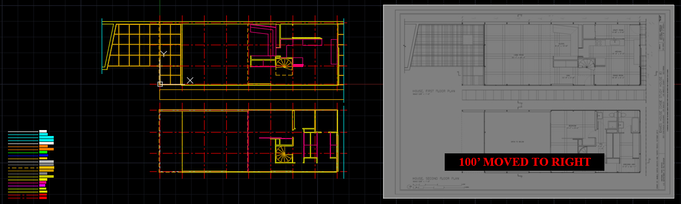
Move the image to the right side – 100ft or any number that you can easily remember. You might need to move the image back to the original position.
Note. Make sure you turn on [ortho]
Set Drawing scale
- Before you start to add dimensions, it is recommended to set the drawing scale. Sometimes, the drawing scale can be changed for the drawing. However, once you set the drawing scale, less work is needed at the end.
- The drawing scale is defined with some factors – the paper size, purposes of submissions, and so on.
- For this project, you will be asked to print out your drawings in 11in x 17in (Horizontal layout). Although the inserted original drawing scale is 3/8″ = 1′ -0″, your drawing scale should be 3/16″ = 1′ -0″
- To set the scale, click the drawing scale [1:1] and select the drawing scale [3/16″ = 1′ -0″]
image credit: Screen captured and modified by the Author from the application
- If you cannot find the ft-in types of scale, click [Custom] > click [Add] > add the name of the scale [3/16” = 1’-0”], add the value on Paper units [3/16], add the value on Drawing units [12] > click [OK] to complete the custom scale > click [OK] to set the scale
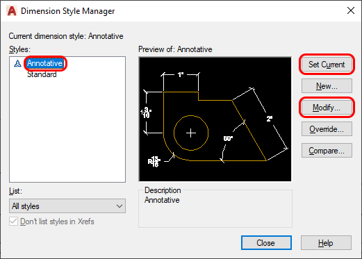
Set Dimension style
“A dimension style is a named collection of dimension settings that control the appearance of dimensions, such as arrowhead style, text location, and lateral tolerances.” (Autodesk help, Mar 29, 2020)
Please refer to this link for more information about dimension style
- [STEP 01] To open Dimension Style Manager,
click [Annotation] ribbon tab, click [ ] on Dimension panel
or, type [ddim] and press [Enter] key - [STEP 02] Click [Annotative] > Click [Set Current] > Click [Modify] to open Modify Dimension Style: Annotative window
- [STEP 03] Click [Lines] tab
adjust the Baseline Spacing to 1/16″
adjust the Extend beyond dim lines to 1/16″
adjust the Offset from origin to 1/16″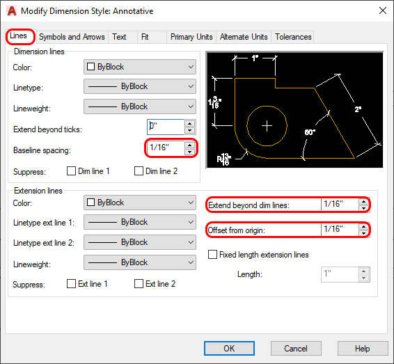
- [STEP 04] Click [Symbols and Arrows] tab
adjust the first Arrowheads to / Architectural tick
adjust the second Arrowheads to / Architectural tick
adjust the arrow size to 1/8″
adjust the break size to 1/16″
adjust the Jog height factor to 1/16″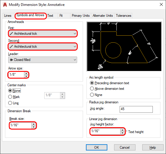
- [STEP 05] Click [Text] tab
adjust the text height to 1/8″
select Aligned with the dimension line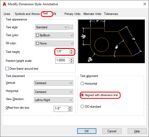
- [STEP 06] Click [Fit] tab
make sure [Annotative] is checked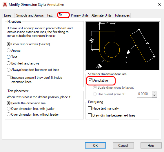
- [STEP 07] Click [Primary Units]
adjust the Unit format to Architectural
adjust the Precision to 0′ -0 1/8″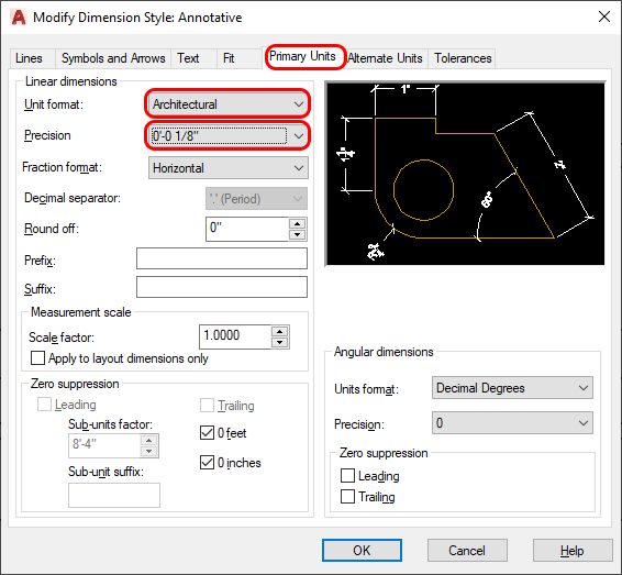
- [STEP 08] Click [OK] to complete the modification > Click [Close] to finish the dimension style manager
Add dimensions
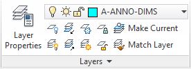
- [STEP 01] Change layer to [A-ANNO-DIMS]
- [STEP 02] Click [Annotate] ribbon tab > make sure the dimension style is [Annotative] > click [Linear] to draw dimensions
or, type [dim] and press [Enter]
If Linear doesn’t fit for your purpose, please select the types of dimension that you want to add.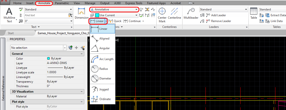
- [STEP 03] make sure you turn on Object Snap
Click the intersection point at the top left corner of the building column grids
Click the next intersection point for dimensioning
Click a third time to place the dimension line and text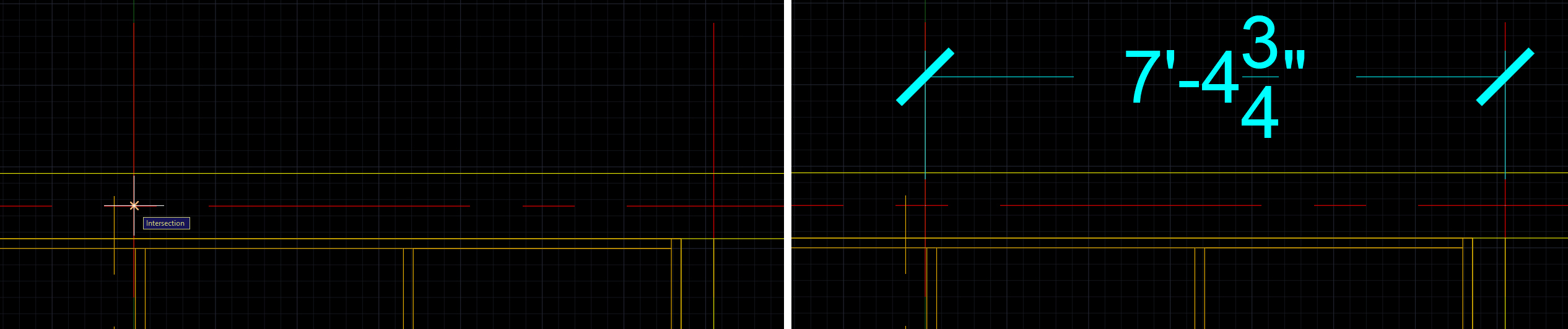
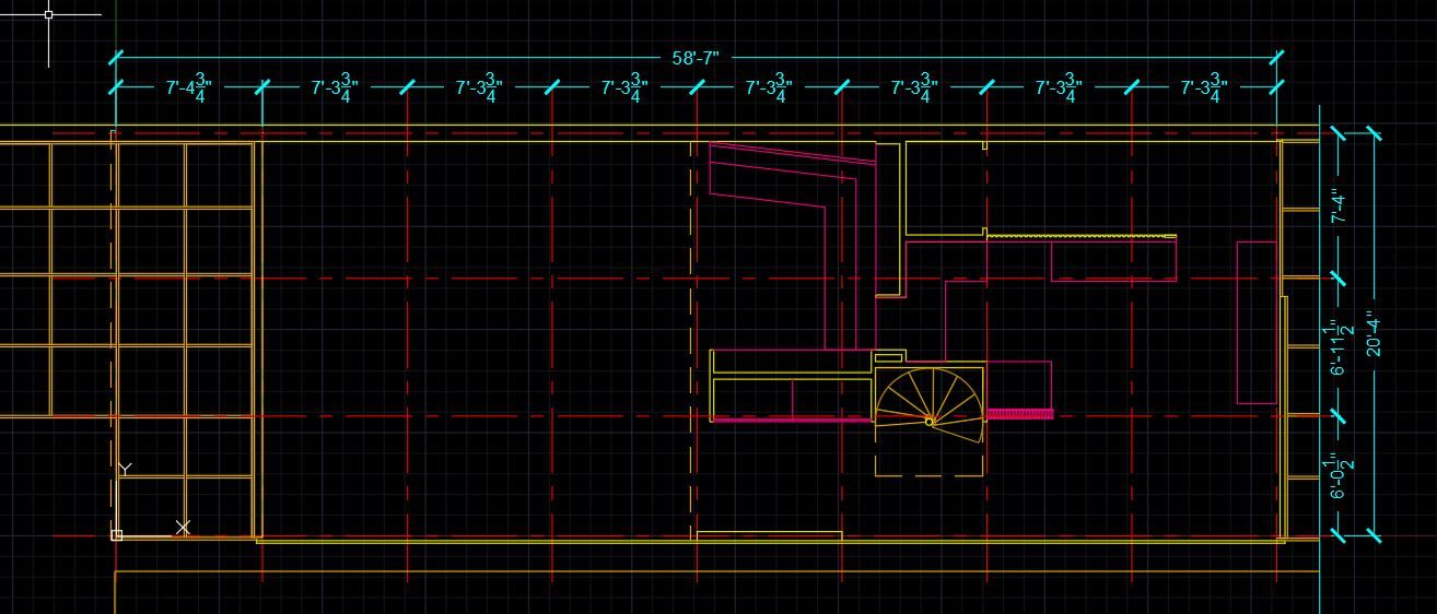
- [STEP 04] if the dimensions are in a continuous string, please use [continue]
 from the [Annotation] tab, [Dimensions] panel.
Add additional dimension lines to the previous dimension. - [STEP 05] Repeat to dimension all column grids for the first floor and overall building dimensions.
Add a new dimension style
– 3/32″ text size – Annotative and interior wall dimensions.
- [STEP 01] Type [ddim], and press [Enter] key to open [Dimension Style Manager]
- [STEP 02] Click [New] to create a new dimension style
- [STEP 03] Add new style name [Annotative 3-32], check start with [Annotative], [Annotative] checked, and click [Continue]
- [STEP 04] Adjust Arrow size from Symbols and Arrows to 1/8″,
adjust Text height from Text to 3/32″
click [OK], click [Set Current] and click [Close] - [STEP 05] Make sure your layer is correct in [A-ANNO-DIMS]
- [STEP 06] Type [dim], and press [Enter] key and start dimensioning for the interior walls (You don’t need to match your dimensions exactly, as reference for this project, +/- 4 inches are acceptable)
(CO 2) Add/Edit blocks from AutoCAD Tool Palette & Other sources – Door, Window, Column, Plumbing, Furniture & Equipment

A YouTube element has been excluded from this version of the text. You can view it online here: https://iastate.pressbooks.pub/visualgraphiccomm/?p=78
Understanding the concept of blocks in AutoCAD
- A block is a collection of objects that are combined into a single named object.
- Although a block and a group in AutoCAD look similar, these are different concepts.
Basically, blocks are copies that will change if you change one, but groups will not change. Groups are unique. - A block consists of the name of the block, the block geometry, the location of the base point, and any associated attribute data.
- For more information about blocks, please refer to this page
Source of blocks
Designers/drafters often bring blocks from outside resources. They use free resources from other websites and/or resources from the firm for schematic design to save time, resources from manufacturers for design development, and/or construction documents.
AutoCAD provides some basic blocks. You can find the block from the [Content Browser] and add blocks to [Tool Palette] and [Design Center]
Cad library websites
- BIM object – https://www.bimobject.com/en-us
- CAD blocks – https://cad-blocks.net/index.html
- DWG models – https://dwgmodels.com/interiors/
Furniture manufactures websites for the Cad library
- Knoll – https://www.knoll.com/design-plan/resources/furniture-symbols
- HermanMiller – https://www.hermanmiller.com/resources/3d-models-and-planning-tools/product-models/
- Steelcase – https://www.steelcase.com/resources/3d-models-cad/
- AllSteel – https://cms.allsteeloffice.com/Pages/Design-Resources/Planning-Tools/PlanningToolsLandingPage.aspx
If designers/drafters cannot find blocks that they want to use for the project, they can create custom blocks. Sometimes it saves more time.
Add blocks from Tool Palettes (Use basic blocks from AutoCAD library)
Move the linked Eames House Floor plan image to match the drawing for reference– We moved the image to 100ft to the right. At this time, move the image back to the original place. If the image is hidden, show the image by clicking [Show Image] on the Image ribbon. If the image hides your drawing (Cad objects), let’s change the drawing order by mouse right-click on the image and click [Draw Order] > click [Send to Back]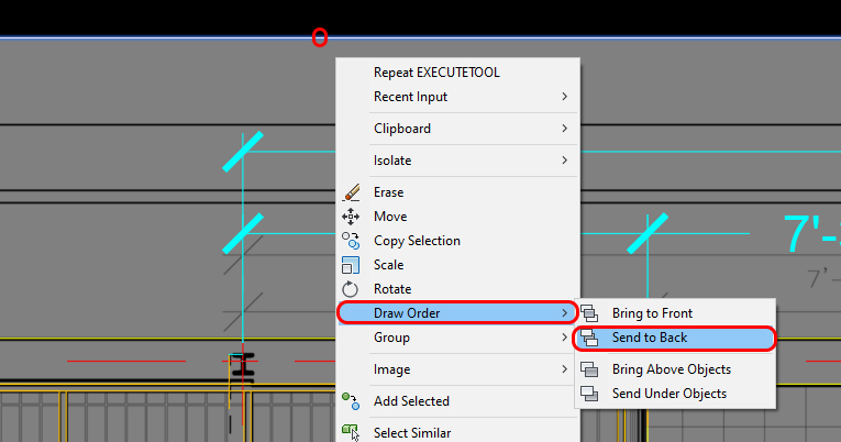
We will add columns from the tool palettes.
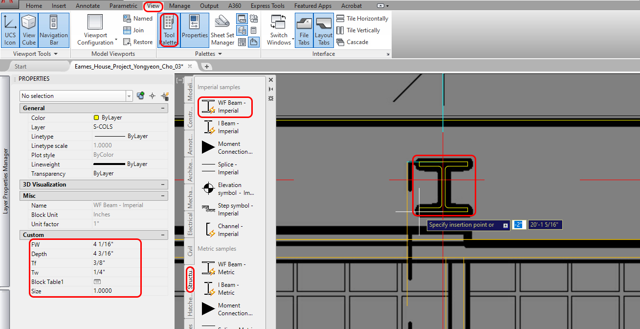
- [STEP 01] Click [View] tab > Click [Tool Palettes] under Palettes panel to open the panel or, type [TOOLPALETTES] on the command, and press [Enter] key
Once the tool palettes are open, place the palette in a comfortable location (I personally like all palettes on the left side of the application. - [STEP 02] Click [Structure] tab on the tool palettes > Click [WF beam – Imperial]
- [STEP 03] Change the layer to [S-COLS]
- [STEP 04] Place the column on the top-left corner of the building. At this time, you cannot place the [WF beam – imperial] to the precise location.
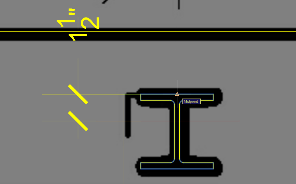
- [STEP 05] Move the column to the right position using [osnap] and guidelines
- [STEP 06] Copy the column to other positions of the first-floor plan; you will need to rotate the drawing and adjust your drawing according to the column locations.
Tips. Use the intersection with object snap [F3] and ortho tool [F8]
- [STEP 07] Copy the columns on the first floor to the second floor.
You may lock the layers that do not need to be selected. After you copy the columns on the first floor to the second floor, you may also unlock the layer you locked.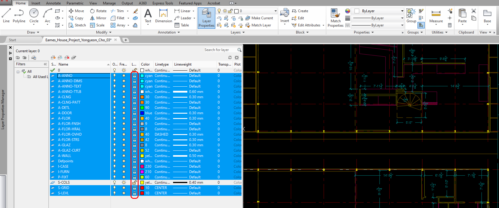
Edit a Dynamic block
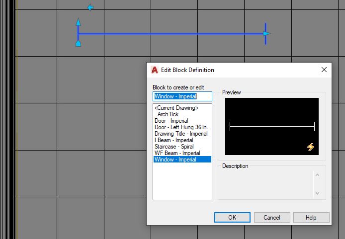
You can find [Door-Imperial] and [Window-Imperial] from the Architecture tab on the tool palettes to add to your drawing. However, the currently loaded blocks (ex. [Door-Imperial] and [Window-Imperial] with a thunderbolt image) on the tool palettes are called [Dynamic block], a dynamic block is a parametric block that users can easily modify.
- [STEP 01] Click [Window – imperial] on the tool palette
- [STEP 02] Place [Window – imperial] block in your drawing
- [STEP 03] Double-click [Window – imperial] to open Edit Block Definition
- [STEP 04] Click [OK] to open the Block Editor
- [STEP 05] Select [Width=3’-0”] and adjust [Dist type] to [Increment] on the properties palette. And adjust [Dist increment] to [1/4”]

- [STEP 06] Select [Wall=0’-4”] and adjust [Dist type] to [Increment] on the properties palette
- [STEP 07] Click [Save Block] from the [Block Editor] ribbon
- [STEP 08] Click [Close Block Editor] to close
- [STEP 09] Relocate the window and update the size of the window according to the floor plan
Repeat the steps for [Door-Imperial]. You will need to change the [Dist type] for [Door Size] and [Wall Thickness]
Complete placing and adjusting windows (curtain walls) and door (interior and exterior doors) within correct layers. If you can find the blocks, you can draw the elements with [line] or [poly line]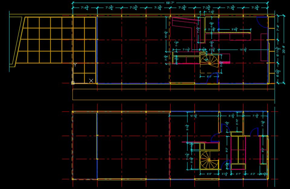
Add more blocks using [Design Center]
Design Center is a tool to access and add blocks, Dimension styles, Layers, Layouts, Line types, Multi leaders, Table styles, Visual styles, and Xrefs.
For more information about the Design Center, please refer to this page
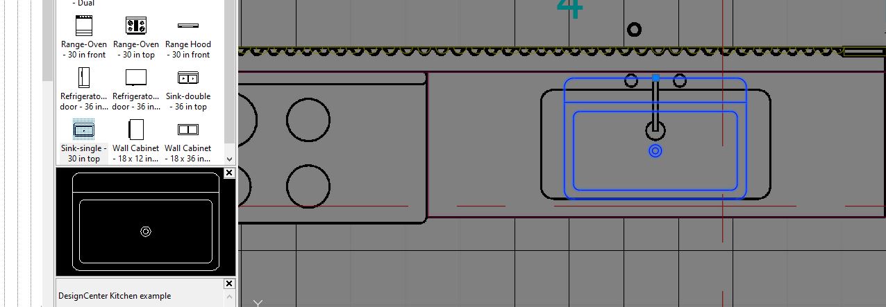
I am going to demonstrate how to load a sink from the AutoCAD sample blocks.
- [STEP 01] Change layer to [P-FIXT]
- [STEP 02] Click [View] tab > Click [Design Center] icon

or, Type [adcenter] on the command line, and press [Enter] key to open the Design Center window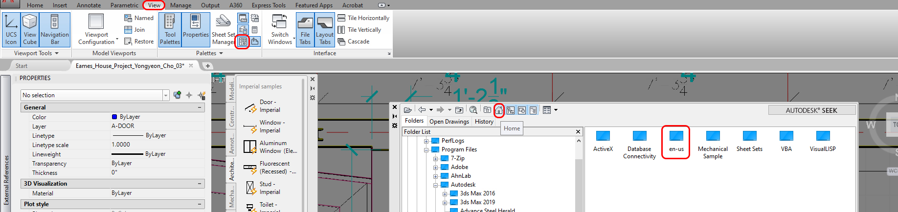
- [STEP 03] Once you click the [Home] icon
 , you can find [en-us] folder > double-click to open [en-us] > double-click to open [Design Center]. You can find some sample drawings containing blocks
The folder structure may be different from the versions of AutoCAD, but generally, you can find the sample CAD files
C:\Program Files\Autodesk\AutoCAD 2020\Sample\en-us\DesignCenter - [STEP 04] Double-click [Kitchens.dwg] > Double-click [Blocks] > Double-click [Sink-single-30 in top] to inset in your file > Click [OK] to confirm the information
- [STEP 05] Place the sink in the kitchen, using object snap
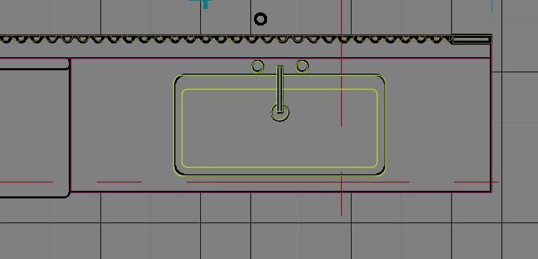
- [STEP 6] Click the inserted block [Sink-single-30 in top] > Mouse right-click > Click [Edit Block In-place] > Click [OK] on reference Edit
- [STEP 7] Use [Stretch] tool to resize the sink, and delete elements that are not needed, and add geometrics for the sink
Note 1. For the assignment, you don’t need to make the model 100% the same. Some flexibility will be acceptable (shape of sink and faucet)
Note 2. When you draw a new line and element, use the [0] layer in a block - [STEP 8] Once you are done with the editing > Click [Save Changes] on the [Home] ribbon, under [Edit Reference] panel
If you want to rename the block, type [rename] on the commend. > Click [blocks] > Click [blocks that you want to rename]
If the block is your own or whether it was modified from another or created new, add [000_] in the first part of the block name to recognize/find the block easily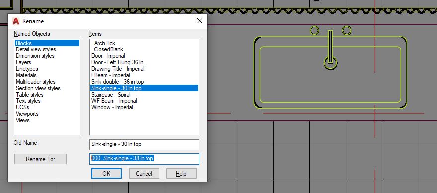
If you want to use a downloaded CAD file (e.g., https://cad-blocks.net/kitchen-cad-blocks-kitchen-sink.html ).
- Save the downloaded file in a project folder
- Open the [design center]
- Click [Load]
- Find the project folder where you saved the downloaded cad file
- Click [Open] to load
- Double-click [Blocks]
- Select a block that you want to use in your project and double click to load
If the inserted block is the wrong scale, adjust the scale.
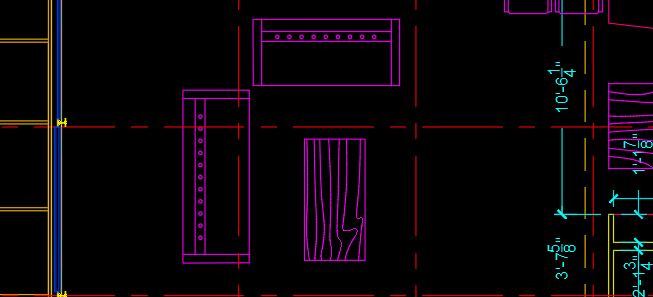
Please use these strategies to draw plumbing fixtures in the kitchen and bathrooms.
You will select your selections of blocks. The below image is a reference only.
- Add (2) beds in the bedrooms
- Add (1) desk and chair set in the bedroom
- Add (1) dining table-chair set in the dining area
- Add (1) table in the alcove
- Add (1) table in the living room
- Add bookshelves in the living room
- Add (1) lounge chair in the living room
- Add (2) chairs in the living room
We will ask you to create custom furniture (sofa set) below.
(CO 3) Create custom blocks – Custom furniture

A YouTube element has been excluded from this version of the text. You can view it online here: https://iastate.pressbooks.pub/visualgraphiccomm/?p=78
Sometimes, you may experience difficulty finding CAD blocks from CAD library websites and/or manufacturers’ websites. Especially, it is hard to find furniture blocks for residential projects. In this tutorial, you will learn how to create blocks using product information and photos. I will demonstrate it using two different sofa sizes from the website Design Within Reach (DWR). You will create using your selections of furniture for the project.
Create an 86″ sofa block
- [STEP 01] Retrieve the product information (dimensions) and images from the DWR website
- [STEP 02] Change layer to [0] > Draw overall size of the sofa (Width=86” & Depth=33”) using [pline] or [rectang], make sure turn [ortho] on for 90 degree
- [STEP 03] Download or screenshot the product image to your project folder
Most of the time, you cannot find a top view of a product. You may rely on a front view to draw a floor plan view for the product. - [STEP 04] Insert the front view image into your drawing file. Click [Insert] tab > Click [Attach] > Click the downloaded file > Click [Open] > Click [OK] on Attach Image > Click once on the drawing area > Click once again near the first point > Click the inserted image > Adjust the [Fade] value to [50] > mouse right-click on the image > Click [Drawing Order] > Click [Send to back]
- [STEP 05] Relocate and rescale the inserted image to match the overall sofa dimensions.
For relocating, you will need to use [Move], [Rotate], and [osnap] command.
For rescaling, you will need to use [scale] with Reference [R]. - [STEP 06] Draw the details of the sofa using [line], [pline], [rectang], and [circle]. Use the detailed dimensions what the website provided. Also verify the dimensions using [distance] – type [di] and press [Enter] key
- [STEP 07] Before defining the lines to a block, make sure all lines are in the [0] layer.
- [STEP 08] Select all lines for the sofa (excluding the inserted image) > Type [b] on the command line and press [Enter]. Block Definition window will open > Name the block something meaningful (e.g., 000_DWR-Bantam_Sofa-Plan) > Click [OK] > Change the block from [0] layer to [I-FURN] > If you don’t need the inserted image anymore, you can delete the image.
Create a 73″ sofa block using the [000_DWR-Bantam_Sofa-Plan] block
Rather than redraw the 73″ sofa block from scratch, you can start with the [000_DWR-Bantam_Sofa-Plan] block and using the Stretch tool to adjust the length.
- [STEP 01] Type [co] to copy [000_DWR-Bantam_Sofa-Plan] block or Insert the [000_DWR-Bantam_Sofa-Plan] block on the drawing area – Click [Insert] tab > Click [insert] icon under Block panel > Select the block > place the block on the drawing area.
- [STEP 02] Type [x], and press [Enter] key. The Explode command breaks up a block into individual lines. This commend is useful to convert a block into elements for redefining a block.
For more information about this command, refer to this page. - [STEP 03] Use [Stretch] commend to resize the sofa. And edit the details.
- [STEP 04] Create a new block by typing [b], and pressing [Enter] > name the block [000_DWR-Bantam_Sofa-73-Front] > update the layer to [I-FURN] > place the sofa
SAVE the file before closing the application.
Save in a different location for the backup (e.g., a cloud folder)
 References
Text and Scale Factors. (n.d.). Retrieved October 19, 2020, from http://cstl-pti.semo.edu/bbowers/files/text%20and%20scale%20factors.pdf
Autodesk.Help. (2018, January 11). About Setting the Scale for Dimensions. Retrieved October 19, 2020, from https://knowledge.autodesk.com/support/autocad/learn-explore/caas/CloudHelp/cloudhelp/2018/ENU/AutoCAD-Core/files/GUID-30D6D9C8-AB99-47D1-B420-3D4EB6C7B0D1-htm.html
Autodesk.Help. (2018, January 11). About the Types of Dimensions. Retrieved October 19, 2020, from https://knowledge.autodesk.com/support/autocad/learn-explore/caas/CloudHelp/cloudhelp/2018/ENU/AutoCAD-Core/files/GUID-9A8AB1F2-4754-444C-B90D-CD3F2FC8A3E0-htm.html
Autodesk.Help. (2020, March 29). About Dimension Styles. Retrieved October 19, 2020, from https://knowledge.autodesk.com/support/autocad/learn-explore/caas/CloudHelp/cloudhelp/2020/ENU/AutoCAD-Core/files/GUID-5469B348-3425-41C6-9CEC-F267BF6CCCA2-htm.html
Autodesk.Help. (2020, March 29). Blocks. Retrieved October 19, 2020, from https://knowledge.autodesk.com/support/autocad/getting-started/caas/CloudHelp/cloudhelp/2019/ENU/AutoCAD-Core/files/GUID-2DA2ADA1-C8CC-4E61-9598-06580FFD3544-htm.html
Autodesk.Help. (2020, March 29). About DesignCenter. Retrieved October 19, 2020, from https://knowledge.autodesk.com/support/autocad/learn-explore/caas/CloudHelp/cloudhelp/2020/ENU/AutoCAD-Core/files/GUID-B3071AE7-76BB-436C-9BAE-CC54CFBD4F96-htm.html
Design Within Reach. (n.d.). Retrieved October 19, 2020, from https://www.dwr.com/living-sofas-sectionals/bantam-sofa/1246.html?lang=en_US#lang=en_US&q=bantam&start=2
Autodesk.Help. (2020, March 29). Explode (Command). Retrieved October 19, 2020, from https://knowledge.autodesk.com/support/autocad/learn-explore/caas/CloudHelp/cloudhelp/2020/ENU/AutoCAD-Core/files/GUID-E98BCEF4-DED6-48A6-87EB-10FE87188083-htm.html