1.3: Module 3- World Coordinate System
- Page ID
- 19937

\( \newcommand{\vecs}[1]{\overset { \scriptstyle \rightharpoonup} {\mathbf{#1}} } \)
\( \newcommand{\vecd}[1]{\overset{-\!-\!\rightharpoonup}{\vphantom{a}\smash {#1}}} \)
\( \newcommand{\dsum}{\displaystyle\sum\limits} \)
\( \newcommand{\dint}{\displaystyle\int\limits} \)
\( \newcommand{\dlim}{\displaystyle\lim\limits} \)
\( \newcommand{\id}{\mathrm{id}}\) \( \newcommand{\Span}{\mathrm{span}}\)
( \newcommand{\kernel}{\mathrm{null}\,}\) \( \newcommand{\range}{\mathrm{range}\,}\)
\( \newcommand{\RealPart}{\mathrm{Re}}\) \( \newcommand{\ImaginaryPart}{\mathrm{Im}}\)
\( \newcommand{\Argument}{\mathrm{Arg}}\) \( \newcommand{\norm}[1]{\| #1 \|}\)
\( \newcommand{\inner}[2]{\langle #1, #2 \rangle}\)
\( \newcommand{\Span}{\mathrm{span}}\)
\( \newcommand{\id}{\mathrm{id}}\)
\( \newcommand{\Span}{\mathrm{span}}\)
\( \newcommand{\kernel}{\mathrm{null}\,}\)
\( \newcommand{\range}{\mathrm{range}\,}\)
\( \newcommand{\RealPart}{\mathrm{Re}}\)
\( \newcommand{\ImaginaryPart}{\mathrm{Im}}\)
\( \newcommand{\Argument}{\mathrm{Arg}}\)
\( \newcommand{\norm}[1]{\| #1 \|}\)
\( \newcommand{\inner}[2]{\langle #1, #2 \rangle}\)
\( \newcommand{\Span}{\mathrm{span}}\) \( \newcommand{\AA}{\unicode[.8,0]{x212B}}\)
\( \newcommand{\vectorA}[1]{\vec{#1}} % arrow\)
\( \newcommand{\vectorAt}[1]{\vec{\text{#1}}} % arrow\)
\( \newcommand{\vectorB}[1]{\overset { \scriptstyle \rightharpoonup} {\mathbf{#1}} } \)
\( \newcommand{\vectorC}[1]{\textbf{#1}} \)
\( \newcommand{\vectorD}[1]{\overrightarrow{#1}} \)
\( \newcommand{\vectorDt}[1]{\overrightarrow{\text{#1}}} \)
\( \newcommand{\vectE}[1]{\overset{-\!-\!\rightharpoonup}{\vphantom{a}\smash{\mathbf {#1}}}} \)
\( \newcommand{\vecs}[1]{\overset { \scriptstyle \rightharpoonup} {\mathbf{#1}} } \)
\(\newcommand{\longvect}{\overrightarrow}\)
\( \newcommand{\vecd}[1]{\overset{-\!-\!\rightharpoonup}{\vphantom{a}\smash {#1}}} \)
\(\newcommand{\avec}{\mathbf a}\) \(\newcommand{\bvec}{\mathbf b}\) \(\newcommand{\cvec}{\mathbf c}\) \(\newcommand{\dvec}{\mathbf d}\) \(\newcommand{\dtil}{\widetilde{\mathbf d}}\) \(\newcommand{\evec}{\mathbf e}\) \(\newcommand{\fvec}{\mathbf f}\) \(\newcommand{\nvec}{\mathbf n}\) \(\newcommand{\pvec}{\mathbf p}\) \(\newcommand{\qvec}{\mathbf q}\) \(\newcommand{\svec}{\mathbf s}\) \(\newcommand{\tvec}{\mathbf t}\) \(\newcommand{\uvec}{\mathbf u}\) \(\newcommand{\vvec}{\mathbf v}\) \(\newcommand{\wvec}{\mathbf w}\) \(\newcommand{\xvec}{\mathbf x}\) \(\newcommand{\yvec}{\mathbf y}\) \(\newcommand{\zvec}{\mathbf z}\) \(\newcommand{\rvec}{\mathbf r}\) \(\newcommand{\mvec}{\mathbf m}\) \(\newcommand{\zerovec}{\mathbf 0}\) \(\newcommand{\onevec}{\mathbf 1}\) \(\newcommand{\real}{\mathbb R}\) \(\newcommand{\twovec}[2]{\left[\begin{array}{r}#1 \\ #2 \end{array}\right]}\) \(\newcommand{\ctwovec}[2]{\left[\begin{array}{c}#1 \\ #2 \end{array}\right]}\) \(\newcommand{\threevec}[3]{\left[\begin{array}{r}#1 \\ #2 \\ #3 \end{array}\right]}\) \(\newcommand{\cthreevec}[3]{\left[\begin{array}{c}#1 \\ #2 \\ #3 \end{array}\right]}\) \(\newcommand{\fourvec}[4]{\left[\begin{array}{r}#1 \\ #2 \\ #3 \\ #4 \end{array}\right]}\) \(\newcommand{\cfourvec}[4]{\left[\begin{array}{c}#1 \\ #2 \\ #3 \\ #4 \end{array}\right]}\) \(\newcommand{\fivevec}[5]{\left[\begin{array}{r}#1 \\ #2 \\ #3 \\ #4 \\ #5 \\ \end{array}\right]}\) \(\newcommand{\cfivevec}[5]{\left[\begin{array}{c}#1 \\ #2 \\ #3 \\ #4 \\ #5 \\ \end{array}\right]}\) \(\newcommand{\mattwo}[4]{\left[\begin{array}{rr}#1 \amp #2 \\ #3 \amp #4 \\ \end{array}\right]}\) \(\newcommand{\laspan}[1]{\text{Span}\{#1\}}\) \(\newcommand{\bcal}{\cal B}\) \(\newcommand{\ccal}{\cal C}\) \(\newcommand{\scal}{\cal S}\) \(\newcommand{\wcal}{\cal W}\) \(\newcommand{\ecal}{\cal E}\) \(\newcommand{\coords}[2]{\left\{#1\right\}_{#2}}\) \(\newcommand{\gray}[1]{\color{gray}{#1}}\) \(\newcommand{\lgray}[1]{\color{lightgray}{#1}}\) \(\newcommand{\rank}{\operatorname{rank}}\) \(\newcommand{\row}{\text{Row}}\) \(\newcommand{\col}{\text{Col}}\) \(\renewcommand{\row}{\text{Row}}\) \(\newcommand{\nul}{\text{Nul}}\) \(\newcommand{\var}{\text{Var}}\) \(\newcommand{\corr}{\text{corr}}\) \(\newcommand{\len}[1]{\left|#1\right|}\) \(\newcommand{\bbar}{\overline{\bvec}}\) \(\newcommand{\bhat}{\widehat{\bvec}}\) \(\newcommand{\bperp}{\bvec^\perp}\) \(\newcommand{\xhat}{\widehat{\xvec}}\) \(\newcommand{\vhat}{\widehat{\vvec}}\) \(\newcommand{\uhat}{\widehat{\uvec}}\) \(\newcommand{\what}{\widehat{\wvec}}\) \(\newcommand{\Sighat}{\widehat{\Sigma}}\) \(\newcommand{\lt}{<}\) \(\newcommand{\gt}{>}\) \(\newcommand{\amp}{&}\) \(\definecolor{fillinmathshade}{gray}{0.9}\)Module 3: World Coordinate System
Learning Outcomes
When you have completed this module, you will be able to:
- Describe the World Coordinate System, the UCS icon, and the right-hand rule.
- Draw 3D models with the UCS located at the World Coordinate System.
The World Coordinate System
AutoCAD has two distinct three-dimensional coordinate systems: the World Coordinate System (WCS) and the User Coordinate System (UCS). The World Coordinate System is permanently located at the absolute coordinates X0Y0Z0. It is a fixed coordinate system which can never be moved. The WCS is normally not used to construct models. You will be using it in this module to construct models as learning tool only.
The User Coordinate System (UCS) is the coordinate system that is used to construct 3D models. The UCS can be placed exactly at the WCS or at any location in 3D space. In this module, model will be constructed with the UCS located at the WCS. It is essential to be able to locate and orientate the UCS to construct most models. This is taught in Module 4 and 5.
The UCS Icon
Figure 3-1 shows the UCS icon and the positive X, Y and Z directions indicated by the UCS icon. When constructing models, it is very important to know which direction is positive and negative on all three axis.
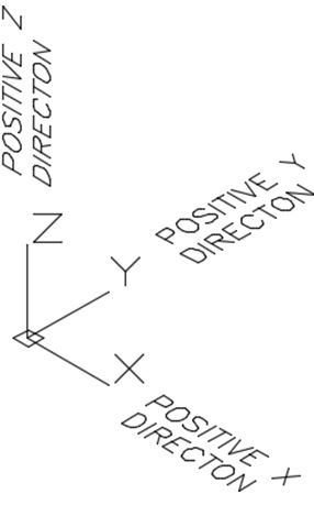
UCS Icon Coordinate Directions
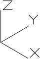
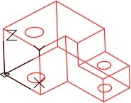
When the UCS is located at the World Coordinate System, it will display a small square at the origin as can be seen in Figure 3-2. If it is located at any other location, it will display as shown in Figure 3-3.
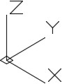
Coordinate System
The Right-Hand Rule
Even though the 3D UCS icon indicates the positive Z direction, it is important to know how it is obtained. AutoCAD uses the right-hand rule to find the positive Z direction. See Figure 3-4. To use the right-hand rule, you must first know the positive X and Y directions of the current UCS.
Using your right hand, point your thumb in the direction of the positive X axis. Extend your index finger in the direction of the positive Y axis. The middle finger indicates the direction of the positive Z axis. By rotating your hand, the X, Y and Z axes will rotate to change the UCS location and orientation. It is important to be able to visualize how and where to move the UCS as you construct more complicated models.
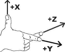
The Right-hand Rule
Drawing with theZ Coordinate
While drawing in 2D, you only had to worry about entering the X and Y coordinates. Since the Z coordinate was omitted, AutoCAD used the default value of zero. When drawing in 3D, you must add the Z value in some coordinate input. For example, to enter the coordinates X2Y3Z4, enter 2,3,4 if it is an absolute coordinate and @2,3,4 if it is a relative coordinate.
Absolute X0Y0Z0
The absolute coordinate 0,0,0 is the origin of the World Coordinate System. This is the same location used in 2D when only 0,0 was entered. This is an important coordinate location as everything drawn in model space relates back to this location. Keep this in mind when drawing all future models. It is especially important when constructing models that relate to real world locations. For example, when drawing a map, X0Y0Z0 is located at the equator and your model must be drawn in relation to that location.
WORK ALONG: Drawing 3D Wireframe Models with the UCS Located at the WCS
Step 1
Using the NEW command, start a new drawing using the template: 3D Layout English.
Step 2
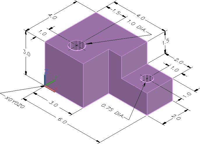
Save the drawing with the name: AutoCAD 3D Workalong 03-1. (Figure Step 2)
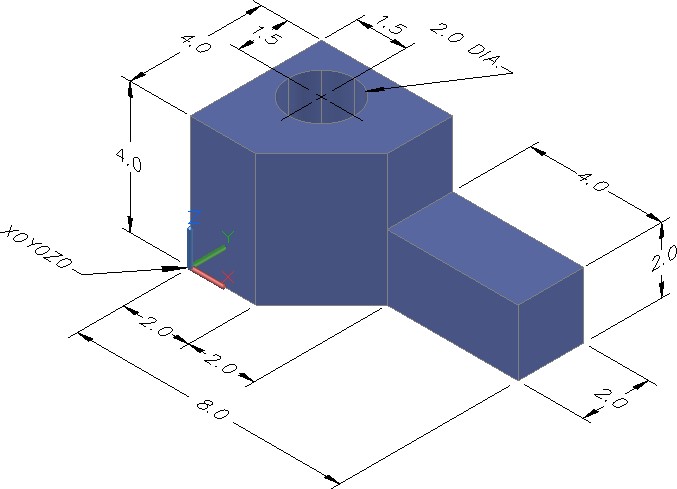
Dimensioned Solid Model
Step 3
Set the current view to SE Isometric. (Figure Step 3)

Step 4
Ensure that the UCS Icon is enabled (On) and the Origin is enabled as shown in Module 1 WORKALONG: Using the UCSICON, VIEW, and 3DFORBIT Commands.
Step 5
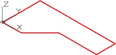
Set layer: Model as the current layer. Enter the LINE command, as shown below, to draw the lines to start the construction of the model. (Figure Step 5)
Command: LINE
Specify first point: 0,0,0
Specify next point or [Undo]: @2,0
(Since you are working at Z zero, you can omit the Z value.)
Specify next point or [Undo]: @2,2
Specify next point or [Close/Undo]: @4,0
Specify next point or [Close/Undo]: @0,2
Specify next point or [Close/Undo]: @-8,0
Specify next point or [Close/Undo]: C
Command:
(Draw the object that is located on the XY axis as you did in 2D.)
Step 6
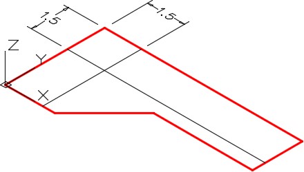
Using the OFFSET command, offset the two lines 1.5 units as shown in the figure. Change the layer properties of the two lines to layer: Construction. (Figure Step 6)
Step 7
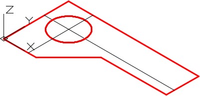
Use the CIRCLE command to draw a 2 diameter circle with its centre located at the intersection of the two construction lines. (Figure Step 7)
Step 8
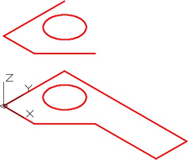
Freeze layer: Construction. Enter the COPY command, as shown below, and copy the three lines and the circle 4 units in the positive Z direction. (Figure Step 8).
Command: COPY
Select objects:
(Select the three lines and the circle as shown in Figure Step 8.)
Select objects:
Specify base point or displacement, or [Multiple]: 0,0,0
Specify second point of displacement or <use first point as displacement>: @0,0,4
(Copy the 4 objects 4 units in the positive Z direction. Looking at the UCS or using the right- hand rule will indicated if it is a positive or negative direction.)
Command:
Step 9
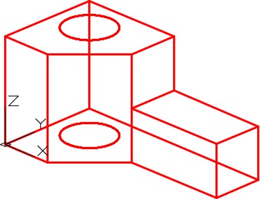
Using the 3DFORBIT command, orbit the model slightly. (Figure Step 9)
Step 10
Using the COPY command, copy the 2 lines 2 units in the positive Z directions. (Figure Step 10)
Step 11
Use the LINE command to draw six lines between the ends of the existing lines. Ensure that you snap to the ends of the lines. (Figure Step 11)
Step 12
Using the COPY command, copy the short line located at the right end of the model two times. Ensure that you use snap mode to locate the lines exactly. (Figure Step 12)
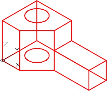
Step 13
Draw three lines between the ends of the existing lines. Ensure to snap to the ends of the existing lines. (Figure Step 13)
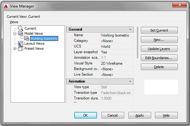
Step 14
Using the VIEW command, save the current view with the name: Working Isometric. (Figure Step 14)
Step 15
Change the current view to SE Isometric. (Figure Step 15)
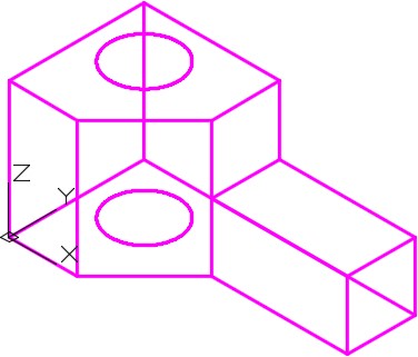
Step 16
Enter the UNITS command. In the Units dialogue box, set the Insertion Units to Inches. Insert the key: AutoCAD 3D Workalong 03-1. It will overlay the model with a magenta model. (Figure Step 16)
Step 17
Save and close the drawing.
WORK ALONG: Drawing 3D Wireframe Models With the UCS Located at the WCS
Step 1
Using the NEW command, start a new drawing using the template: 3D Layout Metric.
Step 2
Save the drawing with the name: AutoCAD 3D Workalong 03-2. (Figure Step 2)
Dimensioned Solid Model
Step 3
Set the current view to SE Isometric. (Figure Step 3)

Step 4
Ensure that the UCS Icon is enabled (On) and the Origin is enabled as shown in Module 1, WORKALONG: Using the UCSICON, VIEW, and 3DFORBIT Commands.
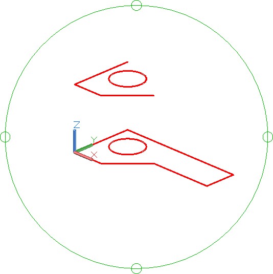
Step 5
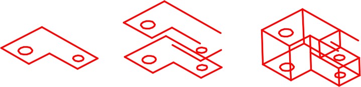
Set layer: Model as the current layer. Draw the shape of the top of the object. Use the ARRAY command to speed up the construction. (Figure Step 5)
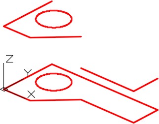
Step 6
Using the COPY command, as shown below, copy all of the objects 10 units in the negative Z direction. (Figure Step 6)
Command: COPY
Select objects:
(Select all objects.)
Select objects:
Specify base point or displacement, or [Multiple]: 0,0,0
Specify second point of displacement or <use first point as displacement>: @0,0,-10
Command:
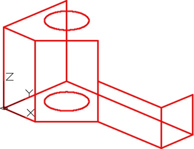
Step 7
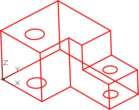
Using the 3DFORBIT command, orbit the model slightly until it appears similar to the figure. (Figure Step 7)
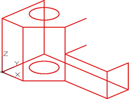
Step 8
Draw the vertical lines by snapping to the endpoints to complete the wireframe model. (Figure Step 8)
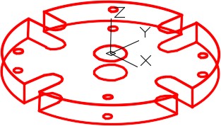
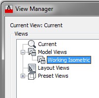
Step 9
Using the VIEW command, save the current view with the name: Working Isometric. (Figure Step 9)
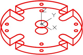
Step 10
Change the view to SE Isometric. (Figure Step 10)
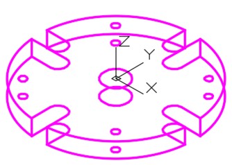
Step 11
Enter the UNITS command. In the Units dialogue box, set the Insertion Units to Millimeters. Insert the key:
AutoCAD 3D Workalong 03-2. It will overlay the model with a magenta model. (Figure Step 11)
Step 12
Save and close the drawing.
Key Principles
Key Principles in Module 3
- AutoCAD has two distinct three dimensional coordinate systems: the World Coordinate System (WCS) and the User Coordinate System (UCS).
- The World Coordinate System is permanently located at the absolute coordinates It is a fixed coordinate system which can never be moved. The WCS is normally not used to construct models.
- The User Coordinate System is the coordinate system that is normally used to construct 3D The UCS can be placed exactly at the WCS or at any location in 3D space.
- AutoCAD uses the right-hand rule to find the positive Z To use the right-hand rule, you must first know the positive X and Y directions of the current UCS. Using your right hand, point the thumb in the direction of the positive X axis. Extend your index finger in the direction of the positive Y axis. Your middle finger indicates the direction of the positive Z axis.
- The absolute coordinate 0,0,0 is the origin of the world coordinate This is the same point used when drawing in 2D when 0,0 was entered. This is an important coordinate location as everything drawn in model space relates back to this location.
Lab Exercise 3-1
Time allowed: 45 minutes.
| Drawing Name | Template | Units |
|---|---|---|
| AutoCAD 3D Lab 03-1 | 3D Layout English | Inches |
Step 1
Save and name the drawing: AutoCAD 3D Lab 03-1.
Step 2
Draw all construction objects on layer: Construction and model objects on layer: Model.
Step 3
Draw a wireframe model of the object shown in the figure. (Figure Step 3A and 3B)
Dimensioned Solid Model
Step 4
Start your model with the current view SE Isometric. If required, orbit it slightly with 3DFORBIT to help the line of sight.
Step 5
Save the isometric working view with the name: Working Isometric.
Step 6
When complete, freeze layer: Construction.
Step 7
Enter the UNITS command. In the Units dialogue box, set the Insertion Units to Inches.
Step 8
Check your drawing with the key. The key name is the same as the drawing name.
Hint 1
Construction Steps
Lab Exercise 3-2
Time allowed: 45 minutes.
| Drawing Name | Template | Units |
|---|---|---|
| AutoCAD 3D Lab 03-2 | 3D Layout English | Millimeters |
Step 1
Save the drawing with the name: AutoCAD 3D Lab 03-2.
Step 2
Draw all construction objects on layer: Construction and all model objects on layer: Model.
Step 3
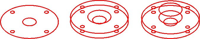
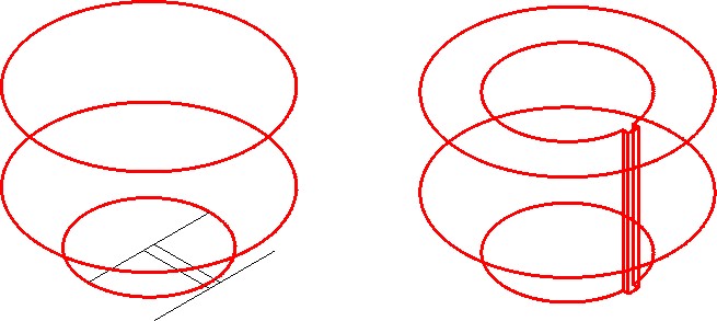
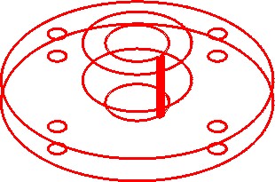
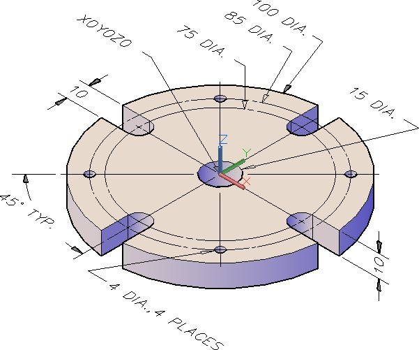
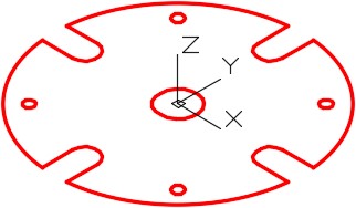
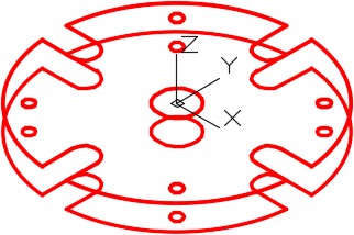
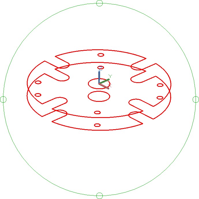
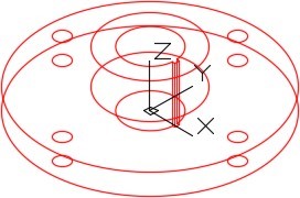
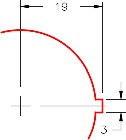
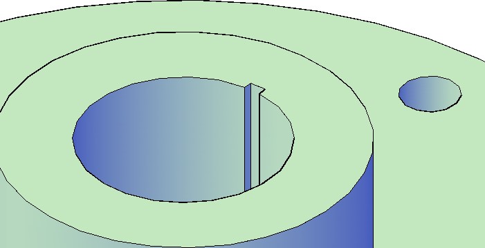
Draw a wireframe model of the object shown in the figure. (Figure Step 3A, 3B, 3C, and 3D)
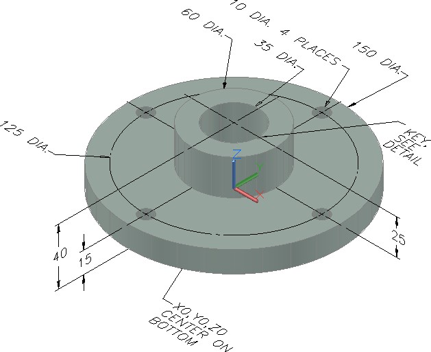
Dimensioned Solid Model
Step 4
Start your model with the current view SE Isometric. If required, orbit it slightly with 3DFORBIT to help the line of sight.
Step 5
Save the isometric working view with the name: Working Isometric.
Step 6
When complete, freeze layer: Construction.
Step 7
Enter the UNITS command. In the Units dialogue box, set the Insertion Units to Millimeters.
Step 8
Check your drawing with the key. The key name is the same as the drawing name.
Hint 1