
2.2: Module 8- Rotating 3D Models
- Page ID
- 19944

\( \newcommand{\vecs}[1]{\overset { \scriptstyle \rightharpoonup} {\mathbf{#1}} } \)
\( \newcommand{\vecd}[1]{\overset{-\!-\!\rightharpoonup}{\vphantom{a}\smash {#1}}} \)
\( \newcommand{\dsum}{\displaystyle\sum\limits} \)
\( \newcommand{\dint}{\displaystyle\int\limits} \)
\( \newcommand{\dlim}{\displaystyle\lim\limits} \)
\( \newcommand{\id}{\mathrm{id}}\) \( \newcommand{\Span}{\mathrm{span}}\)
( \newcommand{\kernel}{\mathrm{null}\,}\) \( \newcommand{\range}{\mathrm{range}\,}\)
\( \newcommand{\RealPart}{\mathrm{Re}}\) \( \newcommand{\ImaginaryPart}{\mathrm{Im}}\)
\( \newcommand{\Argument}{\mathrm{Arg}}\) \( \newcommand{\norm}[1]{\| #1 \|}\)
\( \newcommand{\inner}[2]{\langle #1, #2 \rangle}\)
\( \newcommand{\Span}{\mathrm{span}}\)
\( \newcommand{\id}{\mathrm{id}}\)
\( \newcommand{\Span}{\mathrm{span}}\)
\( \newcommand{\kernel}{\mathrm{null}\,}\)
\( \newcommand{\range}{\mathrm{range}\,}\)
\( \newcommand{\RealPart}{\mathrm{Re}}\)
\( \newcommand{\ImaginaryPart}{\mathrm{Im}}\)
\( \newcommand{\Argument}{\mathrm{Arg}}\)
\( \newcommand{\norm}[1]{\| #1 \|}\)
\( \newcommand{\inner}[2]{\langle #1, #2 \rangle}\)
\( \newcommand{\Span}{\mathrm{span}}\) \( \newcommand{\AA}{\unicode[.8,0]{x212B}}\)
\( \newcommand{\vectorA}[1]{\vec{#1}} % arrow\)
\( \newcommand{\vectorAt}[1]{\vec{\text{#1}}} % arrow\)
\( \newcommand{\vectorB}[1]{\overset { \scriptstyle \rightharpoonup} {\mathbf{#1}} } \)
\( \newcommand{\vectorC}[1]{\textbf{#1}} \)
\( \newcommand{\vectorD}[1]{\overrightarrow{#1}} \)
\( \newcommand{\vectorDt}[1]{\overrightarrow{\text{#1}}} \)
\( \newcommand{\vectE}[1]{\overset{-\!-\!\rightharpoonup}{\vphantom{a}\smash{\mathbf {#1}}}} \)
\( \newcommand{\vecs}[1]{\overset { \scriptstyle \rightharpoonup} {\mathbf{#1}} } \)
\(\newcommand{\longvect}{\overrightarrow}\)
\( \newcommand{\vecd}[1]{\overset{-\!-\!\rightharpoonup}{\vphantom{a}\smash {#1}}} \)
\(\newcommand{\avec}{\mathbf a}\) \(\newcommand{\bvec}{\mathbf b}\) \(\newcommand{\cvec}{\mathbf c}\) \(\newcommand{\dvec}{\mathbf d}\) \(\newcommand{\dtil}{\widetilde{\mathbf d}}\) \(\newcommand{\evec}{\mathbf e}\) \(\newcommand{\fvec}{\mathbf f}\) \(\newcommand{\nvec}{\mathbf n}\) \(\newcommand{\pvec}{\mathbf p}\) \(\newcommand{\qvec}{\mathbf q}\) \(\newcommand{\svec}{\mathbf s}\) \(\newcommand{\tvec}{\mathbf t}\) \(\newcommand{\uvec}{\mathbf u}\) \(\newcommand{\vvec}{\mathbf v}\) \(\newcommand{\wvec}{\mathbf w}\) \(\newcommand{\xvec}{\mathbf x}\) \(\newcommand{\yvec}{\mathbf y}\) \(\newcommand{\zvec}{\mathbf z}\) \(\newcommand{\rvec}{\mathbf r}\) \(\newcommand{\mvec}{\mathbf m}\) \(\newcommand{\zerovec}{\mathbf 0}\) \(\newcommand{\onevec}{\mathbf 1}\) \(\newcommand{\real}{\mathbb R}\) \(\newcommand{\twovec}[2]{\left[\begin{array}{r}#1 \\ #2 \end{array}\right]}\) \(\newcommand{\ctwovec}[2]{\left[\begin{array}{c}#1 \\ #2 \end{array}\right]}\) \(\newcommand{\threevec}[3]{\left[\begin{array}{r}#1 \\ #2 \\ #3 \end{array}\right]}\) \(\newcommand{\cthreevec}[3]{\left[\begin{array}{c}#1 \\ #2 \\ #3 \end{array}\right]}\) \(\newcommand{\fourvec}[4]{\left[\begin{array}{r}#1 \\ #2 \\ #3 \\ #4 \end{array}\right]}\) \(\newcommand{\cfourvec}[4]{\left[\begin{array}{c}#1 \\ #2 \\ #3 \\ #4 \end{array}\right]}\) \(\newcommand{\fivevec}[5]{\left[\begin{array}{r}#1 \\ #2 \\ #3 \\ #4 \\ #5 \\ \end{array}\right]}\) \(\newcommand{\cfivevec}[5]{\left[\begin{array}{c}#1 \\ #2 \\ #3 \\ #4 \\ #5 \\ \end{array}\right]}\) \(\newcommand{\mattwo}[4]{\left[\begin{array}{rr}#1 \amp #2 \\ #3 \amp #4 \\ \end{array}\right]}\) \(\newcommand{\laspan}[1]{\text{Span}\{#1\}}\) \(\newcommand{\bcal}{\cal B}\) \(\newcommand{\ccal}{\cal C}\) \(\newcommand{\scal}{\cal S}\) \(\newcommand{\wcal}{\cal W}\) \(\newcommand{\ecal}{\cal E}\) \(\newcommand{\coords}[2]{\left\{#1\right\}_{#2}}\) \(\newcommand{\gray}[1]{\color{gray}{#1}}\) \(\newcommand{\lgray}[1]{\color{lightgray}{#1}}\) \(\newcommand{\rank}{\operatorname{rank}}\) \(\newcommand{\row}{\text{Row}}\) \(\newcommand{\col}{\text{Col}}\) \(\renewcommand{\row}{\text{Row}}\) \(\newcommand{\nul}{\text{Nul}}\) \(\newcommand{\var}{\text{Var}}\) \(\newcommand{\corr}{\text{corr}}\) \(\newcommand{\len}[1]{\left|#1\right|}\) \(\newcommand{\bbar}{\overline{\bvec}}\) \(\newcommand{\bhat}{\widehat{\bvec}}\) \(\newcommand{\bperp}{\bvec^\perp}\) \(\newcommand{\xhat}{\widehat{\xvec}}\) \(\newcommand{\vhat}{\widehat{\vvec}}\) \(\newcommand{\uhat}{\widehat{\uvec}}\) \(\newcommand{\what}{\widehat{\wvec}}\) \(\newcommand{\Sighat}{\widehat{\Sigma}}\) \(\newcommand{\lt}{<}\) \(\newcommand{\gt}{>}\) \(\newcommand{\amp}{&}\) \(\definecolor{fillinmathshade}{gray}{0.9}\)Module 8: Rotating 3D Models
Learning Outcomes
When you have completed this module, you will be able to:
- Apply the TRIM and EXTEND commands when trimming and extending in three dimensional wireframe modeling.
- Apply the ROTATE3D command to rotate 3D models.
Rotating in 3D
AutoCAD has individual 2D and 3D rotate commands. The 2D rotate command is ROTATE and in 3D, it is ROTATE3D. In this module, using the ROTATE3D command will be taught. It is used to rotate the model in 3D space. The main difference between the two commands is that the ROTATE command uses a XY point to rotate around and the ROTATE3D command uses two XYZ points or an axis to rotated around. The ROTATE command can be used while 3D modeling as long as all of the objects being rotated are 2D objects and located on the current UCS. If 3D objects are going to be rotated in 3D space, the ROTATE3D command must be used. See Figure 8-1.
Rotating 3D Model in 3D Space
AutoCAD Command: ROTATE3D
The ROTATE3D command is used to rotate objects in 3D space around an axis or two XY points.
Shortcut: none
WORK ALONG: Rotating Wireframe Models in 3D Space
Step 1
Using the NEW command, start a new drawing using the template: 3D Layout English.
Step 2
Save and name the drawing: AutoCAD 3D Workalong 08-1.
Step 3
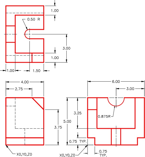
On layer: Model, draw a wireframe model of the object shown in the multiview drawing. (Figure Step 3A and 3B)
Dimensioned Multiview Drawing
SE Isometric View
Step 4
Enter the commands, as shown below, to set the TRIM and EXTEND commands while working in 3D.
Command: TRIM
Current settings: Projection=None, Edge=No Extend
(Note how in this case, the Projection is set to None and Edge to No Extend. Your computer might be different.)
Select cutting edges … (Select an object, any object)
Select objects or <select all>: (Press Enter)
Select object to trim or shift-select to extend or [Fence/Crossing/Project/Edge/eRase/Undo]: P
Enter a projection option [None/Ucs/View] <None>: U
(Enter U for Ucs.)
[Fence/Crossing/Project/Edge/eRase/Undo]: E
Enter an implied edge extension mode [Extend/No extend] <No Extend>: E
(Enter E for Edge and then another for Extend. That means that the intersection of the two objects that you are trimming or extending do not have to physically intersect. AutoCAD will extend them to find the apparent intersection for you.)
Command: EXTEND
Current settings: Projection=Ucs, Edge=Extend
Select cutting edges …
Select objects or <select all>:
(By entering the EXTEND command, you will now see the settings are set for this command as well.)
Command:
Step 5
Enter the TRIM command as shown below. The Current settings: should be set as shown. If not, go back and redo Step 4. If they match, abort the command.
Command: TRIM
Current settings: Projection=UCS, Edge=Extend
Select boundary edges …
Step 6
Enter the ROTATE3D, as shown below, to rotate the model 90 degrees counterclockwise around the X axis. (Figure Step 6)
Command: ROTATE3D
Current positive angle: ANGDIR=counterclockwise ANGBASE=0
Select objects:
Specify opposite corner: 22 found
(Using a window, select all the objects)
Select objects:
Specify first point on axis or define axis by [Object/Last/View/Xaxis/Yaxis/Zaxis/2points]: X
(Rotate around the X axis.)
Specify a point on the X axis <0,0,0>:
(Press Enter to select 0,0,0 as the base point of the rotation.)
Specify rotation angle or [Reference]: 90
(The angle is positive since looking along the X axis towards 0,0,0, counterclockwise is the direction you want to rotate.)
Command:
Step 7
Using what you learned in Step 6, rotate the model 90 degrees around the Y axis. This rotation will have be negative 90 degrees since the rotation is clockwise. (Figure Step 7)
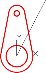
Step 8
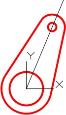
Change the UCS to the front and locate it at the centre of the circle. (Figure Step 8)
Step 9
On layer: Construction, draw a line from 0,0,0 at any angle and any length. The line you draw does not have to match the figure exactly. Draw it by eye. (Figure step 9)
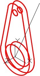
Step 10
Change to the Front view to ensure that the line was drawn correctly. (Figure Step 10)
MUST KNOW: The TRIM and EXTEND commands should have the following default settings when working in 3D:
Current settings: Projection=UCS, Edge=Extend
Step 11
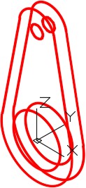
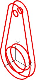
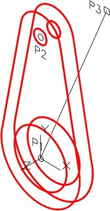
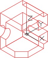
Change the current view to SE Isometric and enter the ROTATE3D command, as shown below, to rotate the model using the Reference option. (Figure Step 11)
Command: ROTATE3D
Current positive angle: ANGDIR=counterclockwise ANGBASE=0
Select objects:
(Select all of the model objects in a window. Do not include the reference line that you just drew in the selection.)
Specify opposite corner: 22 found
Select objects:
Specify first point on axis or define axis by
[Object/Last/View/Xaxis/Yaxis/Zaxis/2points]: Z
(Rotating around the Z axis.)
Specify a point on the Z axis <0,0,0>:
Specify rotation angle or [Reference]: R
Specify the reference angle <0>: (cen) P1
Specify second point: (cen) P2
Specify the new angle: (cen) P1
(Note that you have to select the P1 location twice.)
Specify second point: (end) P3
Command:
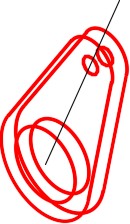
Step 12
The wireframe model should now appear as shown in Figure Step 12A. Change the current view to Front to ensure that the model was rotated correctly. (Figure Step 12A and 12B)
Step 13
Save and close the drawing.
USER TIP: When using the ROTATE3D command, ensure that the ANGDIR and ANGBASE system variables are set as shown below. These setting will display when you enter the command, as you can see below. After you become more familiar using 3D, you can change these settings. While working on the AutoCAD 3D book, leave them set as shown.
Command: ROTATE3D
Current positive angle: ANGDIR=counterclockwise ANGBASE=0
Key Principles
Key Principles in Module 8
- While working in 3D, the TRIM and EXTEND commands should have the following default settings: Projection=UCS, Edge=Extend
- The ROTATE command, used for a 2D rotate, uses a XY point to rotate For a 3D rotate using the ROTATE3D command, one of the axises, a line or two XYZ points must be specified to rotate around.
- To find whether the 3D rotation direction is counterclockwise or clockwise, look at 0,0,0 from the positive end of the axis you are rotating around.
Lab Exercise 8-1
Time allowed: 60 minutes.
| Drawing Name | Template | Units |
|---|---|---|
| AutoCAD 3D Lab 08-1 | 3D Layout English | Inches |
Step 1
Draw all construction objects on layer: Construction and all model objects on layer: Model.
Step 2
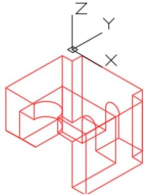
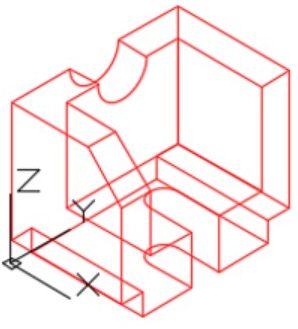
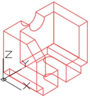
Draw a wireframe model of the object shown in the figure. (Figure Step 2A, 2B, 2C,and 2D)
Step 3
When complete, freeze layer: Construction.
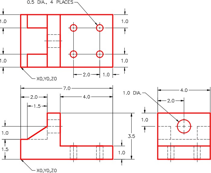
Dimensioned Multiview Drawing
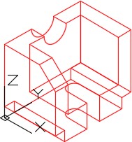
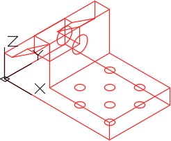
Completed Wireframe Model SE Isometric View
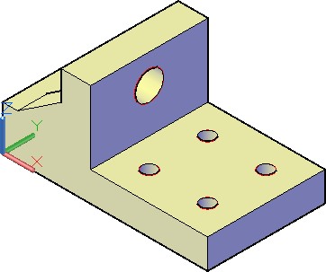
Solid Model – SE Isometric View
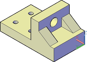
Solid Model – NE Isometric View
Step 4
Enter the UNITS command. In the Units dialogue box, set the Insertion Units to Inches. Change the location of the UCS to World and check the model with the key.
Step 5
Ensure that the USC is set to World and the current view is SE Isometric. (Figure Step 5)
Step 6
Rotate the model 90 degrees around the X axis. (Figure Step 6)
Step 7
Rotate the model 90 degrees around the Y axis. (Figure Step 7)
Step 8
Rotate the model 90 degrees around the X axis. (Figure Step 8)
Step 9
Rotate the model 90 degrees around the Z axis. (Figure Step 9)
Step 10
Save and close the drawing.
Lab Exercise 8-2
Time allowed: 40 minutes.
| Drawing Name | Template | Units |
|---|---|---|
| AutoCAD 3D Lab 08-2 | 3D Layout English | Inches |
Step 1
Draw all construction objects on layer: Construction and all model objects on layer: Model.
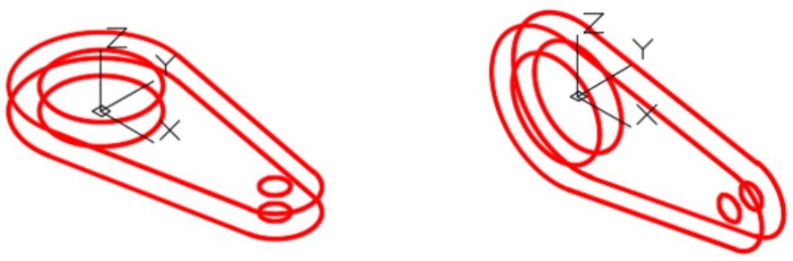
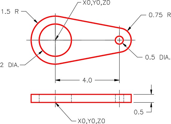
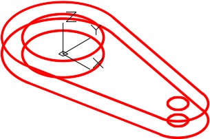
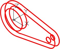
Step 2
Draw a wireframe model of the object shown in the figure. (Figure Step 2A, 2B, 2C, and 2D)
Step 3
When complete, freeze layer: Construction.
Dimensioned Multiview Drawing
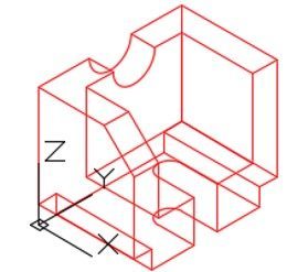
Completed Wireframe Model SE Isometric View
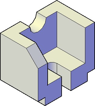
Solid Model SE Isometric View
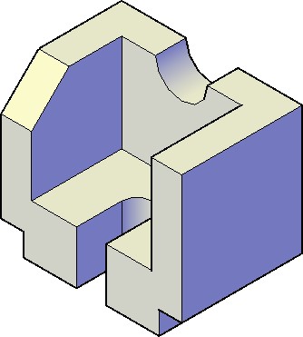
Solid Model NW Isometric View
Step 4
Enter the UNITS command. In the Units dialogue box, set the Insertion Units to Inches. Change the location of the UCS to World and check the model with the key.
Step 5
Save and close the drawing.