4.5: Module 21 Competency Test No.4 Open Book
- Page ID
- 19968

\( \newcommand{\vecs}[1]{\overset { \scriptstyle \rightharpoonup} {\mathbf{#1}} } \)
\( \newcommand{\vecd}[1]{\overset{-\!-\!\rightharpoonup}{\vphantom{a}\smash {#1}}} \)
\( \newcommand{\id}{\mathrm{id}}\) \( \newcommand{\Span}{\mathrm{span}}\)
( \newcommand{\kernel}{\mathrm{null}\,}\) \( \newcommand{\range}{\mathrm{range}\,}\)
\( \newcommand{\RealPart}{\mathrm{Re}}\) \( \newcommand{\ImaginaryPart}{\mathrm{Im}}\)
\( \newcommand{\Argument}{\mathrm{Arg}}\) \( \newcommand{\norm}[1]{\| #1 \|}\)
\( \newcommand{\inner}[2]{\langle #1, #2 \rangle}\)
\( \newcommand{\Span}{\mathrm{span}}\)
\( \newcommand{\id}{\mathrm{id}}\)
\( \newcommand{\Span}{\mathrm{span}}\)
\( \newcommand{\kernel}{\mathrm{null}\,}\)
\( \newcommand{\range}{\mathrm{range}\,}\)
\( \newcommand{\RealPart}{\mathrm{Re}}\)
\( \newcommand{\ImaginaryPart}{\mathrm{Im}}\)
\( \newcommand{\Argument}{\mathrm{Arg}}\)
\( \newcommand{\norm}[1]{\| #1 \|}\)
\( \newcommand{\inner}[2]{\langle #1, #2 \rangle}\)
\( \newcommand{\Span}{\mathrm{span}}\) \( \newcommand{\AA}{\unicode[.8,0]{x212B}}\)
\( \newcommand{\vectorA}[1]{\vec{#1}} % arrow\)
\( \newcommand{\vectorAt}[1]{\vec{\text{#1}}} % arrow\)
\( \newcommand{\vectorB}[1]{\overset { \scriptstyle \rightharpoonup} {\mathbf{#1}} } \)
\( \newcommand{\vectorC}[1]{\textbf{#1}} \)
\( \newcommand{\vectorD}[1]{\overrightarrow{#1}} \)
\( \newcommand{\vectorDt}[1]{\overrightarrow{\text{#1}}} \)
\( \newcommand{\vectE}[1]{\overset{-\!-\!\rightharpoonup}{\vphantom{a}\smash{\mathbf {#1}}}} \)
\( \newcommand{\vecs}[1]{\overset { \scriptstyle \rightharpoonup} {\mathbf{#1}} } \)
\( \newcommand{\vecd}[1]{\overset{-\!-\!\rightharpoonup}{\vphantom{a}\smash {#1}}} \)
\(\newcommand{\avec}{\mathbf a}\) \(\newcommand{\bvec}{\mathbf b}\) \(\newcommand{\cvec}{\mathbf c}\) \(\newcommand{\dvec}{\mathbf d}\) \(\newcommand{\dtil}{\widetilde{\mathbf d}}\) \(\newcommand{\evec}{\mathbf e}\) \(\newcommand{\fvec}{\mathbf f}\) \(\newcommand{\nvec}{\mathbf n}\) \(\newcommand{\pvec}{\mathbf p}\) \(\newcommand{\qvec}{\mathbf q}\) \(\newcommand{\svec}{\mathbf s}\) \(\newcommand{\tvec}{\mathbf t}\) \(\newcommand{\uvec}{\mathbf u}\) \(\newcommand{\vvec}{\mathbf v}\) \(\newcommand{\wvec}{\mathbf w}\) \(\newcommand{\xvec}{\mathbf x}\) \(\newcommand{\yvec}{\mathbf y}\) \(\newcommand{\zvec}{\mathbf z}\) \(\newcommand{\rvec}{\mathbf r}\) \(\newcommand{\mvec}{\mathbf m}\) \(\newcommand{\zerovec}{\mathbf 0}\) \(\newcommand{\onevec}{\mathbf 1}\) \(\newcommand{\real}{\mathbb R}\) \(\newcommand{\twovec}[2]{\left[\begin{array}{r}#1 \\ #2 \end{array}\right]}\) \(\newcommand{\ctwovec}[2]{\left[\begin{array}{c}#1 \\ #2 \end{array}\right]}\) \(\newcommand{\threevec}[3]{\left[\begin{array}{r}#1 \\ #2 \\ #3 \end{array}\right]}\) \(\newcommand{\cthreevec}[3]{\left[\begin{array}{c}#1 \\ #2 \\ #3 \end{array}\right]}\) \(\newcommand{\fourvec}[4]{\left[\begin{array}{r}#1 \\ #2 \\ #3 \\ #4 \end{array}\right]}\) \(\newcommand{\cfourvec}[4]{\left[\begin{array}{c}#1 \\ #2 \\ #3 \\ #4 \end{array}\right]}\) \(\newcommand{\fivevec}[5]{\left[\begin{array}{r}#1 \\ #2 \\ #3 \\ #4 \\ #5 \\ \end{array}\right]}\) \(\newcommand{\cfivevec}[5]{\left[\begin{array}{c}#1 \\ #2 \\ #3 \\ #4 \\ #5 \\ \end{array}\right]}\) \(\newcommand{\mattwo}[4]{\left[\begin{array}{rr}#1 \amp #2 \\ #3 \amp #4 \\ \end{array}\right]}\) \(\newcommand{\laspan}[1]{\text{Span}\{#1\}}\) \(\newcommand{\bcal}{\cal B}\) \(\newcommand{\ccal}{\cal C}\) \(\newcommand{\scal}{\cal S}\) \(\newcommand{\wcal}{\cal W}\) \(\newcommand{\ecal}{\cal E}\) \(\newcommand{\coords}[2]{\left\{#1\right\}_{#2}}\) \(\newcommand{\gray}[1]{\color{gray}{#1}}\) \(\newcommand{\lgray}[1]{\color{lightgray}{#1}}\) \(\newcommand{\rank}{\operatorname{rank}}\) \(\newcommand{\row}{\text{Row}}\) \(\newcommand{\col}{\text{Col}}\) \(\renewcommand{\row}{\text{Row}}\) \(\newcommand{\nul}{\text{Nul}}\) \(\newcommand{\var}{\text{Var}}\) \(\newcommand{\corr}{\text{corr}}\) \(\newcommand{\len}[1]{\left|#1\right|}\) \(\newcommand{\bbar}{\overline{\bvec}}\) \(\newcommand{\bhat}{\widehat{\bvec}}\) \(\newcommand{\bperp}{\bvec^\perp}\) \(\newcommand{\xhat}{\widehat{\xvec}}\) \(\newcommand{\vhat}{\widehat{\vvec}}\) \(\newcommand{\uhat}{\widehat{\uvec}}\) \(\newcommand{\what}{\widehat{\wvec}}\) \(\newcommand{\Sighat}{\widehat{\Sigma}}\) \(\newcommand{\lt}{<}\) \(\newcommand{\gt}{>}\) \(\newcommand{\amp}{&}\) \(\definecolor{fillinmathshade}{gray}{0.9}\)Module 21 Competency Test No.4 Open Book
Learning Outcomes
When you have completed this module, you will be able to:
- Within a four hour time limit, complete a written exam and the lab exercises without the aid of a key.
The AutoCAD 3D book was written with competency based modules. What that means is that you have not completed each module until you have mastered it. The Competency Test module contains multiple choice questions and a comprehensive lab exercise to test your mastery of the set of modules that you completed. There are no answers or keys supplied in a Competency Test module since it is meant to be checked by your instructor. If there are any parts of this module that you have trouble completing, you should go back and reread the module or modules containing the information that you are having trouble with. If necessary, redo as many lab exercises required until you fully understand the material.
If you are completing this book:
- Without the aid of an instructor, complete the written test and the lab exercise.
- In a classroom with an instructor, the instructor will give instructions on what to do after this module has been completed.
Multiple Choice Questions
Select the BEST answer.
- Which one of the following best describes the INTERSECT command?
- It create a solid by finding the volume shared by two or more solids.
- It create a solid by subtracting one solid from another.
- It create a solid by joining two or more solids together.
- It create a solid by subtracting the largest solid from the smallest one.
- It create a solid by subtracting the smallest solid from the largest one.
- What command joins two or more solids into one solid object?
- SUBTRACT
- EXTRUDE
- UNION
- JOIN
- INTERSECT
- Which one of the following primitives cannot be created using the REVOLVE command?
- Cone
- Cylinder
- Sphere
- Torus
- Box
- What command creates a solid by revolving a 2D shape around an axis?
- SUBTRACT
- EXTRUDE
- REVOLVE
- JOIN
- INTERSECT
- What system variable is used to set the number of contour lines that will be used when a curved solid is constructed?
- SOLIDLINES
- SURTAB1
- LINEISO
- ISOLINES
- SUFTAB2
- Which direction, on the current UCS, does the EXTRUDE command project the closed object to create a solid model?
- X
- Y
- Either X or Y
- Z
- Either X, Y or Z
- Which one of the following statements is false?
- A surfaced model is hollow.
- The mass properties of a solid model can be obtained.
- A solid model Is the best computerized representation of an object.
- A solid model is solid.
- The mass properties of a surfaced model can be obtained.
- What type of object is created by the SECTION command?
- Solid
- Closed polyline
- Region
- Hatch
- Open polyline
- Which one of the following is not a solid primitive?
- Wedge
- Sphere
- Rectangle
- Box
- Cylinder
- What command removes one solid from another solid?
- SUBTRACT
- EXTRUDE
- REVOLVE
- JOIN
- INTERSECT
Lab Exercise 21-1A OPEN BOOK
| Drawing Name | Template | Units |
|---|---|---|
| AutoCAD 3D Lab 21-1A | 3D Layout English | Inches |
Step 1
Draw all plines on layer: Pline.
Step 2
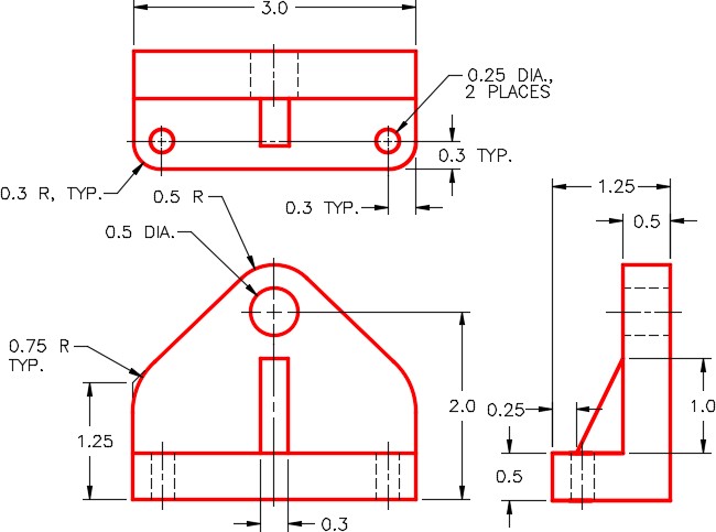
On layer: Solid Base, create a solid model of the Base. (Figure Step 2A and 2B)
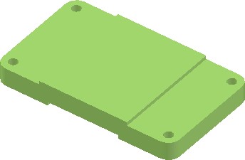
Solid Model of the Base
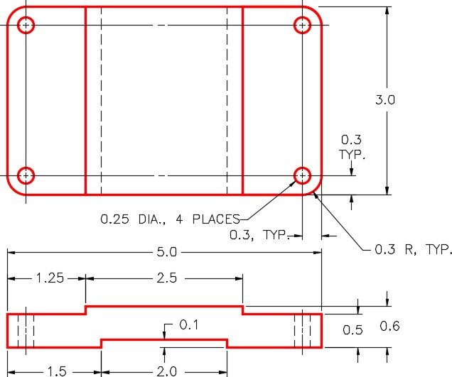
Dimensioned Multiview Drawing of the Base
Step 3
Create a block of the model. Name it:
AutoCAD 3D Lab 21-1A. Pick an appropriate location for 0,0,0. Set 0,0,0 as the insert point for the block. Make 0,0,0 as the insert point for the block. Ensure that the current UCS is located at the World when creating the block.
Lab Exercise 21-1B OPEN BOOK
| Drawing Name | Template | Units |
|---|---|---|
| AutoCAD 3D Lab 21-1B | 3D Layout English | Inches |
Step 1
Draw all plines on layer: Pline.
Step 2
On layer: Construction, add any necessary construction objects that will help insert the model into the assembly.
Step 3
On layer: Solid Support, create a solid model of the Support. (Figure Step 3A and 3B)
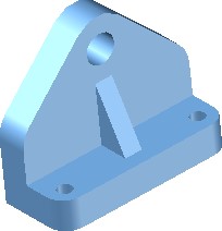
Solid Model of the Support
Dimensioned Multiview Drawing of the Support
Step 4
Create a block of the model. Name it: AutoCAD 3D Lab 21-1B. Pick an appropriate location for 0,0,0. Set 0,0,0 as the insert point for the block. Ensure that the current UCS is located at the World when creating the block.
Lab Exercise 21-1C OPEN BOOK
| Drawing Name | Template | Units |
|---|---|---|
| AutoCAD 3D Lab 21-1C | 3D Layout English | Inches |
Step 1
Draw all plines on layer: Pline.
Step 2
On layer: Construction, add any necessary construction objects that will help insert the model into the assembly.
Step 3
On layer: Solid Axle, create a solid model of the Axle. (Figure Step 3A and 3B)
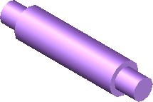
Solid Model of the Axle
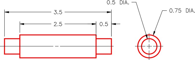
Dimensioned Multiview Drawing of the Axle
Step 4
Create a block of the model. Name it: AutoCAD 3D Lab 21-1C. Pick an appropriate location for 0,0,0. Set 0,0,0 as the insert point for the block. Ensure that the current UCS is located at the World when creating the block.
Lab Exercise 21-1D OPEN BOOK
| Drawing Name | Template | Units |
|---|---|---|
| AutoCAD 3D Lab 21-1D | 3D Layout English | Inches |
Step 1
Draw all plines on layer: Pline.
Step 2
On layer: Construction, add any necessary construction objects that will help insert the model into the assembly.
Step 3
On layer: Solid Wheel, create a solid model of the Wheel. (Figure Step 3A and 3B)
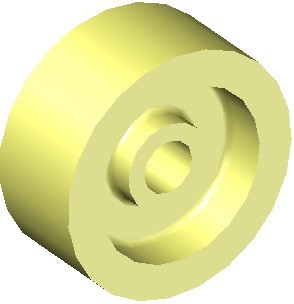
Solid Model of the Wheel
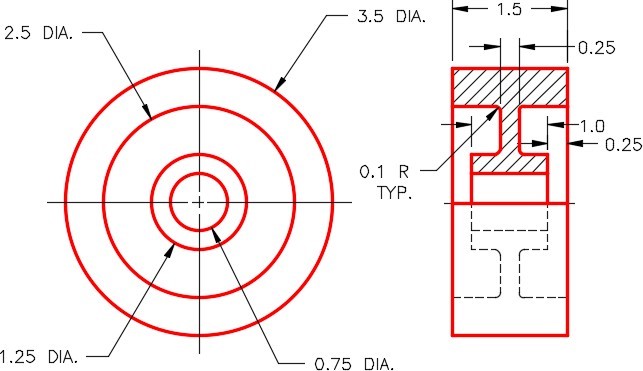
Dimensioned Multiview Drawing of the Wheel
Step 4
Create a block of the model. Name it: AutoCAD 3D Lab 21-1D. Pick an appropriate location for 0,0,0. Make 0,0,0 as the insert point for the block. Ensure that the current UCS is located at the World when creating the block.
Lab Exercise 21-1E OPEN BOOK
| Drawing Name | Template | Units |
|---|---|---|
| AutoCAD 3D Lab 21-1E | 3D Layout English | Inches |
Step 1
Draw all plines on layer: Pline.
Step 2
On layer Construction, add any necessary construction objects that will help insert the model into the assembly.
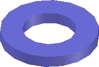
Step 3
On layer: Solid Washer, create a solid model of the Washer. (Figure Step 3A and 3B)
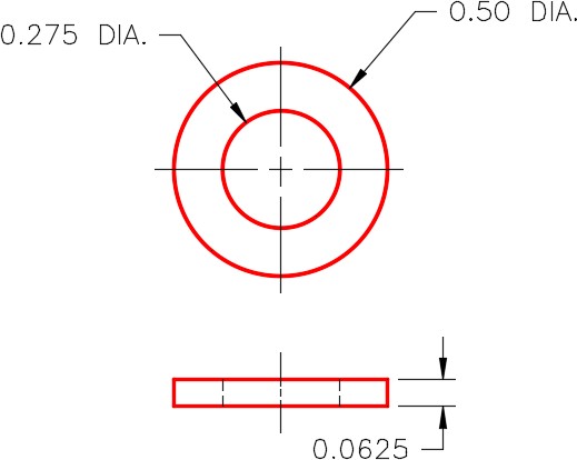
Dimensioned Multiview Drawing of the Washer
Step 4
Create a block of the model. Name it: AutoCAD 3D Lab 21-1E. Pick an appropriate location for 0,0,0. Set 0,0,0 as the insert point for your block. Ensure that the current UCS is located at the World when creating the block.
Lab Exercise 21-1F OPEN BOOK
| Drawing Name | Template | Units |
|---|---|---|
| AutoCAD 3D Lab 21-1F | 3D Layout English | Inches |
Step 1
Draw all plines on layer: Pline.
Step 2
On layer Construction, add any necessary construction objects that will help insert the model into the assembly.
Step 3
On layer: Solid Bolt, create a solid model of the Bolt. (Figure Step 3A and 3B)

Bolt
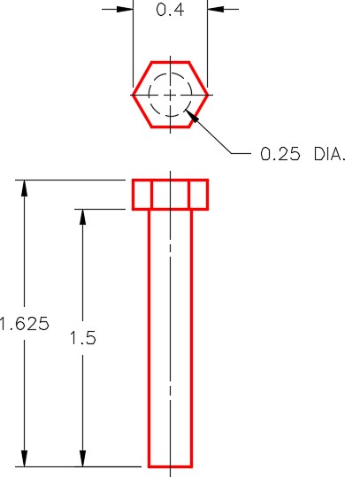
Dimensioned Multiview Drawing of the Bolt
Step 4
Create a block of the model. Name it: AutoCAD 3D Lab 21-1F. Pick an appropriate location for 0,0,0. Set 0,0,0 as the insert point for your block. Ensure that the current UCS is located at the World when creating the block.
Lab Exercise 21-1 OPEN BOOK
| Drawing Name | Template | Units |
|---|---|---|
| AutoCAD 3D Lab 21-1 | 3D Layout English | Inches |
Step 1
Start a new drawing and save it with the name: AutoCAD 3D Lab 21-1.
Step 2
Open the six drawings that you created earlier in this lab exercise.
Step 3
Set the current UCS to World and using DesignCenter insert the following blocks into the drawing.
1- AutoCAD 3D Lab 21-1A
2- AutoCAD 3D Lab 21-1B
1- AutoCAD 3D Lab 21-1C
1- AutoCAD 3D Lab 21-1D
4- AutoCAD 3D Lab 21-1E
4- AutoCAD 3D Lab 21-1F
Step 4
Close all drawings except for: AutoCAD 3D Lab 21-1
Step 5
Ensure that layers: Pline and Construction are on and all solid layers are off. Move the blocks into their exact location to create the assembly using the model or construction objects locate them accurately.
Step 6
Turn on all solid layers and turn off the layers: Pline and Construction.
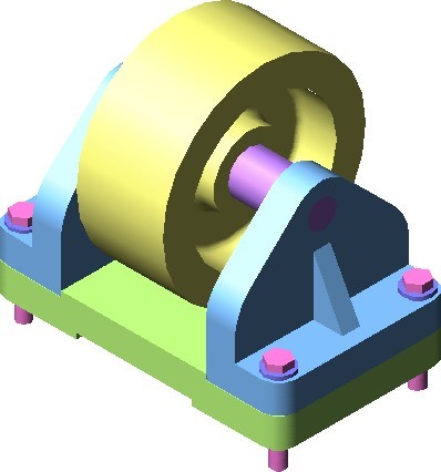
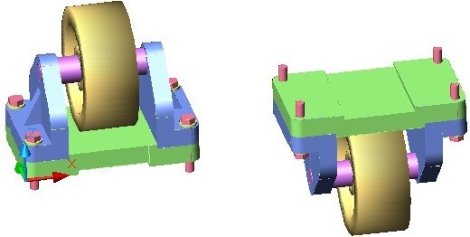
Step 7
With UCS in World, copy the complete Caster Assembly 10 inches in the X direction. Rotate the copy of the assembly 180 degrees around the X axis into the position it would be installed. (Figure Step 7)