
5.3: Module 29 Shell
- Page ID
- 19971

\( \newcommand{\vecs}[1]{\overset { \scriptstyle \rightharpoonup} {\mathbf{#1}} } \)
\( \newcommand{\vecd}[1]{\overset{-\!-\!\rightharpoonup}{\vphantom{a}\smash {#1}}} \)
\( \newcommand{\id}{\mathrm{id}}\) \( \newcommand{\Span}{\mathrm{span}}\)
( \newcommand{\kernel}{\mathrm{null}\,}\) \( \newcommand{\range}{\mathrm{range}\,}\)
\( \newcommand{\RealPart}{\mathrm{Re}}\) \( \newcommand{\ImaginaryPart}{\mathrm{Im}}\)
\( \newcommand{\Argument}{\mathrm{Arg}}\) \( \newcommand{\norm}[1]{\| #1 \|}\)
\( \newcommand{\inner}[2]{\langle #1, #2 \rangle}\)
\( \newcommand{\Span}{\mathrm{span}}\)
\( \newcommand{\id}{\mathrm{id}}\)
\( \newcommand{\Span}{\mathrm{span}}\)
\( \newcommand{\kernel}{\mathrm{null}\,}\)
\( \newcommand{\range}{\mathrm{range}\,}\)
\( \newcommand{\RealPart}{\mathrm{Re}}\)
\( \newcommand{\ImaginaryPart}{\mathrm{Im}}\)
\( \newcommand{\Argument}{\mathrm{Arg}}\)
\( \newcommand{\norm}[1]{\| #1 \|}\)
\( \newcommand{\inner}[2]{\langle #1, #2 \rangle}\)
\( \newcommand{\Span}{\mathrm{span}}\) \( \newcommand{\AA}{\unicode[.8,0]{x212B}}\)
\( \newcommand{\vectorA}[1]{\vec{#1}} % arrow\)
\( \newcommand{\vectorAt}[1]{\vec{\text{#1}}} % arrow\)
\( \newcommand{\vectorB}[1]{\overset { \scriptstyle \rightharpoonup} {\mathbf{#1}} } \)
\( \newcommand{\vectorC}[1]{\textbf{#1}} \)
\( \newcommand{\vectorD}[1]{\overrightarrow{#1}} \)
\( \newcommand{\vectorDt}[1]{\overrightarrow{\text{#1}}} \)
\( \newcommand{\vectE}[1]{\overset{-\!-\!\rightharpoonup}{\vphantom{a}\smash{\mathbf {#1}}}} \)
\( \newcommand{\vecs}[1]{\overset { \scriptstyle \rightharpoonup} {\mathbf{#1}} } \)
\( \newcommand{\vecd}[1]{\overset{-\!-\!\rightharpoonup}{\vphantom{a}\smash {#1}}} \)
\(\newcommand{\avec}{\mathbf a}\) \(\newcommand{\bvec}{\mathbf b}\) \(\newcommand{\cvec}{\mathbf c}\) \(\newcommand{\dvec}{\mathbf d}\) \(\newcommand{\dtil}{\widetilde{\mathbf d}}\) \(\newcommand{\evec}{\mathbf e}\) \(\newcommand{\fvec}{\mathbf f}\) \(\newcommand{\nvec}{\mathbf n}\) \(\newcommand{\pvec}{\mathbf p}\) \(\newcommand{\qvec}{\mathbf q}\) \(\newcommand{\svec}{\mathbf s}\) \(\newcommand{\tvec}{\mathbf t}\) \(\newcommand{\uvec}{\mathbf u}\) \(\newcommand{\vvec}{\mathbf v}\) \(\newcommand{\wvec}{\mathbf w}\) \(\newcommand{\xvec}{\mathbf x}\) \(\newcommand{\yvec}{\mathbf y}\) \(\newcommand{\zvec}{\mathbf z}\) \(\newcommand{\rvec}{\mathbf r}\) \(\newcommand{\mvec}{\mathbf m}\) \(\newcommand{\zerovec}{\mathbf 0}\) \(\newcommand{\onevec}{\mathbf 1}\) \(\newcommand{\real}{\mathbb R}\) \(\newcommand{\twovec}[2]{\left[\begin{array}{r}#1 \\ #2 \end{array}\right]}\) \(\newcommand{\ctwovec}[2]{\left[\begin{array}{c}#1 \\ #2 \end{array}\right]}\) \(\newcommand{\threevec}[3]{\left[\begin{array}{r}#1 \\ #2 \\ #3 \end{array}\right]}\) \(\newcommand{\cthreevec}[3]{\left[\begin{array}{c}#1 \\ #2 \\ #3 \end{array}\right]}\) \(\newcommand{\fourvec}[4]{\left[\begin{array}{r}#1 \\ #2 \\ #3 \\ #4 \end{array}\right]}\) \(\newcommand{\cfourvec}[4]{\left[\begin{array}{c}#1 \\ #2 \\ #3 \\ #4 \end{array}\right]}\) \(\newcommand{\fivevec}[5]{\left[\begin{array}{r}#1 \\ #2 \\ #3 \\ #4 \\ #5 \\ \end{array}\right]}\) \(\newcommand{\cfivevec}[5]{\left[\begin{array}{c}#1 \\ #2 \\ #3 \\ #4 \\ #5 \\ \end{array}\right]}\) \(\newcommand{\mattwo}[4]{\left[\begin{array}{rr}#1 \amp #2 \\ #3 \amp #4 \\ \end{array}\right]}\) \(\newcommand{\laspan}[1]{\text{Span}\{#1\}}\) \(\newcommand{\bcal}{\cal B}\) \(\newcommand{\ccal}{\cal C}\) \(\newcommand{\scal}{\cal S}\) \(\newcommand{\wcal}{\cal W}\) \(\newcommand{\ecal}{\cal E}\) \(\newcommand{\coords}[2]{\left\{#1\right\}_{#2}}\) \(\newcommand{\gray}[1]{\color{gray}{#1}}\) \(\newcommand{\lgray}[1]{\color{lightgray}{#1}}\) \(\newcommand{\rank}{\operatorname{rank}}\) \(\newcommand{\row}{\text{Row}}\) \(\newcommand{\col}{\text{Col}}\) \(\renewcommand{\row}{\text{Row}}\) \(\newcommand{\nul}{\text{Nul}}\) \(\newcommand{\var}{\text{Var}}\) \(\newcommand{\corr}{\text{corr}}\) \(\newcommand{\len}[1]{\left|#1\right|}\) \(\newcommand{\bbar}{\overline{\bvec}}\) \(\newcommand{\bhat}{\widehat{\bvec}}\) \(\newcommand{\bperp}{\bvec^\perp}\) \(\newcommand{\xhat}{\widehat{\xvec}}\) \(\newcommand{\vhat}{\widehat{\vvec}}\) \(\newcommand{\uhat}{\widehat{\uvec}}\) \(\newcommand{\what}{\widehat{\wvec}}\) \(\newcommand{\Sighat}{\widehat{\Sigma}}\) \(\newcommand{\lt}{<}\) \(\newcommand{\gt}{>}\) \(\newcommand{\amp}{&}\) \(\definecolor{fillinmathshade}{gray}{0.9}\)Module 29 Shell
Learning Outcomes
When you have completed this module, you will be able to:
- Describe and apply the SOLIDEDIT command and the Shell option to create a hollow cavity, with a specified wall thickness, in a solid model.
Shell
A shell is preformed when material is removed from the interior of a solid model leaving a hollow cavity with a specify wall thickness. This is done using the Shell option in the SOLIDEDIT command. See Figures 29-1, 29-2, and 29-3.
After entering the Shell option, you can specify one or more faces to be removed. That leaves the remaining faces for the shell walls. If no faces are specified for removal, the shell creates a hollow model. The thickness of the shell wall can also specified.
Solid After Shell
WORK ALONG: Shelling
Step 1
Using the NEW command, start a new drawing using template: 3D Layout English.
Step 2
Save the drawing with the name: AutoCAD 3D Workalong 29-1.
Step 3
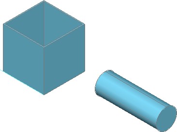
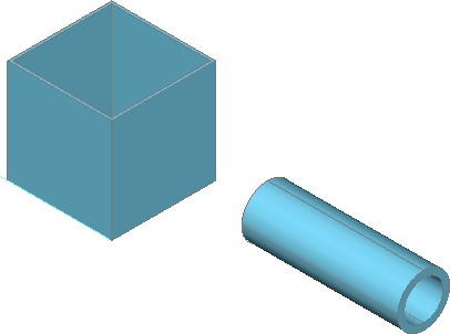
On layer: Solid 3, draw the two solid models using the multiview drawing as a reference. Start the bottom left corner of the cube at 0,0,0. (Figure Step 3A and 3B)
Dimensioned Multiview Drawing
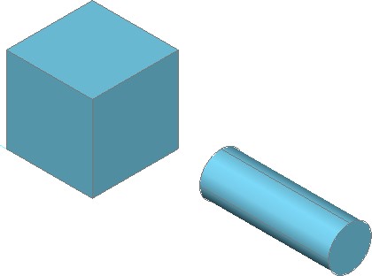
Complete Solid Models
Step 4
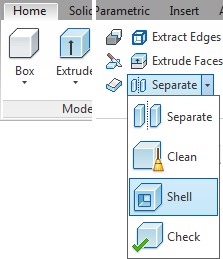
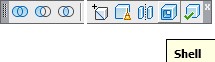
If you are using toolbars, enable the display of the Solids Editing toolbar. If you are using ribbons, enable the Home Tab. (Figure Step 4A and 4B)

Step 5
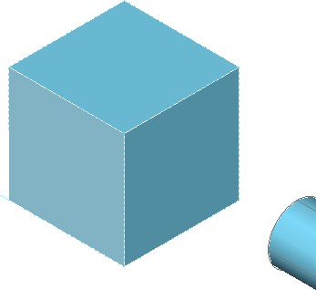
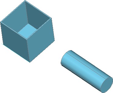
Click the Shell option and enter the command shown below. Enter the wall thickness 0.1 inches. Remove the top face only. (Figure Step 5A, 5B, 5C, and 5D)
Command: SOLIDEDIT
Solids editing automatic checking: SOLIDCHECK=1
Enter a solids editing option [Face/Edge/Body/Undo/eXit] <eXit>:B
Enter a body editing option
[Imprint/seParate solids/Shell/cLean/Check/Undo/eXit] <eXit>: S
Select a 3D solid:
(Select the box.)
Remove faces or [Undo/Add/ALL]: 2 faces found, 2 removed.
(Select the to of the box.)
Remove faces or [Undo/Add/ALL]: A
Select faces or [Undo/Remove/ALL]: 1 faces found.
(Select the side below the top.)
Select faces or [Undo/Remove/ALL]:
Enter the shell offset distance: 0.1
Solid validation started.
Solid validation completed.
Enter a body editing option
Command:
Step 6
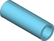
Using what you just learned, click the Shell option again but this time, create a pipe with a 0.25 inch wall thickness. You will have to remove both ends of the pipe. See the command below. (Figure Step 6A, 6B, and 6C)
Command: SOLIDEDIT
Solids editing automatic checking: SOLIDCHECK=1
Enter a solids editing option [Face/Edge/Body/Undo/eXit] <eXit>: B
Enter a body editing option
[Imprint/seParate solids/Shell/cLean/Check/Undo/eXit] <eXit>: S
Select a 3D solid:
Remove faces or [Undo/Add/ALL]: 2 faces found, 2 removed.
Remove faces or [Undo/Add/ALL]: A
Select faces or [Undo/Remove/ALL]: 1 face found.
Select faces or [Undo/Remove/ALL]: R
Remove faces or [Undo/Add/ALL]: 2 faces found, 2 removed.
Remove faces or [Undo/Add/ALL]: A
Select faces or [Undo/Remove/ALL]: 1 face found.
Select faces or [Undo/Remove/ALL]:
Enter the shell offset distance: 0.25
Solid validation started.
Solid validation completed.
Enter a body editing option.
Command:
Step 7
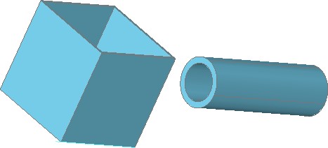
Orbit the model to check for completeness. Set the current view to SE Isometric. (Figure Step 7)
Step 8
Save and close the drawing.
Key Principles
Key Principles in Module 29
- A shell is preformed when material is removed from the interior of a solid model leaving a hollow cavity with a specify wall This is done using the Shell option in the SOLIDEDIT command.
- The Shell option is one of the trickiest options to The problem most student have is not knowing how to remove and add the faces back in.
Lab Exercise 29-1
Time allowed: 30 minutes.
| Drawing Name | Template | Units |
|---|---|---|
| AutoCAD 3D Lab 29-1 | N/A | Millimeters |
Step 1
Open drawing: AutoCAD 3D Lab 24-1. Save and name the drawing with the name: AutoCAD 3D Lab 29-1. (Figure Step 1)
Step 2
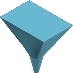
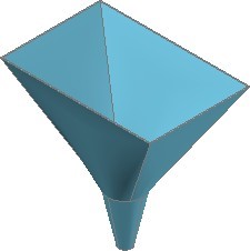
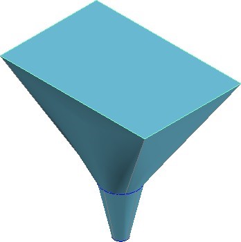
Shell the solid model with a wall thickness of 1.0 mm. Remove the top and bottom to create a funnel. (Figure Step 2A and 2B)
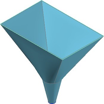
SE Isometric View
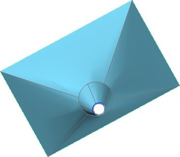
Orbited View
Lab Exercise 29-2
Time allowed: 30 minutes.
| Drawing Name | Template | Units |
|---|---|---|
| AutoCAD 3D Lab 29-2 | N/A | Inches |
Step 1
Open drawing: AutoCAD 3D Lab 24-2. Save and name the drawing with the name: AutoCAD 3D Lab 29-2. (Figure Step 1)
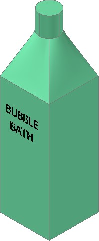
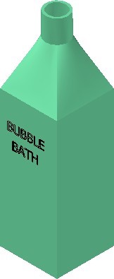
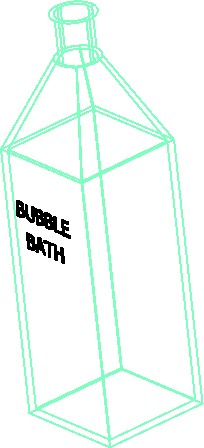
Step 2
Shell the solid model with a wall thickness of 0.1 inches. Remove the top to create a bottle. (Figure Step 2A and 2B)
Lab Exercise 29-3
Time allowed: 60 minutes.
| Drawing Name | Template | Units |
|---|---|---|
| AutoCAD 3D Lab 29-3 | 3D Layout English | Inches |
Step 1
Start a new drawing using the template shown above. Save and name it: AutoCAD 3D Lab 29-3.
Step 2
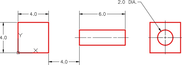
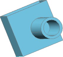
On layer: Solid Wall Plate, draw the solid model shown in the figures. (Figure Step 2A, 2B, and 2C)
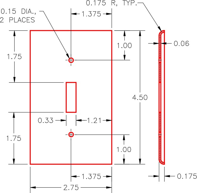
Dimensioned Multiview Drawing
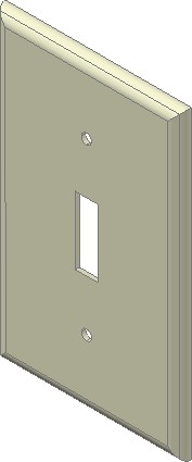
SE Isometric View
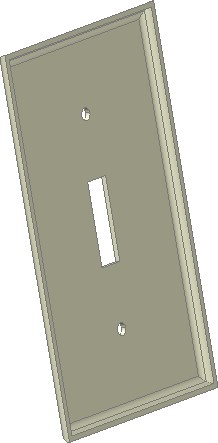
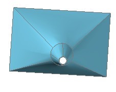
Rotated Back View