
4.5: Module 21 Competency Test No. 4 Open Book
- Page ID
- 19886

\( \newcommand{\vecs}[1]{\overset { \scriptstyle \rightharpoonup} {\mathbf{#1}} } \)
\( \newcommand{\vecd}[1]{\overset{-\!-\!\rightharpoonup}{\vphantom{a}\smash {#1}}} \)
\( \newcommand{\dsum}{\displaystyle\sum\limits} \)
\( \newcommand{\dint}{\displaystyle\int\limits} \)
\( \newcommand{\dlim}{\displaystyle\lim\limits} \)
\( \newcommand{\id}{\mathrm{id}}\) \( \newcommand{\Span}{\mathrm{span}}\)
( \newcommand{\kernel}{\mathrm{null}\,}\) \( \newcommand{\range}{\mathrm{range}\,}\)
\( \newcommand{\RealPart}{\mathrm{Re}}\) \( \newcommand{\ImaginaryPart}{\mathrm{Im}}\)
\( \newcommand{\Argument}{\mathrm{Arg}}\) \( \newcommand{\norm}[1]{\| #1 \|}\)
\( \newcommand{\inner}[2]{\langle #1, #2 \rangle}\)
\( \newcommand{\Span}{\mathrm{span}}\)
\( \newcommand{\id}{\mathrm{id}}\)
\( \newcommand{\Span}{\mathrm{span}}\)
\( \newcommand{\kernel}{\mathrm{null}\,}\)
\( \newcommand{\range}{\mathrm{range}\,}\)
\( \newcommand{\RealPart}{\mathrm{Re}}\)
\( \newcommand{\ImaginaryPart}{\mathrm{Im}}\)
\( \newcommand{\Argument}{\mathrm{Arg}}\)
\( \newcommand{\norm}[1]{\| #1 \|}\)
\( \newcommand{\inner}[2]{\langle #1, #2 \rangle}\)
\( \newcommand{\Span}{\mathrm{span}}\) \( \newcommand{\AA}{\unicode[.8,0]{x212B}}\)
\( \newcommand{\vectorA}[1]{\vec{#1}} % arrow\)
\( \newcommand{\vectorAt}[1]{\vec{\text{#1}}} % arrow\)
\( \newcommand{\vectorB}[1]{\overset { \scriptstyle \rightharpoonup} {\mathbf{#1}} } \)
\( \newcommand{\vectorC}[1]{\textbf{#1}} \)
\( \newcommand{\vectorD}[1]{\overrightarrow{#1}} \)
\( \newcommand{\vectorDt}[1]{\overrightarrow{\text{#1}}} \)
\( \newcommand{\vectE}[1]{\overset{-\!-\!\rightharpoonup}{\vphantom{a}\smash{\mathbf {#1}}}} \)
\( \newcommand{\vecs}[1]{\overset { \scriptstyle \rightharpoonup} {\mathbf{#1}} } \)
\(\newcommand{\longvect}{\overrightarrow}\)
\( \newcommand{\vecd}[1]{\overset{-\!-\!\rightharpoonup}{\vphantom{a}\smash {#1}}} \)
\(\newcommand{\avec}{\mathbf a}\) \(\newcommand{\bvec}{\mathbf b}\) \(\newcommand{\cvec}{\mathbf c}\) \(\newcommand{\dvec}{\mathbf d}\) \(\newcommand{\dtil}{\widetilde{\mathbf d}}\) \(\newcommand{\evec}{\mathbf e}\) \(\newcommand{\fvec}{\mathbf f}\) \(\newcommand{\nvec}{\mathbf n}\) \(\newcommand{\pvec}{\mathbf p}\) \(\newcommand{\qvec}{\mathbf q}\) \(\newcommand{\svec}{\mathbf s}\) \(\newcommand{\tvec}{\mathbf t}\) \(\newcommand{\uvec}{\mathbf u}\) \(\newcommand{\vvec}{\mathbf v}\) \(\newcommand{\wvec}{\mathbf w}\) \(\newcommand{\xvec}{\mathbf x}\) \(\newcommand{\yvec}{\mathbf y}\) \(\newcommand{\zvec}{\mathbf z}\) \(\newcommand{\rvec}{\mathbf r}\) \(\newcommand{\mvec}{\mathbf m}\) \(\newcommand{\zerovec}{\mathbf 0}\) \(\newcommand{\onevec}{\mathbf 1}\) \(\newcommand{\real}{\mathbb R}\) \(\newcommand{\twovec}[2]{\left[\begin{array}{r}#1 \\ #2 \end{array}\right]}\) \(\newcommand{\ctwovec}[2]{\left[\begin{array}{c}#1 \\ #2 \end{array}\right]}\) \(\newcommand{\threevec}[3]{\left[\begin{array}{r}#1 \\ #2 \\ #3 \end{array}\right]}\) \(\newcommand{\cthreevec}[3]{\left[\begin{array}{c}#1 \\ #2 \\ #3 \end{array}\right]}\) \(\newcommand{\fourvec}[4]{\left[\begin{array}{r}#1 \\ #2 \\ #3 \\ #4 \end{array}\right]}\) \(\newcommand{\cfourvec}[4]{\left[\begin{array}{c}#1 \\ #2 \\ #3 \\ #4 \end{array}\right]}\) \(\newcommand{\fivevec}[5]{\left[\begin{array}{r}#1 \\ #2 \\ #3 \\ #4 \\ #5 \\ \end{array}\right]}\) \(\newcommand{\cfivevec}[5]{\left[\begin{array}{c}#1 \\ #2 \\ #3 \\ #4 \\ #5 \\ \end{array}\right]}\) \(\newcommand{\mattwo}[4]{\left[\begin{array}{rr}#1 \amp #2 \\ #3 \amp #4 \\ \end{array}\right]}\) \(\newcommand{\laspan}[1]{\text{Span}\{#1\}}\) \(\newcommand{\bcal}{\cal B}\) \(\newcommand{\ccal}{\cal C}\) \(\newcommand{\scal}{\cal S}\) \(\newcommand{\wcal}{\cal W}\) \(\newcommand{\ecal}{\cal E}\) \(\newcommand{\coords}[2]{\left\{#1\right\}_{#2}}\) \(\newcommand{\gray}[1]{\color{gray}{#1}}\) \(\newcommand{\lgray}[1]{\color{lightgray}{#1}}\) \(\newcommand{\rank}{\operatorname{rank}}\) \(\newcommand{\row}{\text{Row}}\) \(\newcommand{\col}{\text{Col}}\) \(\renewcommand{\row}{\text{Row}}\) \(\newcommand{\nul}{\text{Nul}}\) \(\newcommand{\var}{\text{Var}}\) \(\newcommand{\corr}{\text{corr}}\) \(\newcommand{\len}[1]{\left|#1\right|}\) \(\newcommand{\bbar}{\overline{\bvec}}\) \(\newcommand{\bhat}{\widehat{\bvec}}\) \(\newcommand{\bperp}{\bvec^\perp}\) \(\newcommand{\xhat}{\widehat{\xvec}}\) \(\newcommand{\vhat}{\widehat{\vvec}}\) \(\newcommand{\uhat}{\widehat{\uvec}}\) \(\newcommand{\what}{\widehat{\wvec}}\) \(\newcommand{\Sighat}{\widehat{\Sigma}}\) \(\newcommand{\lt}{<}\) \(\newcommand{\gt}{>}\) \(\newcommand{\amp}{&}\) \(\definecolor{fillinmathshade}{gray}{0.9}\)21
Module 21 Competency Test No. 4 Open Book
Wally Baumback
Learning Outcomes
When you have completed this module, you will be able to:
- Within a two hour time limit, complete a written exam and a lab exercise.
The Inventor book was written with competency based modules. What that means is that you have not completed each module until you have mastered it. The Competency Test module contains multiple choice questions and a comprehensive lab exercise to test your mastery of the set of modules that you completed. There are no answers or keys supplied in a Competency Test module since it is meant to be checked by your instructor. If there are any parts of this module that you have trouble completing, you should go back and reread the module or modules containing the information that you are having trouble with. If necessary, redo as many lab exercises required until you fully understand the material.
If you are Completing this book:
- Without the aid of an instructor, complete the written test and the lab exercise.
- In a classroom with an instructor, the instructor will give instructions on what to do after you have completed this module.
Multiple Choice Questions
Select the BEST answer.
- When you are selecting objects with a window, which window selects all the objects that are totally inside it and the ones that it crosses?
- Square Window
- Crossing Window
- Extruded Window
- Rectangular Window
- Polygon Window
- What is the name for two or more objects that are connected at their endpoints and then treated as one object in the OFFSET command?
- Loop
- Continuous
- Area
- Polyloop
- Window
- What are the basic sketching planes (XY, XZ, YZ), the three axis (X, Y, Z) and the Center Point called?
- Work Planes
- Work Points
- Work Features
- Work Sketches
- Work Axis
- What is the maximum number of sides that the POLYGON command can draw a regular polygon?
- 20
- 100
- 120
- 180
- 256
- When the graphic cursor appears as a ruler, what units are you measuring in? Select the BEST answer.
- English Units
- Document Units
- System Units
- Metric Units
- Actual Units
- What command is used to extend the length of an existing line or an arc?
- LENGTHEN
- EXTEND
- LINE
- LENGTH
- STRETCH
- What does an aligned dimension measure?
- The delta X or delta Y distance between two points.
- The diameter of circle or radius of an arc.
- The true length of a line or the true distance between two points.
- The horizontal or vertical distance between two points.
- The angle between two lines or the angle between the imaginary lines between three points.
- What best describes the threads created using the THREAD command?
- Graphical representations of the actual thread.
- A texture
- The actual thread.
- They are enlarged to look better.
- Center
- What is a parametric construction plane inserted on the model or in model space called?
- A Work Plane
- A Work Point
- A Work Feature
- A Work Sketch
- A Work Model
- What is an angular dimension measuring?
- The delta X or delta Y distance between two points.
- The diameter of circle or radius of an arc.
- The true length of a line or the true distance between two points.
- The horizontal or vertical distance between two points.
- The angle between two lines or the angle between the imaginary lines between three points.
Lab Exercise 21-1
Time allowed: 2 hours.
| Part Name | Project | Units | Template | Color | Material |
| Inventor Lab 21-1 | Inventor Course | Millimeters | Metric-Modules Part (mm).ipt | Machined-Aluminum | Aluminum-6061 |
Step 1
Project the Center Point onto the Base plane.
Step 2
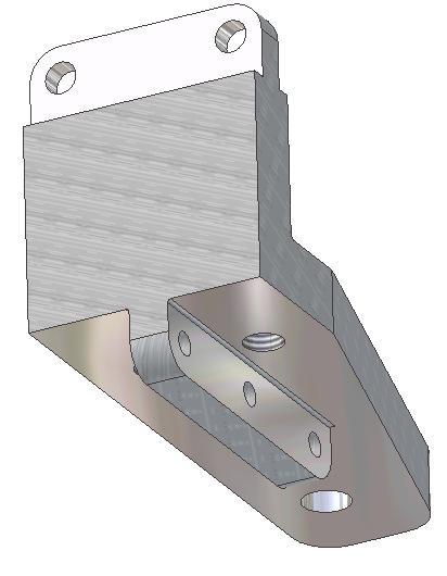
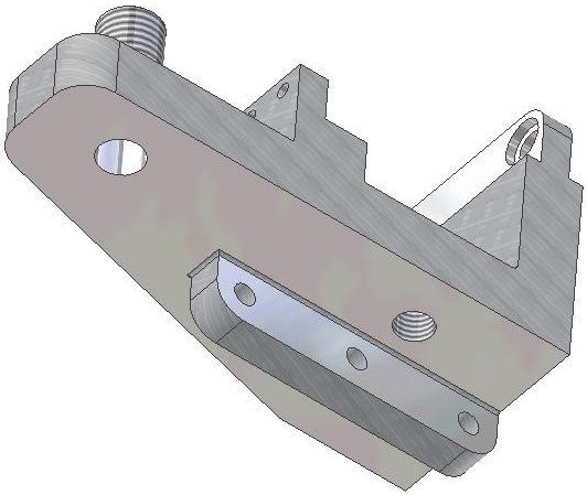
Note the location of X0Y0Z0. Draw the necessary sketches and extrude them to produce the solid model shown below. Apply all of the necessary geometrical and dimensional constraints to maintain the objects shape and size. All sketches must be fully constrained. (Figure Step 2A and 2B)
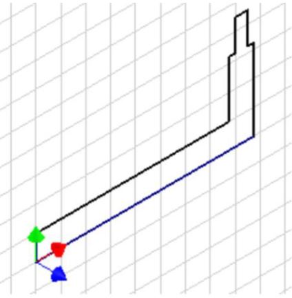
Suggested Base Sketch –
Right Side (YZ) Plane
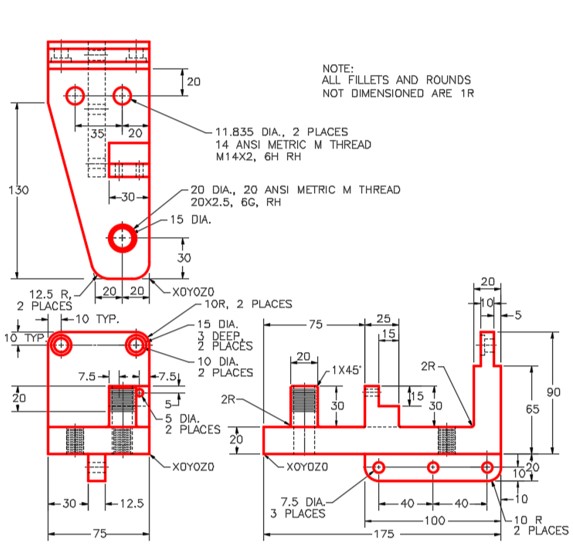
Dimensioned Multiview Drawing
Competency [Click to see image full size]
Step 3
Create the fillets and chamfers after the model is totally constructed.
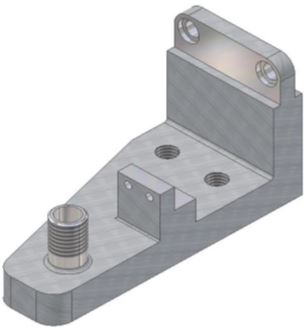
Step 4
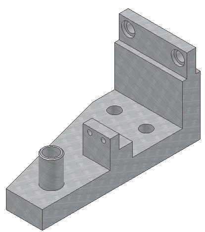
Apply the colour shown above. (Figure Step 4)
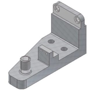
Solid Model
Home View
Step 5
Move the End of Part Icon up above the fillets as shown in the figure. Suppress all of the threaded features. (Figure Step 5)
Step 6
Find the following to a precision of 6 decimal points: (Figure Step 6)
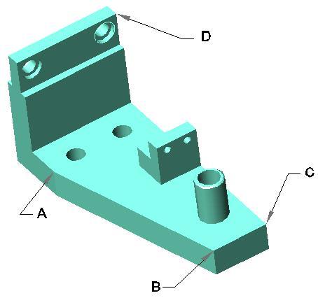
A The XYZ coordinates of corner D.
____________________________
B The length of the edge from corner A to corner B.
____________________________
C The distance from corner A to corner C.
____________________________
D The distance from corner C to corner D.
____________________________
E The angle between the edges B to C and B
____________________________
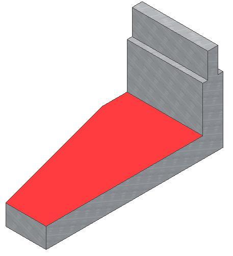
Step 8
The area of the shaded area of Figure Step 8. Do NOT include the area of features on the plane.
____________________________
Step 9
The perimeter of the shaded plane in Figure Step 9.
____________________________
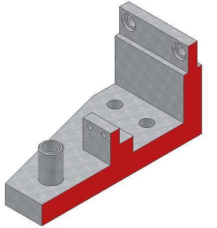
Step 10
The area of the shaded area of Figure Step 10. The area should include the complete surface without any features.
____________________________
Step 11
Using the three figures below, change the colors of the faces shown to: Aluminum – Polished. (Figure Step 11A, 11B, and 11C)
Step 12
- If you are a student completing this course in a classroom setting, your instructor will give you instructions on what to do after you complete this module.
- If you are an online student doing this course by correspondence, send an email to your instructor with the answers from the measurement questions in this module. For example:
| 7A | The XYZ coordinates of corner D is ___________ . |
| 7B | The length of the edge from corner A to corner B is ___________ . |
| 7C | The distance from corner A to corner C is ___________ . |
| 7D | The distance from corner C to corner D is ___________ . |
| 7E | The angle between the edges B to C and B to A is ___________ . |
| 8 | The area of the shaded area of Figure Step 8 is ___________ . |
| 9 | The perimeter of the shaded plane in Figure Step 9 is ___________ . |
| 10 | The area of the shaded area of Figure Step 10 is ___________ . |
| 12A | The mass of the solid model in grams is ___________ . |
| 12B | The mass of the solid model in pounds is ___________ . |
The answers in the email can be given as follows:
| 7A | ___________ . |
| 7B | ___________ . |
| 7C | ___________ . |
| 7D | ___________ . |
| 7E | ___________ . |
| 8 | ___________ . |
| 9 | ___________ . |
| 10 | ___________ . |
| 12A | ___________ . |
| 12B | ___________ . |